EP0182075A2 - Verfahren zur Ortssicherung - Google Patents
Verfahren zur Ortssicherung Download PDFInfo
- Publication number
- EP0182075A2 EP0182075A2 EP85112856A EP85112856A EP0182075A2 EP 0182075 A2 EP0182075 A2 EP 0182075A2 EP 85112856 A EP85112856 A EP 85112856A EP 85112856 A EP85112856 A EP 85112856A EP 0182075 A2 EP0182075 A2 EP 0182075A2
- Authority
- EP
- European Patent Office
- Prior art keywords
- measurement
- tip
- pit
- sample
- detector
- Prior art date
- Legal status (The legal status is an assumption and is not a legal conclusion. Google has not performed a legal analysis and makes no representation as to the accuracy of the status listed.)
- Withdrawn
Links
Images
Classifications
-
- G—PHYSICS
- G01—MEASURING; TESTING
- G01N—INVESTIGATING OR ANALYSING MATERIALS BY DETERMINING THEIR CHEMICAL OR PHYSICAL PROPERTIES
- G01N21/00—Investigating or analysing materials by the use of optical means, i.e. using sub-millimetre waves, infrared, visible or ultraviolet light
- G01N21/17—Systems in which incident light is modified in accordance with the properties of the material investigated
- G01N21/25—Colour; Spectral properties, i.e. comparison of effect of material on the light at two or more different wavelengths or wavelength bands
- G01N21/251—Colorimeters; Construction thereof
- G01N21/253—Colorimeters; Construction thereof for batch operation, i.e. multisample apparatus
-
- G—PHYSICS
- G01—MEASURING; TESTING
- G01N—INVESTIGATING OR ANALYSING MATERIALS BY DETERMINING THEIR CHEMICAL OR PHYSICAL PROPERTIES
- G01N21/00—Investigating or analysing materials by the use of optical means, i.e. using sub-millimetre waves, infrared, visible or ultraviolet light
- G01N21/17—Systems in which incident light is modified in accordance with the properties of the material investigated
- G01N21/59—Transmissivity
- G01N21/5907—Densitometers
- G01N2021/598—Features of mounting, adjusting
- G01N2021/5984—Features of mounting, adjusting height adjustable
-
- G—PHYSICS
- G01—MEASURING; TESTING
- G01N—INVESTIGATING OR ANALYSING MATERIALS BY DETERMINING THEIR CHEMICAL OR PHYSICAL PROPERTIES
- G01N2201/00—Features of devices classified in G01N21/00
- G01N2201/04—Batch operation; multisample devices
- G01N2201/0446—Multicell plate, sequential
Definitions
- the invention concerns a method for the measurement of optical density and an apparatus in which a sample disc comprising several sample vessels is displaced underneath the measurement tip so that each sample vessel can be measured. More specifically, the invention concerns a method by means of which the exact location of the sample pit underneath the measurement tip can be secured.
- a so-called microdisc is used as the base for the samples, the samples to be studied being dosed into the pits in the said disc.
- the disc is displaced on the measurement plane of the photometer so that the pit to be measured at each particular time becomes positioned facing the lower tip of the measurement head.
- a microdisc reading device in which the pits in one pit line of the disc are measured at a time.
- the device has a disc displacement mechanism, by means of which the exact location of the disc underneath the measurement tips is secured. Once the disc has adopted its correct location, the measurement tips are lowered into the sample pits so as to perform the measurement.
- a microdisc reading device which has one measurement tip, the pit to be measured being shifted to underneath the said tip.
- the measurement tip has a globular tip, but its diameter is larger than the pit.
- the measurement tip is attached to a resilient arm, which presses the tip against the pit. If the pit is not exactly at the correct location, the disc tends to be shifted by the effect of the force of the arm until the measurement tip and the pit face each other.
- the object of the present invention is to provide a simple arrangement for securing the exact location of the sample disc underneath the measurement tip, in which said arrangement, moreover, performance of the measurement is prevented if the pit to be measured is not exactly in its correct location.
- a further object of the invention is to provide an arrangement which performs the measurement automatically as soon as the pit is exactly in its correct location.
- the sample-disc reading device in accordance with the invention includes a vertically displaceable measurement tip.
- the end of the measurement tip is in such a way narrowed that it can penetrate a certain distance into the sample pit.
- the device is provided with a detector which detects the movement of the measurement tip and which is set so as to prevent performance of measurement unless the measurement tip is in the lower position. In this way, the measurement can be carried out only when the desired pit and the measurement tip are exactly facing each other.
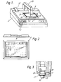
- the pit disc 3 to be measured is introduced onto the measurement plane 2 of the photometer so that the pit 10 to be measured becomes positioned facing the lower tip 6 of the measurement head 5.
- the pit 10 concerned is measured by means of photometric methods.
- the measurement result is indicated to the operator in the display unit 11, produced as an output by means of the printer 12 of the apparatus, or it is transmitted to an auxiliary apparatus, e.g. to an external printer.
- the pit disc 3 can be displaced freely on the measurement plane 2 from pit to pit, i.e. the pits 9 can be measured in any sequence whatsoever.
- the locations of the pits 9 in the disc are coded in the 96-pit pit disc so that the 12 vertical lines are provided with numbers from left to right in the numerical order 1 to 12, and the 8 horizontal lines are denoted with letters from the top downwards in the alphabetical order A to H.
- An indicator structure may consist, e.g., of magnetic rods placed at the edges of the sample frame as well as of inductive approach detectors fitted underneath the measurement plane.
- the magnetic rods pass a signal only to the detector placed straight underneath. In this way, the location of the disc can be identified precisely in each particular case.
- the measurement tip is cylindrical, and at its upper portion there is an annular flange 17.
- the end of the optical system 16 extends to inside the annular flange 17.
- the beam of light coming from a source of light placed below the measurement plane passes through the pit to be measured and through the measurement tip 6 and the optical system 16 further to the detector.
- the measurement tip is placed in a vertical bore provided in the measurement head, in which said bore it may move vertically.
- the opening of the bore is, however, smaller than the flange 17, so that only the end of the measurement tip projects out of the bore.
- the measurement head is provided with a microswitch 7, whose lever 18 is mounted so as to rest against a widening 15 of the flange 17 when the measurement tip is not in the lower position.
- the switch 7 is connected to the measurement system of the apparatus and set so as to prevent measurement when the switch is on.
- the apparatus is provided with an automatic system which performs measurement as the switch is switched off.
- the pit disc to be measured is placed in a measurement frame 4, and the frame is placed on the measurement plane 2.
- the measurement arm 13 is locked so that the measurement tip 6 is in a pit and lowered down so that the detector 7 is not switched on, and thus the measurement can be carried out.
- the measurement tip is pressed into the measurement head, and the widening 15 of the measurement tip acts upon the detector lever 18, whereby the measurement is prevented.
- measurement cannot be performed, e.g., when the measurement tip is between the pits in the pit disc.
- the measurement tip is returned by the effect of a spring 8 into a pit in the pit disc.
- the measurement tip releases the detector and thereby permits measurement of the pit concerned.
- the measurement tip is thicker than the diameter of the sample pit, but its lower tip 14 is narrowed, whereby, in the measurement position, the edge of the sample pit rests against the lower tip.
- the lower tip 14 and the edge of the sample pit are shaped so that, when moving to the side, the edge of the pit readily pushes the measurement tip 6 upwards.
- the height of the measurement arm 13 relative the measurement plane 2 can preferably be adjusted and locked at the desired height, whereby it is possible to use pit discs of different heights in the apparatus.
- optical system and the computer and output devices necessary for the equipment can be prepared, as required, out of components known and available in the field concerned.
- the measurement tip is fitted so as to receive the light coming from the sample.
Landscapes
- Physics & Mathematics (AREA)
- Biochemistry (AREA)
- Health & Medical Sciences (AREA)
- Life Sciences & Earth Sciences (AREA)
- Chemical & Material Sciences (AREA)
- Analytical Chemistry (AREA)
- Spectroscopy & Molecular Physics (AREA)
- General Health & Medical Sciences (AREA)
- General Physics & Mathematics (AREA)
- Immunology (AREA)
- Pathology (AREA)
- Optical Measuring Cells (AREA)
- Investigating Or Analysing Materials By Optical Means (AREA)
Applications Claiming Priority (2)
| Application Number | Priority Date | Filing Date | Title |
|---|---|---|---|
| FI844576 | 1984-11-21 | ||
| FI844576A FI844576A0 (fi) | 1984-11-21 | 1984-11-21 | Foerfarande foer foersaekring av position. |
Publications (2)
| Publication Number | Publication Date |
|---|---|
| EP0182075A2 true EP0182075A2 (de) | 1986-05-28 |
| EP0182075A3 EP0182075A3 (de) | 1987-06-10 |
Family
ID=8519934
Family Applications (1)
| Application Number | Title | Priority Date | Filing Date |
|---|---|---|---|
| EP85112856A Withdrawn EP0182075A3 (de) | 1984-11-21 | 1985-10-10 | Verfahren zur Ortssicherung |
Country Status (3)
| Country | Link |
|---|---|
| EP (1) | EP0182075A3 (de) |
| JP (1) | JPS61129553A (de) |
| FI (1) | FI844576A0 (de) |
Cited By (1)
| Publication number | Priority date | Publication date | Assignee | Title |
|---|---|---|---|---|
| EP0269876A3 (en) * | 1986-11-24 | 1988-07-06 | Abbott Laboratories | Sample focuser for solid-phase analytical device |
Family Cites Families (4)
| Publication number | Priority date | Publication date | Assignee | Title |
|---|---|---|---|---|
| US4115010A (en) * | 1976-02-03 | 1978-09-19 | Merck & Co., Inc. | Automated plate reader |
| EP0030148A1 (de) * | 1979-11-28 | 1981-06-10 | Portalab Instruments Limited | Tragbares Photometer |
| US4299493A (en) * | 1979-12-10 | 1981-11-10 | Harrison Venton R | Auto-optical centering device for photometers |
| US4397560A (en) * | 1981-04-23 | 1983-08-09 | Bio-Tek Instruments, Inc. | Photometer with microtray well position indicator |
-
1984
- 1984-11-21 FI FI844576A patent/FI844576A0/fi not_active Application Discontinuation
-
1985
- 1985-10-10 EP EP85112856A patent/EP0182075A3/de not_active Withdrawn
- 1985-11-21 JP JP26231585A patent/JPS61129553A/ja active Pending
Cited By (1)
| Publication number | Priority date | Publication date | Assignee | Title |
|---|---|---|---|---|
| EP0269876A3 (en) * | 1986-11-24 | 1988-07-06 | Abbott Laboratories | Sample focuser for solid-phase analytical device |
Also Published As
| Publication number | Publication date |
|---|---|
| EP0182075A3 (de) | 1987-06-10 |
| FI844576A0 (fi) | 1984-11-21 |
| JPS61129553A (ja) | 1986-06-17 |
Similar Documents
| Publication | Publication Date | Title |
|---|---|---|
| CA2038912C (en) | Fluid dispensing system with optical locator | |
| KR910005927B1 (ko) | 원자로 연료조립체 검사기 | |
| US5027075A (en) | Apparatus for determination of probe contact with a liquid surface | |
| US5138868A (en) | Calibration method for automated assay instrument | |
| US4692609A (en) | Method and apparatus for indicating and sensing pipetting positions | |
| US5380666A (en) | Method for scanning and centering containers filled with a liquid | |
| US4833382A (en) | Method and apparatus for use in microscope investigations | |
| KR900003748B1 (ko) | 독립선형 크기 측정 장치용 감지장치 | |
| ES2124223T3 (es) | Aparato y procedimiento para analisis de sangre basados en la sedimentacion. | |
| EP0286419A3 (en) | Method and apparatus for analysing liquid properties | |
| US3520609A (en) | Method and apparatus for detecting agglutination reactions | |
| JPH08501884A (ja) | 物体の大きさを測定するための方法および装置 | |
| EP0442112B1 (de) | Verfahren und Vorrichtung zur Photodetektion | |
| JPH02216058A (ja) | テストキャリヤ分析システム | |
| US5073719A (en) | Apparatus for the evaluation of the erythrosedimentation rate and other | |
| CA1088774A (en) | Penetration hardness tester with digital readout | |
| EP0055234B1 (de) | Verfahren zum Zeitmarkieren eines Senkungsprozesses und Vorrichtung zur Durchführung dieses Verfahrens | |
| GB2069974A (en) | Sampling controller | |
| JPS62235570A (ja) | 試料サンプリング装置 | |
| WO1994015181A1 (en) | A method and device for determining the level of gaseous or liqu id media in tubes | |
| JPS61129553A (ja) | サンプルピツトの位置決め方法とその装置 | |
| GB2056702A (en) | Measuring contact lenses | |
| JPS6429730A (en) | Minute material testing instrument | |
| US7793533B2 (en) | Test device for metal detector portal structure | |
| JPH02219000A (ja) | X線装置の自動制御装置 |
Legal Events
| Date | Code | Title | Description |
|---|---|---|---|
| PUAI | Public reference made under article 153(3) epc to a published international application that has entered the european phase |
Free format text: ORIGINAL CODE: 0009012 |
|
| AK | Designated contracting states |
Kind code of ref document: A2 Designated state(s): AT BE CH DE FR GB IT LI LU NL SE |
|
| PUAL | Search report despatched |
Free format text: ORIGINAL CODE: 0009013 |
|
| AK | Designated contracting states |
Kind code of ref document: A3 Designated state(s): AT BE CH DE FR GB IT LI LU NL SE |
|
| STAA | Information on the status of an ep patent application or granted ep patent |
Free format text: STATUS: THE APPLICATION IS DEEMED TO BE WITHDRAWN |
|
| 18D | Application deemed to be withdrawn |
Effective date: 19871211 |
|
| RIN1 | Information on inventor provided before grant (corrected) |
Inventor name: KOVANEN, ILKKA Inventor name: KAINIEMI, AIMO |