EP0182094B1 - Procédé de fabrication d'un emballage muni d'une ouverture pouvant être refermée - Google Patents
Procédé de fabrication d'un emballage muni d'une ouverture pouvant être refermée Download PDFInfo
- Publication number
- EP0182094B1 EP0182094B1 EP85113071A EP85113071A EP0182094B1 EP 0182094 B1 EP0182094 B1 EP 0182094B1 EP 85113071 A EP85113071 A EP 85113071A EP 85113071 A EP85113071 A EP 85113071A EP 0182094 B1 EP0182094 B1 EP 0182094B1
- Authority
- EP
- European Patent Office
- Prior art keywords
- container
- outer container
- inner container
- packaging
- region
- Prior art date
- Legal status (The legal status is an assumption and is not a legal conclusion. Google has not performed a legal analysis and makes no representation as to the accuracy of the status listed.)
- Expired - Lifetime
Links
- 238000000034 method Methods 0.000 title claims abstract description 40
- 238000004806 packaging method and process Methods 0.000 claims abstract description 82
- 239000000463 material Substances 0.000 claims abstract description 59
- 230000008569 process Effects 0.000 claims abstract description 35
- 238000004519 manufacturing process Methods 0.000 claims abstract description 23
- 238000007664 blowing Methods 0.000 claims abstract description 8
- 239000012815 thermoplastic material Substances 0.000 claims abstract description 8
- 230000015572 biosynthetic process Effects 0.000 claims abstract description 7
- 238000001125 extrusion Methods 0.000 claims abstract description 7
- 230000000694 effects Effects 0.000 claims description 7
- 238000009826 distribution Methods 0.000 claims description 5
- 238000007493 shaping process Methods 0.000 claims description 5
- 230000009467 reduction Effects 0.000 claims description 3
- 238000010101 extrusion blow moulding Methods 0.000 claims 1
- 239000010410 layer Substances 0.000 description 13
- 238000000071 blow moulding Methods 0.000 description 5
- 230000009471 action Effects 0.000 description 4
- 238000007654 immersion Methods 0.000 description 4
- 238000006073 displacement reaction Methods 0.000 description 3
- 239000004033 plastic Substances 0.000 description 3
- 229920003023 plastic Polymers 0.000 description 3
- 238000007789 sealing Methods 0.000 description 3
- 239000000443 aerosol Substances 0.000 description 2
- 230000004888 barrier function Effects 0.000 description 2
- 230000008901 benefit Effects 0.000 description 2
- 238000001816 cooling Methods 0.000 description 2
- 239000013013 elastic material Substances 0.000 description 2
- 238000002347 injection Methods 0.000 description 2
- 239000007924 injection Substances 0.000 description 2
- 239000012528 membrane Substances 0.000 description 2
- 238000004064 recycling Methods 0.000 description 2
- 229920001169 thermoplastic Polymers 0.000 description 2
- 239000002699 waste material Substances 0.000 description 2
- 238000003466 welding Methods 0.000 description 2
- 239000004698 Polyethylene Substances 0.000 description 1
- 230000002730 additional effect Effects 0.000 description 1
- 239000002318 adhesion promoter Substances 0.000 description 1
- 239000000853 adhesive Substances 0.000 description 1
- 230000001070 adhesive effect Effects 0.000 description 1
- 239000012790 adhesive layer Substances 0.000 description 1
- 238000004873 anchoring Methods 0.000 description 1
- QVGXLLKOCUKJST-UHFFFAOYSA-N atomic oxygen Chemical compound [O] QVGXLLKOCUKJST-UHFFFAOYSA-N 0.000 description 1
- 239000011324 bead Substances 0.000 description 1
- 230000006835 compression Effects 0.000 description 1
- 238000007906 compression Methods 0.000 description 1
- 239000002537 cosmetic Substances 0.000 description 1
- 238000010586 diagram Methods 0.000 description 1
- 238000009792 diffusion process Methods 0.000 description 1
- 239000003814 drug Substances 0.000 description 1
- 239000010408 film Substances 0.000 description 1
- 230000001788 irregular Effects 0.000 description 1
- 239000007788 liquid Substances 0.000 description 1
- 239000000203 mixture Substances 0.000 description 1
- 229910052760 oxygen Inorganic materials 0.000 description 1
- 239000001301 oxygen Substances 0.000 description 1
- 239000005022 packaging material Substances 0.000 description 1
- 230000000149 penetrating effect Effects 0.000 description 1
- -1 polyethylene Polymers 0.000 description 1
- 229920000573 polyethylene Polymers 0.000 description 1
- 238000012805 post-processing Methods 0.000 description 1
- 238000012545 processing Methods 0.000 description 1
- 239000007921 spray Substances 0.000 description 1
- 230000003068 static effect Effects 0.000 description 1
- 239000000126 substance Substances 0.000 description 1
- 239000004416 thermosoftening plastic Substances 0.000 description 1
- 239000010409 thin film Substances 0.000 description 1
Images



Classifications
-
- B—PERFORMING OPERATIONS; TRANSPORTING
- B65—CONVEYING; PACKING; STORING; HANDLING THIN OR FILAMENTARY MATERIAL
- B65D—CONTAINERS FOR STORAGE OR TRANSPORT OF ARTICLES OR MATERIALS, e.g. BAGS, BARRELS, BOTTLES, BOXES, CANS, CARTONS, CRATES, DRUMS, JARS, TANKS, HOPPERS, FORWARDING CONTAINERS; ACCESSORIES, CLOSURES, OR FITTINGS THEREFOR; PACKAGING ELEMENTS; PACKAGES
- B65D83/00—Containers or packages with special means for dispensing contents
- B65D83/771—Containers or packages with special means for dispensing contents for dispensing fluent contents by means of a flexible bag or a deformable membrane or diaphragm
-
- B—PERFORMING OPERATIONS; TRANSPORTING
- B05—SPRAYING OR ATOMISING IN GENERAL; APPLYING FLUENT MATERIALS TO SURFACES, IN GENERAL
- B05B—SPRAYING APPARATUS; ATOMISING APPARATUS; NOZZLES
- B05B11/00—Single-unit hand-held apparatus in which flow of contents is produced by the muscular force of the operator at the moment of use
- B05B11/01—Single-unit hand-held apparatus in which flow of contents is produced by the muscular force of the operator at the moment of use characterised by the means producing the flow
- B05B11/02—Membranes or pistons acting on the contents inside the container, e.g. follower pistons
- B05B11/026—Membranes separating the content remaining in the container from the atmospheric air to compensate underpressure inside the container
-
- B—PERFORMING OPERATIONS; TRANSPORTING
- B29—WORKING OF PLASTICS; WORKING OF SUBSTANCES IN A PLASTIC STATE IN GENERAL
- B29C—SHAPING OR JOINING OF PLASTICS; SHAPING OF MATERIAL IN A PLASTIC STATE, NOT OTHERWISE PROVIDED FOR; AFTER-TREATMENT OF THE SHAPED PRODUCTS, e.g. REPAIRING
- B29C49/00—Blow-moulding, i.e. blowing a preform or parison to a desired shape within a mould; Apparatus therefor
- B29C49/02—Combined blow-moulding and manufacture of the preform or the parison
- B29C49/04—Extrusion blow-moulding
-
- B—PERFORMING OPERATIONS; TRANSPORTING
- B29—WORKING OF PLASTICS; WORKING OF SUBSTANCES IN A PLASTIC STATE IN GENERAL
- B29C—SHAPING OR JOINING OF PLASTICS; SHAPING OF MATERIAL IN A PLASTIC STATE, NOT OTHERWISE PROVIDED FOR; AFTER-TREATMENT OF THE SHAPED PRODUCTS, e.g. REPAIRING
- B29C49/00—Blow-moulding, i.e. blowing a preform or parison to a desired shape within a mould; Apparatus therefor
- B29C49/22—Blow-moulding, i.e. blowing a preform or parison to a desired shape within a mould; Apparatus therefor using multilayered preforms or parisons
-
- B—PERFORMING OPERATIONS; TRANSPORTING
- B29—WORKING OF PLASTICS; WORKING OF SUBSTANCES IN A PLASTIC STATE IN GENERAL
- B29C—SHAPING OR JOINING OF PLASTICS; SHAPING OF MATERIAL IN A PLASTIC STATE, NOT OTHERWISE PROVIDED FOR; AFTER-TREATMENT OF THE SHAPED PRODUCTS, e.g. REPAIRING
- B29C2793/00—Shaping techniques involving a cutting or machining operation
- B29C2793/0054—Shaping techniques involving a cutting or machining operation partially cutting through the material
-
- B—PERFORMING OPERATIONS; TRANSPORTING
- B29—WORKING OF PLASTICS; WORKING OF SUBSTANCES IN A PLASTIC STATE IN GENERAL
- B29C—SHAPING OR JOINING OF PLASTICS; SHAPING OF MATERIAL IN A PLASTIC STATE, NOT OTHERWISE PROVIDED FOR; AFTER-TREATMENT OF THE SHAPED PRODUCTS, e.g. REPAIRING
- B29C2949/00—Indexing scheme relating to blow-moulding
- B29C2949/30—Preforms or parisons made of several components
- B29C2949/3086—Interaction between two or more components, e.g. type of or lack of bonding
- B29C2949/3094—Interaction between two or more components, e.g. type of or lack of bonding preform having at least partially loose components, e.g. at least partially loose layers
-
- B—PERFORMING OPERATIONS; TRANSPORTING
- B29—WORKING OF PLASTICS; WORKING OF SUBSTANCES IN A PLASTIC STATE IN GENERAL
- B29K—INDEXING SCHEME ASSOCIATED WITH SUBCLASSES B29B, B29C OR B29D, RELATING TO MOULDING MATERIALS OR TO MATERIALS FOR MOULDS, REINFORCEMENTS, FILLERS OR PREFORMED PARTS, e.g. INSERTS
- B29K2995/00—Properties of moulding materials, reinforcements, fillers, preformed parts or moulds
- B29K2995/0037—Other properties
- B29K2995/0046—Elastic
-
- B—PERFORMING OPERATIONS; TRANSPORTING
- B29—WORKING OF PLASTICS; WORKING OF SUBSTANCES IN A PLASTIC STATE IN GENERAL
- B29L—INDEXING SCHEME ASSOCIATED WITH SUBCLASS B29C, RELATING TO PARTICULAR ARTICLES
- B29L2009/00—Layered products
- B29L2009/001—Layered products the layers being loose
-
- B—PERFORMING OPERATIONS; TRANSPORTING
- B29—WORKING OF PLASTICS; WORKING OF SUBSTANCES IN A PLASTIC STATE IN GENERAL
- B29L—INDEXING SCHEME ASSOCIATED WITH SUBCLASS B29C, RELATING TO PARTICULAR ARTICLES
- B29L2031/00—Other particular articles
- B29L2031/712—Containers; Packaging elements or accessories, Packages
- B29L2031/7158—Bottles
-
- B—PERFORMING OPERATIONS; TRANSPORTING
- B65—CONVEYING; PACKING; STORING; HANDLING THIN OR FILAMENTARY MATERIAL
- B65D—CONTAINERS FOR STORAGE OR TRANSPORT OF ARTICLES OR MATERIALS, e.g. BAGS, BARRELS, BOTTLES, BOXES, CANS, CARTONS, CRATES, DRUMS, JARS, TANKS, HOPPERS, FORWARDING CONTAINERS; ACCESSORIES, CLOSURES, OR FITTINGS THEREFOR; PACKAGING ELEMENTS; PACKAGES
- B65D2231/00—Means for facilitating the complete expelling of the contents
- B65D2231/001—Means for facilitating the complete expelling of the contents the container being a bag
- B65D2231/004—Means for facilitating the complete expelling of the contents the container being a bag comprising rods or tubes provided with radial openings, ribs or the like, e.g. dip-tubes, spiral rods
Definitions
- the invention relates to a method for producing a packaging provided with a closable opening, which is provided with a substantially dimensionally stable outer container, within which a container-flexible material accommodating the filling material is arranged, wherein in the coextrusion process, first of all, a preform consisting of two essentially coaxial tubular sections is extruded and the simultaneously extruded sections are made of different thermoplastic materials that do not come into contact with one another and, after reaching the required length, are expanded in a blow mold using internal positive pressure until the outer section touches the wall of the blow mold and the bottom of the packaging underneath Squeezing excess material while forming a weld seam is formed on the inner container.
- Packages are known which are designed such that the outer container is formed by a cardboard box within which the inner container is arranged.
- the static pressure of the contents can be used to empty the inner bag. This assumes that the emptying opening is in the lower area of the packaging.
- Packaging for filling goods is also known which is released from the packaging in the form of an aerosol.
- the actual filling material is located inside a bag, which is arranged inside a generally metallic outer container. There is a pressure medium in the area between the bag and the metallic container, under the influence of which the bag is compressed and thus emptied.
- This packaging and also such as e.g. DE-A-2,915,228, 3,045,710 and 3,240,300 describe a manufacturing method which is characterized in that the outer container and the inner container are produced separately from one another and then joined together. It is not possible to produce such packaging in one operation. As a result, small-volume packaging, such as those used for aerosol, are relatively expensive.
- US-A-3,940,001 a container made of thermoplastic material is known, which consists of several layers, one of which gives the body the required rigidity and impact resistance, whereas another layer, which is made of another material, acts, for example, as a diffusion barrier .
- the teaching of this document is based on the consideration that such containers, for example those produced in the coextrusion blow molding process, are hardly recyclable, since the different materials used for their production are present as a mixture when recycled for recycling, which as such cannot be processed. For this reason, the teaching according to US-A-3,940,001 is based on the object of designing such a container in such a way that the individual types of material forming it can be obtained separately from one another for recycling.
- the outer layer which brings about the mechanical strength and inherent rigidity of the packaging, consists of a brittle, non-elastic material
- the inner layer consists of an elastic material.
- the used containers are to be subjected to mechanical stress, for example in a comminution device, with the result that the outer, brittle layer is broken up, that is to say broken down into smaller individual parts, and thereby detaches from the inner layer, which is due to the elasticity of the plastic from which it consists essentially maintains its connection.
- the prerequisite should be that there is little or no adhesion between the layers of the laminated container.
- the teaching conveyed by this publication is therefore not intended to make the packaging suitable for any packaging purpose or to produce it in a particularly economical manner. Rather, the objective of the teaching conveyed by the publication is aimed exclusively at the processing of the container after its use.
- the publication contains no indication that the inner layer represents the actual container, which stands out from the outer layer in the course of emptying, that is to say when the container is used.
- US-A-4,008,830 discloses a package which consists of a substantially dimensionally stable outer container and a flexible inner container which receives the filling material and is emptied by means of a pressure drop generated by a pump.
- the bottom of the outer container is provided with an opening through which the pressure of the surrounding atmosphere permanently acts on the inner container.
- Two possibilities are disclosed with regard to the production of such a packaging.
- the outer container and the inner container are manufactured separately from one another and connected to one another by a cover part, which also contains the pump, using a clamp fit. This type of production is extremely complicated and expensive.
- This also applies to the second production method disclosed in the publication, in which the outer container and the inner container are produced in one piece in a common operation. How this should be done in detail remains undisclosed in the publication. However, several operations are also required here, with the additional problem that the part of the molded body forming the outer container must have a substantially greater wall thickness than the part from which the inner container is formed.
- US-A-3,118,572 also discloses a thermoplastic packaging which has an outer container and a deformable inner container which holds the filling material.
- this packaging is designed as a squeeze bottle with the result that the opening arranged in the outer container is provided with a one-way valve for establishing a connection to the surrounding atmosphere, through which air can only flow from the outside into the space between the inner container and the outer container.
- This known packaging has a complicated structure, so that it is expensive to manufacture.
- the inner container is closed at its end facing away from the discharge opening in that it is connected to the bottom of the outer container.
- this has the disadvantage that the inner container cannot be completely emptied, since it remains connected to the outer container at the bottom thereof.
- the inner container is closed at its end facing away from the discharge opening by a special membrane, so that the connection to the outer container is not necessary.
- the attachment of the membrane is an additional complication and cost of the packaging, which is anyway so complex due to the separate manufacture of the outer container and inner container and the one-way valve that it can hardly be used in practice, since packaging is a mass-produced item, its cheap manufacture The prerequisite for their use is.
- the invention has for its object to modify the method of the type described in the introduction so that it enables the production of packaging, in which the inner container can be separated from the outer container in order to dispense the filling material contained in the packaging, in order to remove the filling material under the action of a pressure drop to let out the inner container.
- the manufacture of such packaging should be simple, so that even small-volume containers can be manufactured inexpensively.
- the packaging should be able to meet certain minimum requirements with regard to manageability and appearance. B. in pharmaceuticals and cosmetics.
- the production of such a packaging is to be simplified in that it can be produced in one operation, apart from certain insignificant post-processing operations, for example removal of waste parts or the like.
- the packaging should also be suitable for highly viscous liquid goods with the possibility of dispensing the latter in doses.
- the invention proposes that the squeezing of excess material takes place without simultaneous formation of a weld seam causing the outer container to close, so that there is a sufficiently large opening in the outer container through which the region between the outer container and the easily deformable bag-like inner container is connected to the ambient atmosphere in order to allow the pressure of the surrounding atmosphere to act permanently on the inner container.
- the outer container of the finished packaging is formed, which conveys the required mechanical rigidity, stability and general manageability to the packaging and also, if necessary, has the surface properties required for decorative purposes, whereas that from the im inner portion of the preform formed bag represents the actual container for the contents. Due to the fact that the materials forming the two containers cannot be welded to one another, the inner, bag-like container, which essentially has the shape of the outer container, will detach itself from the outer container under the action of a pressure gradient when the pressure in the inner container is lower than the one in the outer container.
- a major advantage of the invention is that using the coextrusion blow molding process, it is also possible to produce relatively complicated and irregular packaging in one operation, even with regard to its shape. This makes the manufacturing process neither more complex nor more complicated. Since the inner container can be emptied without air and thus oxygen penetrating from the outside into the inner container, the shelf life of certain contents can be significantly extended, even if the packaging has been opened.
- the opening that connects the area between the outer container and the inner container with the ambient atmosphere can be produced in a simple manner in that, after the shaping process has been completed and the material forming the outer container has sufficiently solidified, a force is exerted on the bottom of the latter, a distance between brings about the opposite wall parts of the bottom of the outer container in the squeezing area. This can be achieved by exerting the force on the bottom of the outer container while the packaging is inside the blow mold, e.g. B.
- the inner section of the preform for producing the inner container can be produced by coextrusion of several layers made of different materials, which are welded to form a unit.
- This method is known per se and is used in particular when it is important to provide the container wall with a barrier layer which prevents certain substances from diffusing through.
- the inner section of the preform would itself consist of at least two, generally three subsections, which, however, are joined by welding at the latest when expanded in the blow mold by welding to form a multilayer unit, with an adhesion promoter layer consisting of a third being consistently between two layers made of different materials Material is arranged, which forms an intensive adhesive bond with the other two materials.
- Such an adhesive layer is missing in the method and in the packaging according to the invention between the outer container and the bag-like inner container.
- the inner container must be movable relative to the outer container under the influence of the pressure gradient already mentioned for the purpose of dispensing filling material, it will generally be expedient to connect the outer container and inner container to one another in the vicinity of the outlet opening of the packaging.
- the need for such a connection also depends on the shape of the packaging.
- the inner container if necessary, advantageously being fastened to the outer container in the region of the bottle neck.
- a certain positive connection between the outer container and the inner container is in any case brought about in one direction by the presence of the bottle shoulder.
- the bottle neck generally has a much smaller diameter than the actual body of the bottle, which fact also favors a fixation of the inner container in the outer container.
- Another possibility is to choose the outer diameter of the tubular preform larger than the outer diameter of the associated area of the blow mold, at least in a partial area of the neck to be produced on the packaging, and, when the latter is closed, excess material from both sections while simultaneously forming at least one weld seam on the inner Squeeze the section without creating a weld on the outer tube at the same time.
- This is a process which corresponds to the formation of the weld seam on the bottom of the inner container with simultaneous squeezing of excess material, the two opposing bottom regions of the outer container remaining unsealed.
- the bottle neck consists of two sections, the parting plane of which runs radially and parallel to its longitudinal axis, with corresponding edge regions of the inner container being clamped between the two sections.
- the neck is provided on the outside with a part that functions as a bandage.
- This can advantageously be a part that can be screwed onto the outside of the bottle neck, e.g. a pump provided with a valve, by manual actuation of which the vacuum required for emptying the inner container can be generated in the former.
- the end region of the inner tubular preform when the packaging is shaped, can be bent outwards over the end boundary of the outer container, so that on the finished packaging this end region covers the end boundary of the outer container.
- a positive connection between the outer container and the inner container is achieved, which, regardless of whether a bottle neck is present, can also be achieved in this way with other container shapes, thereby preventing the inner container from slipping into the outer container.
- the bottle shoulder already mentioned causes a positive connection that is effective in the opposite direction.
- the end region of the inner container which is bent over the end boundary of the outer container, also acts as Can serve sealing ring, which, due to its elastic resilience, facilitates tight fitting of the closure of the packaging or of the pump already mentioned without additional measures.
- the plastic of the outer container is relatively hard due to the function intended for the latter, that is, it does not have the optimal properties for a sealing function with regard to its elastic deformability.
- the inner container which in the rest of the case will normally always be much thinner than the outer container, consists of a material that is also easier to deform elastically, so that it has better properties for a seal than the outer container.
- the invention also relates to a packaging provided with a closable opening, produced in the coextrusion blow molding process, which is provided with a substantially dimensionally stable outer container, within which an inner container holding the filling material is arranged, the outer container and inner container being made of different thermoplastic plastics which are made from one another no connection, and the inner container is made of flexible material and is sealed at its bottom end by a weld.
- This packaging is characterized in that the outer container has at least one opening through which the area between the outer container and the bag-like inner container can be connected to the ambient atmosphere, the outer container having at its bottom end two mutually opposite wall regions which delimit the opening such that the Pressure of the surrounding atmosphere acts permanently on the inner container.
- the invention further provides the possibility that by appropriate distribution of the wall thickness of the inner container this is compressed in a controlled manner during the emptying process under the influence of the pressure drop, so that the displacement of the filling material thereby caused can take place in a targeted manner, e.g. B. in such a way that the reduction in cross section at one end region of the inner container continues during emptying towards the other end, it being immaterial whether the emptying takes place in one operation or in batches.
- the wall thickness must be dimensioned and distributed so that the inner container is compressed from top to bottom to the contents in the course of the emptying process in the to displace the lower area of the inner container, that is to say in the area in which the immersion tube receives the filling material.
- the wall thickness of the inner container would increase from the emptying opening towards the floor.
- the wall thickness of the inner container would decrease from the bottom in the direction of the removal opening. It is also possible to provide the inner container with zones of greater and lesser wall thickness running parallel to its longitudinal extent in order to achieve a controlled compression with the aim of enabling the inner container to be emptied as far as possible.
- a distribution of the wall thickness adapted to the respective requirements can be achieved in a known manner in that the wall thickness of the inner section of the preform is controlled according to a correspondingly determined program during the extrusion process. The same also applies to the attachment of zones of different wall thicknesses running in the longitudinal direction of the inner container.
- the packaging can be provided with an immersion tube which extends to near the bottom end of the inner container. In addition to the opening at the bottom end of the dip tube, this can also be provided with at least one further opening which is located at a distance from the bottom opening.
- FIGS. 1-3 show schematically the essential parts of a device for carrying out the coextrusion blow molding process. These are the injection head 10 of a coextrusion device, the two parts 12a, 12b of a blow mold 12 and a mandrel 14 which is provided with a longitudinal channel 15 for the supply of a pressure medium.
- the manufacturing process proceeds in such a way that a tubular preform 16 is first extruded from the extrusion head 10 in a coextrusion process and has two tubular sections 18 and 20 which are coaxially arranged and extruded at the same time. Different thermoplastic materials that cannot be welded to one another are used for the production of the two sections 18, 20. This means that the extrusion device has at least two extruders, not shown, which are fed with different materials. 1 of the drawing, the preform 16 is shown as if the two tubular sections 18 and 20 are in direct contact with one another. This can be the case in particular if there is a slight overpressure during the extrusion by supplying a gaseous medium within the preform 16. But it is also possible that an air gap is present between the two sections 18 and 20.
- the blow mold 12 shown in its open position in FIG. 1 is closed by moving the two mold halves 12a, 12b together.
- excess material 24 is squeezed off by squeezing edges 22a, 22b located on the blow mold halves 12a, 12b, the preform being simultaneously compressed in the region of the bottom to be formed on the bottle (FIG. 2).
- the preform 16 is separated from the injection head 10 in a conventional manner.
- the mandrel 14 is designed as a blowing and calibration mandrel, which is provided with a circumferential shoulder 26, the edge 28 of which, in cooperation with the inlet 30 of the blow mold 12, also has excess at the other end of the preform 16 Squeezed material 32.
- the excess pressure caused in the interior of the preform 16 by the pressure medium supplied through the longitudinal channel 15 of the mandrel 14 or in another suitable manner causes the preform 16 to expand until it abuts against the wall 34 of the mold cavity 36, the shape of which corresponds to that of the packaging to be produced. This state is shown in Fig. 3 of the drawing. After sufficient cooling, the bottle-shaped packaging 38 produced in this way can be removed from the opened blow mold 12.
- Fig. 4 of the drawing shows that the finished package 38 is also double-walled analogous to the preform 16.
- the two wall parts 118, 120 are not welded to one another, so that as a result the entirety of the inner wall 120 constitutes an inner container 42 which is independent of the outer wall 118 (FIG. 11) and which is inside the outer container 40 formed by the entirety of the wall 118 is arranged.
- the selection of the two types of material forming the two containers and the wall thicknesses of both containers and thus also the two tubular sections 18, 20 of the preform are selected so that the outer container 40 has sufficient inherent rigidity and dimensional stability, as are common with conventional plastic bottles, whereas the inner container 42 is easily deformable in the manner of a bag.
- the inner tubular section 20 and thus the wall 120 of the inner container 42 in relation to the outer tubular section 18 and thus the wall 118 of the outer container 40 will have a smaller wall thickness than is shown in the drawing.
- 5 and 6 show two possibilities for the configuration of the bottom closure of the packaging 38. Since in the preform 16 the inner tubular section 20 extends over the entire inner circumferential surface of the outer section 18, that is to say as a result a kind of lining of the latter, the two wall areas 44 and 46 parallel to one another in the squeezing area come together when the bottom end of the preform is compressed. 6, 8 and 9) of the outer section 18 of the preform 16 are not in contact with one another. In the course of the squeezing process, the preform is pressed flat in the area of the squeezing edges 22a, 22b, so that as a result the two wall areas which run essentially parallel to one another lie opposite one another.
- the wall areas 48 and 50 of the inner tubular section 20 and the later wall 120 of the inner container 42 are located between the wall areas 44 and 46 of the outer section 18, the wall areas 44 and 46 are not welded to one another.
- the wall areas 48, 50 of the inner section 20 are welded together under the action of the pressure exerted by the squeezing edges 22a, 22b of the blow mold halves 12a, 12b to form a permanent seam, so that the bag-like inner container 42 is closed at its lower, bottom end and stays.
- FIGS. 5, 6 and 9 shows an embodiment in which the both. 1 mold halves 12a, 12b have a configuration in the squeezing area which leads to a large-area contact of the two wall areas 48 and 50 and thus also to a correspondingly large-area weld 51.
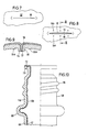
- FIG. 7 shows the area of the base 52 in which the squeezing process took place, immediately after the shaping process has ended within the closed blow mold in an embodiment which corresponds approximately to that of FIG. 5.
- a thin film 54 made of thermoplastic material of both sections 18, 20 remains in the area between the squeezing edges 22a, 22b, which film is generally torn off after the packaging has been removed from the blow mold with the waste piece 24 formed by the excess material.
- This ridge 56 also represents the parting plane for the two wall areas 44 and 46 of the outer container 40, in which they touch one another, but without being welded to one another.
- the recesses 62a, 62b or the projections 64 formed in them are, as can be seen in particular in FIG.
- the associated projections 64a, 64b are carried along with the result that the two opposite wall regions 44, 46 of the base 52 of the outer container 118 are pulled apart to form the opening 57.
- the projections 64a, 64b are carried along only over a short distance, since, owing to the elastic deformability of the thermoplastic material, the former jump out of the associated recesses 62a, 62b when a certain force acting on the projections is exceeded.
- FIG. 10 shows the neck 68 of a bottle-shaped packaging provided with an external thread 66.
- a circumferential bulge-shaped projection 69 is formed on the bottle neck, which, as shown in FIG. 10, leads to a form-fitting anchoring of the inner container 120 on the outer container 118, by means of which a relative displacement between the outer container and the inner container is prevented in the axial direction. Since the bottle neck normally remains free of filling material even when the packaging is filled to the maximum, there is no need for any movement or deformation of the inner container 120 in the region of the bottle neck, so that it does not matter if the bead 69 should also lead to greater dimensional stability of the inner container .
- the wall thickness of the inner container 120 may even be expedient to make the wall thickness of the inner container 120 thicker in the region of the neck 68 than in the region receiving the filling material, in order to prevent the inner container 42 from moving away from the outer container in the region of the neck 68 in the region of the neck 68 40 takes off.
- Fig. 10 also reveals that the neck-side end region of the inner tubular section 20 or the resulting wall of the inner container 42 is bent outwards in such a way that it covers the end boundary surface 70 of the outer container 40, thereby providing an additional positive connection between the outer container and the inner container is brought about.
- this end area 72 of the inner container 42 also serves as a sealing surface, which provides a perfect seal between the device 74 (FIG. 11) that can be screwed onto the neck 68 and the packaging.
- This device 74 is provided with a manually operable pump, by means of which a negative pressure can be generated in the inner container 42, so that, due to the pressure gradient which thus arises from the outside inwards, the atmospheric external pressure which flows through the opening 57 in the bottom of the outer container to the outside of the inner container 42 comes into effect, the latter is compressed with a reduction in volume and thus displacement of the filling material.
- the filling material is displaced in the direction of the bottle neck and the device 74 located thereon, which is provided with a suitable dispensing valve or the like.
- the package shown in Fig. 11 is provided with a dip tube 74 which extends close to the bottom of the package.
- the wall 120 of the inner container 42 is dimensioned and designed such that in the course of the emptying process the first Bottleneck 68 facing area of the inner container 42 is compressed by the pressure drop, this process continuing with increasing emptying downwards, i.e. towards the bottom 52. This can be done by a appropriate dimensioning and distribution of the thickness of the wall 120 of the inner container 42 can be achieved.
- the dip tube 76 is provided with at least one additional opening 88, which in the exemplary embodiment according to FIG. 1 is located in the central region of the dip tube 76.
- additional openings can also be provided in other areas of the immersion tube, for example near the bottom opening 78, so that if the bottom opening 78 is completely or partially closed by the wall 120 of the inner container 42 changing its position in the course of the emptying process, adequate emptying of the Allow inner container.
- the most complete possible emptying of the packaging is also favored by the fact that the volume decrease of the inner container takes place in a predetermined manner in such a way that in the emptied state the wall parts of the inner container pressed against each other due to the pressure gradient come as close as possible to each other so that only small dead spaces form, in which contents remain.
- FIG. 12 of the drawing Two possible designs are shown in FIG. 12 of the drawing.
- the wall 120 of the inner container 42 is provided with groove-like depressions 80 and 82 running parallel to the longitudinal axis, which represent weak zones along which the wall 120 folds along according to the intermediate stage shown in FIG. 12 of predetermined zones.
- Fig. 12 further shows that the grooves 80 on the inner and the grooves 82 on the outer boundary surface of the wall 42 favor folding to achieve extensive emptying. From the intermediate stage shown in dashed lines in FIG. 12 during the folding process, it follows that in the areas of the groove 80 arranged on the inside, the wall 142 moves inwards, that is to say on the dip tube 76, so that in the final state shown in FIG.
- the weak zones running parallel to the longitudinal axis of the packaging have been produced in such a way that the inside boundary of the wall 120 of the inner container 142 forms a polygon in cross-section, with corners 84 of the polygon in each case the zones of minimum wall thickness are located, which correspond to the grooves 80 and 82 of the embodiment shown in the lower part of FIG. 12.
- the outer container is made of PVC
- the inner container is made of polyethylene. Both materials are well suited for the functions intended for the two containers. Of course, other materials can also be used for both the outer container and the inner container.
Landscapes
- Engineering & Computer Science (AREA)
- Mechanical Engineering (AREA)
- Manufacturing & Machinery (AREA)
- Packages (AREA)
- Blow-Moulding Or Thermoforming Of Plastics Or The Like (AREA)
- Making Paper Articles (AREA)
- Closing Of Containers (AREA)
Claims (25)
Priority Applications (1)
| Application Number | Priority Date | Filing Date | Title |
|---|---|---|---|
| AT85113071T ATE55724T1 (de) | 1984-11-17 | 1985-10-15 | Verfahren zum herstellen einer mit einer verschliessbaren oeffnung versehenen verpackung und nach diesem verfahren hergestellte verpackung. |
Applications Claiming Priority (2)
| Application Number | Priority Date | Filing Date | Title |
|---|---|---|---|
| DE19843442092 DE3442092A1 (de) | 1984-11-17 | 1984-11-17 | Verfahren zum herstellen einer mit einer verschliessbaren oeffnung versehenen verpackung und nach diesem verfahren hergestellte verpackung |
| DE3442092 | 1984-11-17 |
Publications (3)
| Publication Number | Publication Date |
|---|---|
| EP0182094A2 EP0182094A2 (fr) | 1986-05-28 |
| EP0182094A3 EP0182094A3 (en) | 1987-12-02 |
| EP0182094B1 true EP0182094B1 (fr) | 1990-08-22 |
Family
ID=6250559
Family Applications (1)
| Application Number | Title | Priority Date | Filing Date |
|---|---|---|---|
| EP85113071A Expired - Lifetime EP0182094B1 (fr) | 1984-11-17 | 1985-10-15 | Procédé de fabrication d'un emballage muni d'une ouverture pouvant être refermée |
Country Status (3)
| Country | Link |
|---|---|
| EP (1) | EP0182094B1 (fr) |
| AT (1) | ATE55724T1 (fr) |
| DE (2) | DE3442092A1 (fr) |
Cited By (36)
| Publication number | Priority date | Publication date | Assignee | Title |
|---|---|---|---|---|
| US4930644A (en) * | 1988-12-22 | 1990-06-05 | Robbins Edward S Iii | Thin film container with removable lid and related process |
| WO1991007240A1 (fr) * | 1989-11-10 | 1991-05-30 | Imperial Chemical Industries Plc | Recipient |
| US5060816A (en) * | 1988-12-22 | 1991-10-29 | Robbins Edward S Iii | Composite container and associated carrier |
| WO1992011187A1 (fr) * | 1990-12-17 | 1992-07-09 | The Coca-Cola Company | Systeme de recipient pour liquide |
| WO1992012926A1 (fr) * | 1991-01-23 | 1992-08-06 | Continental Pet Technologies, Inc. | Bouteille multicouche a couche interieure separable et procede de formation |
| US5156300A (en) * | 1990-02-22 | 1992-10-20 | The Procter & Gamble Company | Bag-in-squeeze-bottle fluid dispenser with unsealed fluid passage |
| US5156299A (en) * | 1990-03-19 | 1992-10-20 | The Procter & Gamble Company | Pump-type dispenser package with flexible disposable recharge |
| FR2679526A1 (fr) * | 1991-07-25 | 1993-01-29 | Cebal | Tube en matiere plastique a tete fixee sur une jupe comprenant une couche exterieure semi-rigide munie de porosites traversantes ou de perforations. |
| EP0532873A1 (fr) * | 1991-09-18 | 1993-03-24 | GAPLAST GmbH | Récipient |
| FR2685285A1 (fr) * | 1991-12-20 | 1993-06-25 | Givenchy Parfums | Procede de conditionnement d'un produit liquide quelconque et flacon obtenu par ce procede. |
| US5261565A (en) * | 1992-06-11 | 1993-11-16 | The Procter & Gamble Company | Thin film beam spring vent valve |
| US5271153A (en) * | 1992-06-11 | 1993-12-21 | The Procter & Gamble Company | Apparatus for assembling a thin film beam spring vent valve |
| US5277015A (en) * | 1992-06-11 | 1994-01-11 | The Procter & Gamble Company | Method and apparatus for inserting a bag into a bottle |
| US5282304A (en) * | 1992-06-11 | 1994-02-01 | The Procter & Gamble Company | Method for assembling a thin-film beam spring valve |
| US5305920A (en) * | 1991-11-20 | 1994-04-26 | The Procter & Gamble Company | Bag-in-bottle package with reusable resilient squeeze bottle and disposable inner receptacle which inverts upon emptying without attachment near its midpoint to squeeze bottle |
| US5305921A (en) * | 1991-12-18 | 1994-04-26 | The Procter & Gamble Company | Package with replaceable inner receptacle having large integrally molded fitment |
| US5344045A (en) * | 1990-12-17 | 1994-09-06 | The Coca-Cola Company | Liquid container system |
| US5381927A (en) * | 1990-12-17 | 1995-01-17 | The Coca-Cola Company | Method of dispensing from a liquid container system |
| AU666324B2 (en) * | 1991-08-05 | 1996-02-08 | Yoshino Kogyosho Co., Ltd. | Bottle of laminate structure and method of making said bottle |
| US5711454A (en) * | 1992-05-11 | 1998-01-27 | Yoshino Kogyosho Co., Ltd. | Laminated bottle and pump device therefor |
| US5780129A (en) * | 1994-01-11 | 1998-07-14 | Nippon Steel Chemical Co., Ltd. | Multi-layer blow-molded article |
| US5799809A (en) * | 1995-02-16 | 1998-09-01 | Yoshino Kogyosho Co., Ltd. | Blow molded container and blow mold thereof |
| US5921416A (en) * | 1993-05-07 | 1999-07-13 | Nissei Asb Machine Co., Ltd. | Double-wall bottle and method and apparatus for molding the same |
| DE19626967C2 (de) * | 1996-07-04 | 1999-08-12 | Gaplast Gmbh | Verfahren zur Herstellung eines Behälters sowie Behälter mit Druckausgleichsöffnungen |
| US6083450A (en) | 1997-02-28 | 2000-07-04 | Owens-Brockway Plastic Products Inc. | Multilayer container package |
| US6109468A (en) * | 1996-07-04 | 2000-08-29 | Gaplast Gmbh | Container with pressure compensation holes |
| US6179142B1 (en) | 1998-04-13 | 2001-01-30 | The Coca-Cola Company | Wire-frame bottle and method of manufacturing same |
| US6276558B1 (en) * | 1997-08-30 | 2001-08-21 | Gaplast Gmbh | Method for producing a container and container with pressure equalization openings |
| EP1165246A1 (fr) | 1999-03-30 | 2002-01-02 | VG Emballage | Poche et ensemble de conditionnement et de distribution |
| FR2820121A1 (fr) * | 2001-01-30 | 2002-08-02 | Oreal | Flacon pompe a utilisation multidirectionnelle |
| US6440352B1 (en) * | 1995-04-17 | 2002-08-27 | Canon Kabushiki Kaisha | Liquid accommodating container providing negative pressure, manufacturing method for the same, ink jet cartridge having the container and ink jet recording head as a unit, and ink jet recording apparatus |
| US6670007B1 (en) | 1999-04-07 | 2003-12-30 | Owens-Brockway Plastic Products Inc. | Multilayer container |
| US7837927B2 (en) | 2003-04-02 | 2010-11-23 | Promens Sa | Method for carrying out ventilation in a multi-walled container |
| US7963955B2 (en) | 1998-02-27 | 2011-06-21 | Boehringer Ingelheim International Gmbh | Container for a medicinal liquid |
| US20220410461A1 (en) * | 2021-06-23 | 2022-12-29 | Gaplast Gmbh | Method of manufacturing a container |
| US12458990B2 (en) | 2022-04-06 | 2025-11-04 | Lumson S.P.A. | Fluid substance dispensing device |
Families Citing this family (26)
| Publication number | Priority date | Publication date | Assignee | Title |
|---|---|---|---|---|
| DE3723006A1 (de) * | 1987-07-11 | 1989-01-19 | Koetke Claus Dieter | Verfahren und vorrichtung zur herstellung von duennwandigen elastischen behaeltern |
| DE4322514C2 (de) * | 1993-07-06 | 1997-02-20 | Gaplast Ges Fuer Kunststoffver | Verfahren zur Herstellung eines Behälters mit flexiblem Innenbeutel |
| DE19615422A1 (de) | 1996-04-19 | 1997-11-20 | Boehringer Ingelheim Kg | Zweikammer-Kartusche für treibgasfreie Dosieraerosole |
| CN1064305C (zh) * | 1996-05-30 | 2001-04-11 | 株式会社吉野工业所 | 具有圆筒形筒体的挤出吹塑成形容器及其成形用金属模 |
| DE19706797A1 (de) * | 1997-02-20 | 1998-08-27 | Kourtoglou Sa | Verfahren zur Herstellung von Verpackungsbehältern aus Kunststoff sowie Formstation für einen Kunststoff-Verpackungsbehälter, Verpackungsmaschine und Kunststoff-Verpackungsbehälter, insbesondere hergestellt nach dem vorgenannten Verfahren, sowie Verfahren zur Herstellung befüllter und verschlossener Verpackungsbehälter |
| EP0893356A1 (fr) | 1997-07-23 | 1999-01-27 | The Procter & Gamble Company | Récipient multicouche résistant à la pression |
| DE19808295A1 (de) * | 1998-02-27 | 1999-11-11 | Boehringer Ingelheim Int | Behälter für eine medizinische Flüssigkeit |
| US6685691B1 (en) | 1998-02-27 | 2004-02-03 | Boehringer Ingelheim Gmbh | Container for a medicinal liquid |
| DE19851404A1 (de) | 1998-11-07 | 2000-05-11 | Boehringer Ingelheim Int | Druckausgleichsvorrichtung für einen Doppelbehälter |
| JP3464405B2 (ja) * | 1999-02-18 | 2003-11-10 | 阪神化成工業株式会社 | 多層薄肉容器 |
| DE19940713A1 (de) | 1999-02-23 | 2001-03-01 | Boehringer Ingelheim Int | Kartusche für eine Flüssigkeit |
| DE19958577A1 (de) * | 1999-12-04 | 2001-06-07 | Boehringer Ingelheim Pharma | Verfahren zur Herstellung von zweischichtigen Behältern |
| DE10017443A1 (de) * | 2000-04-07 | 2001-10-25 | Boehringer Ingelheim Pharma | Verfahren zum Herstellen eines mit einer Druckausgleichsöffnung versehenen Behälters und nach diesem Verfahren hergestellter Behälter |
| US6921385B2 (en) | 2002-08-05 | 2005-07-26 | Alcon, Inc. | Apparatus for delivery of fluid to opthalmic surgical handpiece |
| DE10256015B4 (de) * | 2002-11-30 | 2005-04-14 | Gaplast Gmbh | Verfahren zur Herstellung eines Behälters mit wenigstens einer Druckausgleichsöffnung |
| DE10347907A1 (de) | 2003-10-15 | 2005-05-25 | Bernd Hansen | Verfahren und Vorrichtung zur Herstellung gefüllter und verschlossener Behälter |
| DE202005014895U1 (de) | 2005-04-18 | 2006-08-24 | Megaplast Gmbh & Co. Kg | Spender zur Ausgabe flüssiger bis pastöser Massen |
| CN100571892C (zh) * | 2005-04-18 | 2009-12-23 | 大型塑胶制品两合公司 | 用于排出液态至浆状物料的分配器 |
| DE102010024980B4 (de) | 2010-06-24 | 2012-04-26 | Gaplast Gmbh | Behälter mit Innenbeutel |
| DE102014113535B4 (de) | 2014-09-19 | 2017-12-21 | Inotech Kunstofftechnik Gmbh | Spender mit Beutel |
| EP3220852B1 (fr) | 2014-11-20 | 2026-03-25 | Boehringer Ingelheim Vetmedica GmbH | Récipient pour inhalateur |
| PL3299144T3 (pl) * | 2016-09-26 | 2020-05-18 | Boehringer Ingelheim International Gmbh | Sposób sprawdzania szczelności torebki w przestrzeni wewnętrznej pojemnika |
| JP7310412B2 (ja) * | 2018-11-15 | 2023-07-19 | アルテミラ製缶株式会社 | 缶及びその製造方法 |
| JP7322492B2 (ja) * | 2019-04-26 | 2023-08-08 | 東洋製罐グループホールディングス株式会社 | 容器及びそのプリフォーム |
| DE102020129996B3 (de) * | 2020-11-13 | 2022-03-03 | Gaplast Gmbh | Verfahren zur Herstellung von Behältern |
| CN119611941A (zh) * | 2025-01-20 | 2025-03-14 | 浙江瑞昶实业有限公司 | 一种内袋收缩瓶及其加工方法 |
Family Cites Families (7)
| Publication number | Priority date | Publication date | Assignee | Title |
|---|---|---|---|---|
| US3118572A (en) * | 1962-09-04 | 1964-01-21 | Koppers Co Inc | Squeeze bottle |
| US3940001A (en) * | 1972-10-06 | 1976-02-24 | Ethyl Corporation | Recyclable plastic containers |
| US4008830A (en) * | 1973-08-10 | 1977-02-22 | Philip Meshberg | Liquid dispenser using a non vented pump and a collapsible plastic bag |
| GB1455453A (en) * | 1973-11-13 | 1976-11-10 | Petterson T H | Barrier package and method of manufacture |
| SE414486B (sv) * | 1977-05-13 | 1980-08-04 | Plm Ab | Behallare for ljuskensligt gods |
| DE3009463A1 (de) * | 1980-03-12 | 1981-09-17 | Kautex Werke Reinold Hagen Gmbh, 5300 Bonn | Verfahren zum herstellen von hohlkoerpern aus kunststoff |
| US4423829A (en) * | 1980-08-28 | 1984-01-03 | Container Industries Inc. | Apparatus for containing and dispensing fluids under pressure and method of manufacturing same |
-
1984
- 1984-11-17 DE DE19843442092 patent/DE3442092A1/de not_active Withdrawn
-
1985
- 1985-10-15 AT AT85113071T patent/ATE55724T1/de not_active IP Right Cessation
- 1985-10-15 DE DE8585113071T patent/DE3579293D1/de not_active Expired - Lifetime
- 1985-10-15 EP EP85113071A patent/EP0182094B1/fr not_active Expired - Lifetime
Cited By (51)
| Publication number | Priority date | Publication date | Assignee | Title |
|---|---|---|---|---|
| US4930644A (en) * | 1988-12-22 | 1990-06-05 | Robbins Edward S Iii | Thin film container with removable lid and related process |
| US5060816A (en) * | 1988-12-22 | 1991-10-29 | Robbins Edward S Iii | Composite container and associated carrier |
| WO1991007240A1 (fr) * | 1989-11-10 | 1991-05-30 | Imperial Chemical Industries Plc | Recipient |
| US5156300A (en) * | 1990-02-22 | 1992-10-20 | The Procter & Gamble Company | Bag-in-squeeze-bottle fluid dispenser with unsealed fluid passage |
| US5156299A (en) * | 1990-03-19 | 1992-10-20 | The Procter & Gamble Company | Pump-type dispenser package with flexible disposable recharge |
| US5385269A (en) * | 1990-12-17 | 1995-01-31 | The Coca-Cola Company | Liquid container system |
| US5381927A (en) * | 1990-12-17 | 1995-01-17 | The Coca-Cola Company | Method of dispensing from a liquid container system |
| US5242085A (en) * | 1990-12-17 | 1993-09-07 | The Coca-Cola Company | Liquid container system |
| US5344045A (en) * | 1990-12-17 | 1994-09-06 | The Coca-Cola Company | Liquid container system |
| US5242086A (en) * | 1990-12-17 | 1993-09-07 | The Coca-Cola Company | Liquid container system |
| US5433347A (en) * | 1990-12-17 | 1995-07-18 | The Coca-Cola Company | Liquid container system |
| WO1992011187A1 (fr) * | 1990-12-17 | 1992-07-09 | The Coca-Cola Company | Systeme de recipient pour liquide |
| US5383576A (en) * | 1990-12-17 | 1995-01-24 | The Coca-Cola Company | Liquid container system |
| US5301838A (en) * | 1991-01-23 | 1994-04-12 | Continental Pet Technologies, Inc. | Multilayer bottle with separable inner layer and method for forming same |
| WO1992012926A1 (fr) * | 1991-01-23 | 1992-08-06 | Continental Pet Technologies, Inc. | Bouteille multicouche a couche interieure separable et procede de formation |
| US5407629A (en) * | 1991-01-23 | 1995-04-18 | Continental Pet Technologies, Inc. | Multilayer bottle with separable inner layer and method of forming same |
| FR2679526A1 (fr) * | 1991-07-25 | 1993-01-29 | Cebal | Tube en matiere plastique a tete fixee sur une jupe comprenant une couche exterieure semi-rigide munie de porosites traversantes ou de perforations. |
| AU666324B2 (en) * | 1991-08-05 | 1996-02-08 | Yoshino Kogyosho Co., Ltd. | Bottle of laminate structure and method of making said bottle |
| AU689002B2 (en) * | 1991-08-05 | 1998-03-19 | Yoshino Kogyosho Co., Ltd. | Multilayer bottle and a method of manufacturing the same |
| US5567377A (en) * | 1991-08-05 | 1996-10-22 | Yoshino Kogyosho Co., Ltd. | Method of manufacturing a multilayer bottle |
| DE4139555A1 (de) * | 1991-09-18 | 1993-03-25 | Gaplast Gmbh | Behaelter |
| US5447678A (en) * | 1991-09-18 | 1995-09-05 | Kneer; Roland | Method for making a container with an inner deformable bag |
| EP0532873A1 (fr) * | 1991-09-18 | 1993-03-24 | GAPLAST GmbH | Récipient |
| US5305920A (en) * | 1991-11-20 | 1994-04-26 | The Procter & Gamble Company | Bag-in-bottle package with reusable resilient squeeze bottle and disposable inner receptacle which inverts upon emptying without attachment near its midpoint to squeeze bottle |
| US5377875A (en) | 1991-12-18 | 1995-01-03 | The Procter & Gamble Company | Package with replaceable inner receptacle having large integrally molded fitment |
| US5305921A (en) * | 1991-12-18 | 1994-04-26 | The Procter & Gamble Company | Package with replaceable inner receptacle having large integrally molded fitment |
| FR2685285A1 (fr) * | 1991-12-20 | 1993-06-25 | Givenchy Parfums | Procede de conditionnement d'un produit liquide quelconque et flacon obtenu par ce procede. |
| US5921438A (en) * | 1992-05-11 | 1999-07-13 | Yoshino Kogyosho Co., Ltd. | Laminated bottle and pump device therefor |
| US5711454A (en) * | 1992-05-11 | 1998-01-27 | Yoshino Kogyosho Co., Ltd. | Laminated bottle and pump device therefor |
| US5261565A (en) * | 1992-06-11 | 1993-11-16 | The Procter & Gamble Company | Thin film beam spring vent valve |
| US5282304A (en) * | 1992-06-11 | 1994-02-01 | The Procter & Gamble Company | Method for assembling a thin-film beam spring valve |
| US5277015A (en) * | 1992-06-11 | 1994-01-11 | The Procter & Gamble Company | Method and apparatus for inserting a bag into a bottle |
| US5271153A (en) * | 1992-06-11 | 1993-12-21 | The Procter & Gamble Company | Apparatus for assembling a thin film beam spring vent valve |
| US5921416A (en) * | 1993-05-07 | 1999-07-13 | Nissei Asb Machine Co., Ltd. | Double-wall bottle and method and apparatus for molding the same |
| US5780129A (en) * | 1994-01-11 | 1998-07-14 | Nippon Steel Chemical Co., Ltd. | Multi-layer blow-molded article |
| US5799809A (en) * | 1995-02-16 | 1998-09-01 | Yoshino Kogyosho Co., Ltd. | Blow molded container and blow mold thereof |
| US6440352B1 (en) * | 1995-04-17 | 2002-08-27 | Canon Kabushiki Kaisha | Liquid accommodating container providing negative pressure, manufacturing method for the same, ink jet cartridge having the container and ink jet recording head as a unit, and ink jet recording apparatus |
| DE19626967C2 (de) * | 1996-07-04 | 1999-08-12 | Gaplast Gmbh | Verfahren zur Herstellung eines Behälters sowie Behälter mit Druckausgleichsöffnungen |
| US6109468A (en) * | 1996-07-04 | 2000-08-29 | Gaplast Gmbh | Container with pressure compensation holes |
| US6244852B1 (en) * | 1996-07-04 | 2001-06-12 | Gaplast Gmbh | Method of producing a receptacle and a receptacle having pressure compensating openings |
| US6083450A (en) | 1997-02-28 | 2000-07-04 | Owens-Brockway Plastic Products Inc. | Multilayer container package |
| US6238201B1 (en) | 1997-02-28 | 2001-05-29 | Owens-Brockway Plastic Products Inc. | Multilayer container package molding apparatus |
| US6276558B1 (en) * | 1997-08-30 | 2001-08-21 | Gaplast Gmbh | Method for producing a container and container with pressure equalization openings |
| US7963955B2 (en) | 1998-02-27 | 2011-06-21 | Boehringer Ingelheim International Gmbh | Container for a medicinal liquid |
| US6179142B1 (en) | 1998-04-13 | 2001-01-30 | The Coca-Cola Company | Wire-frame bottle and method of manufacturing same |
| EP1165246A1 (fr) | 1999-03-30 | 2002-01-02 | VG Emballage | Poche et ensemble de conditionnement et de distribution |
| US6670007B1 (en) | 1999-04-07 | 2003-12-30 | Owens-Brockway Plastic Products Inc. | Multilayer container |
| FR2820121A1 (fr) * | 2001-01-30 | 2002-08-02 | Oreal | Flacon pompe a utilisation multidirectionnelle |
| US7837927B2 (en) | 2003-04-02 | 2010-11-23 | Promens Sa | Method for carrying out ventilation in a multi-walled container |
| US20220410461A1 (en) * | 2021-06-23 | 2022-12-29 | Gaplast Gmbh | Method of manufacturing a container |
| US12458990B2 (en) | 2022-04-06 | 2025-11-04 | Lumson S.P.A. | Fluid substance dispensing device |
Also Published As
| Publication number | Publication date |
|---|---|
| DE3442092A1 (de) | 1986-05-28 |
| DE3579293D1 (de) | 1990-09-27 |
| EP0182094A3 (en) | 1987-12-02 |
| ATE55724T1 (de) | 1990-09-15 |
| EP0182094A2 (fr) | 1986-05-28 |
Similar Documents
| Publication | Publication Date | Title |
|---|---|---|
| EP0182094A2 (fr) | Procédé de fabrication d'un emballage muni d'une ouverture pouvant être refermée | |
| EP2585377B1 (fr) | Contenant comportant un sac intérieur | |
| EP0557487B1 (fr) | Unite de fermeture de recipients de matieres coulantes | |
| DE69201437T2 (de) | Mehrschichtflasche mit einer trennbaren innenschicht. | |
| DE3853951T2 (de) | Kunststoffbehälter unter druck mit verbessertem ventil. | |
| DE69634313T2 (de) | Behälter aus laminiertem leicht trennbarem Material | |
| EP0612664B1 (fr) | Emballage pour produits fluides, procédé de fabrication d'un tel emballage et dispositif de réalisation du procédé | |
| DE69722463T2 (de) | Entnahmeverschluss mit stopfen sowie verfahren zu dessen herstellung | |
| DE69719219T2 (de) | Verpackungsbehälter und verfahren zu seiner herstellung | |
| DE60124291T2 (de) | Extrusions-blasgeformter zusammendrückbarer behälter und verfahren zu dessen herstellung | |
| DE69207244T2 (de) | Öffnungsvorrichtung für einen Verpackungsbehälter und Verfahren zu ihrer Herstellung | |
| EP0532873A1 (fr) | Récipient | |
| EP2069210B1 (fr) | Récipient de conditionnement et son procédé de fabrication | |
| DE69327305T2 (de) | Behälter mit henkel | |
| WO1998001366A1 (fr) | Recipient pourvu d'ouvertures d'equilibrage de la pression | |
| DE69311375T2 (de) | Aus mehreren tuben bestehender verpackungsbehälter und verfahren zu dessen herstellung | |
| DE3009463A1 (de) | Verfahren zum herstellen von hohlkoerpern aus kunststoff | |
| EP0375943B1 (fr) | Récipient pour fluides de ménage | |
| EP0720565A1 (fr) | Recipient en matiere thermoplastique et son procede de production | |
| EP0381627B1 (fr) | Distribution à deux chambres pour emballage sous pression ou non | |
| EP1027268A1 (fr) | Procede de production d'une bombe a aerosol presentant deux chambres, et dispositif pour mettre en oeuvre ledit procede | |
| DE69423536T2 (de) | Verfahren und Vorrichtung zur Herstellung eines Halteflansches um eine Behälteröffnung | |
| DE4403755A1 (de) | Austragvorrichtung für Medien | |
| DE2915228A1 (de) | Verpackungsbehaelter fuer fluessige und rieselfaehige produkte und verfahren zum herstellen des behaelters | |
| DE69415243T2 (de) | Flasche aus kunstharz |
Legal Events
| Date | Code | Title | Description |
|---|---|---|---|
| PUAI | Public reference made under article 153(3) epc to a published international application that has entered the european phase |
Free format text: ORIGINAL CODE: 0009012 |
|
| AK | Designated contracting states |
Kind code of ref document: A2 Designated state(s): AT BE CH DE FR GB IT LI LU NL SE |
|
| PUAL | Search report despatched |
Free format text: ORIGINAL CODE: 0009013 |
|
| AK | Designated contracting states |
Kind code of ref document: A3 Designated state(s): AT BE CH DE FR GB IT LI LU NL SE |
|
| 17P | Request for examination filed |
Effective date: 19880519 |
|
| 17Q | First examination report despatched |
Effective date: 19891012 |
|
| GRAA | (expected) grant |
Free format text: ORIGINAL CODE: 0009210 |
|
| ITF | It: translation for a ep patent filed | ||
| AK | Designated contracting states |
Kind code of ref document: B1 Designated state(s): AT BE CH DE FR GB IT LI LU NL SE |
|
| PG25 | Lapsed in a contracting state [announced via postgrant information from national office to epo] |
Ref country code: SE Free format text: THE PATENT HAS BEEN ANNULLED BY A DECISION OF A NATIONAL AUTHORITY Effective date: 19900822 |
|
| REF | Corresponds to: |
Ref document number: 55724 Country of ref document: AT Date of ref document: 19900915 Kind code of ref document: T |
|
| REF | Corresponds to: |
Ref document number: 3579293 Country of ref document: DE Date of ref document: 19900927 |
|
| GBT | Gb: translation of ep patent filed (gb section 77(6)(a)/1977) | ||
| ET | Fr: translation filed | ||
| PLBE | No opposition filed within time limit |
Free format text: ORIGINAL CODE: 0009261 |
|
| STAA | Information on the status of an ep patent application or granted ep patent |
Free format text: STATUS: NO OPPOSITION FILED WITHIN TIME LIMIT |
|
| 26N | No opposition filed | ||
| ITTA | It: last paid annual fee | ||
| EPTA | Lu: last paid annual fee | ||
| PGFP | Annual fee paid to national office [announced via postgrant information from national office to epo] |
Ref country code: LU Payment date: 19991014 Year of fee payment: 15 |
|
| PG25 | Lapsed in a contracting state [announced via postgrant information from national office to epo] |
Ref country code: LU Free format text: LAPSE BECAUSE OF NON-PAYMENT OF DUE FEES Effective date: 20001015 |
|
| REG | Reference to a national code |
Ref country code: GB Ref legal event code: IF02 |
|
| PGFP | Annual fee paid to national office [announced via postgrant information from national office to epo] |
Ref country code: GB Payment date: 20041005 Year of fee payment: 20 |
|
| PGFP | Annual fee paid to national office [announced via postgrant information from national office to epo] |
Ref country code: NL Payment date: 20041019 Year of fee payment: 20 Ref country code: FR Payment date: 20041019 Year of fee payment: 20 |
|
| PGFP | Annual fee paid to national office [announced via postgrant information from national office to epo] |
Ref country code: BE Payment date: 20041022 Year of fee payment: 20 Ref country code: AT Payment date: 20041022 Year of fee payment: 20 |
|
| PGFP | Annual fee paid to national office [announced via postgrant information from national office to epo] |
Ref country code: CH Payment date: 20041025 Year of fee payment: 20 |
|
| PGFP | Annual fee paid to national office [announced via postgrant information from national office to epo] |
Ref country code: DE Payment date: 20041229 Year of fee payment: 20 |
|
| PG25 | Lapsed in a contracting state [announced via postgrant information from national office to epo] |
Ref country code: GB Free format text: LAPSE BECAUSE OF EXPIRATION OF PROTECTION Effective date: 20051014 |
|
| PG25 | Lapsed in a contracting state [announced via postgrant information from national office to epo] |
Ref country code: NL Free format text: LAPSE BECAUSE OF EXPIRATION OF PROTECTION Effective date: 20051015 |
|
| BE20 | Be: patent expired |
Owner name: *KAUTEX-WERKE REINOLD HAGEN A.G. Effective date: 20051015 |
|
| REG | Reference to a national code |
Ref country code: GB Ref legal event code: PE20 |
|
| REG | Reference to a national code |
Ref country code: CH Ref legal event code: PL |
|
| NLV7 | Nl: ceased due to reaching the maximum lifetime of a patent |
Effective date: 20051015 |
|
| BE20 | Be: patent expired |
Owner name: *KAUTEX-WERKE REINOLD HAGEN A.G. Effective date: 20051015 |