EP0182143A2 - Vorrichtung zur Steuerung des Gasabzuges aus einer Mülldeponie und Verfahren hierzu - Google Patents
Vorrichtung zur Steuerung des Gasabzuges aus einer Mülldeponie und Verfahren hierzu Download PDFInfo
- Publication number
- EP0182143A2 EP0182143A2 EP85113525A EP85113525A EP0182143A2 EP 0182143 A2 EP0182143 A2 EP 0182143A2 EP 85113525 A EP85113525 A EP 85113525A EP 85113525 A EP85113525 A EP 85113525A EP 0182143 A2 EP0182143 A2 EP 0182143A2
- Authority
- EP
- European Patent Office
- Prior art keywords
- gas
- measuring
- collector
- decomposition gases
- content
- Prior art date
- Legal status (The legal status is an assumption and is not a legal conclusion. Google has not performed a legal analysis and makes no representation as to the accuracy of the status listed.)
- Granted
Links
Images

Classifications
-
- B—PERFORMING OPERATIONS; TRANSPORTING
- B09—DISPOSAL OF SOLID WASTE; RECLAMATION OF CONTAMINATED SOIL
- B09B—DISPOSAL OF SOLID WASTE NOT OTHERWISE PROVIDED FOR
- B09B1/00—Dumping solid waste
-
- E—FIXED CONSTRUCTIONS
- E21—EARTH OR ROCK DRILLING; MINING
- E21B—EARTH OR ROCK DRILLING; OBTAINING OIL, GAS, WATER, SOLUBLE OR MELTABLE MATERIALS OR A SLURRY OF MINERALS FROM WELLS
- E21B43/00—Methods or apparatus for obtaining oil, gas, water, soluble or meltable materials or a slurry of minerals from wells
-
- Y—GENERAL TAGGING OF NEW TECHNOLOGICAL DEVELOPMENTS; GENERAL TAGGING OF CROSS-SECTIONAL TECHNOLOGIES SPANNING OVER SEVERAL SECTIONS OF THE IPC; TECHNICAL SUBJECTS COVERED BY FORMER USPC CROSS-REFERENCE ART COLLECTIONS [XRACs] AND DIGESTS
- Y02—TECHNOLOGIES OR APPLICATIONS FOR MITIGATION OR ADAPTATION AGAINST CLIMATE CHANGE
- Y02E—REDUCTION OF GREENHOUSE GAS [GHG] EMISSIONS, RELATED TO ENERGY GENERATION, TRANSMISSION OR DISTRIBUTION
- Y02E50/00—Technologies for the production of fuel of non-fossil origin
- Y02E50/30—Fuel from waste, e.g. synthetic alcohol or diesel
-
- Y—GENERAL TAGGING OF NEW TECHNOLOGICAL DEVELOPMENTS; GENERAL TAGGING OF CROSS-SECTIONAL TECHNOLOGIES SPANNING OVER SEVERAL SECTIONS OF THE IPC; TECHNICAL SUBJECTS COVERED BY FORMER USPC CROSS-REFERENCE ART COLLECTIONS [XRACs] AND DIGESTS
- Y02—TECHNOLOGIES OR APPLICATIONS FOR MITIGATION OR ADAPTATION AGAINST CLIMATE CHANGE
- Y02W—CLIMATE CHANGE MITIGATION TECHNOLOGIES RELATED TO WASTEWATER TREATMENT OR WASTE MANAGEMENT
- Y02W30/00—Technologies for solid waste management
- Y02W30/30—Landfill technologies aiming to mitigate methane emissions
-
- Y—GENERAL TAGGING OF NEW TECHNOLOGICAL DEVELOPMENTS; GENERAL TAGGING OF CROSS-SECTIONAL TECHNOLOGIES SPANNING OVER SEVERAL SECTIONS OF THE IPC; TECHNICAL SUBJECTS COVERED BY FORMER USPC CROSS-REFERENCE ART COLLECTIONS [XRACs] AND DIGESTS
- Y10—TECHNICAL SUBJECTS COVERED BY FORMER USPC
- Y10S—TECHNICAL SUBJECTS COVERED BY FORMER USPC CROSS-REFERENCE ART COLLECTIONS [XRACs] AND DIGESTS
- Y10S210/00—Liquid purification or separation
- Y10S210/901—Specified land fill feature, e.g. prevention of ground water fouling
-
- Y—GENERAL TAGGING OF NEW TECHNOLOGICAL DEVELOPMENTS; GENERAL TAGGING OF CROSS-SECTIONAL TECHNOLOGIES SPANNING OVER SEVERAL SECTIONS OF THE IPC; TECHNICAL SUBJECTS COVERED BY FORMER USPC CROSS-REFERENCE ART COLLECTIONS [XRACs] AND DIGESTS
- Y10—TECHNICAL SUBJECTS COVERED BY FORMER USPC
- Y10T—TECHNICAL SUBJECTS COVERED BY FORMER US CLASSIFICATION
- Y10T156/00—Adhesive bonding and miscellaneous chemical manufacture
- Y10T156/10—Methods of surface bonding and/or assembly therefor
- Y10T156/1052—Methods of surface bonding and/or assembly therefor with cutting, punching, tearing or severing
Definitions
- the invention relates to a method for controlling the gas extraction from a landfill according to the preamble of claim 1 and an apparatus for performing the method.
- decomposition gases which largely consist of methane gas, are generated by rotting. Methane is a flammable gas that can cause a landfill fire. Methane can also cause explosions. Penetrates z. B. methane in closed rooms, there is a risk of explosion with a 5 - 15% CH 4 content in the air. If the decomposition gases escape into the soil surrounding the landfill, the methane damages the plants. Efforts are therefore made to remove the decomposition gases and to make them usable for energetic purposes or to burn them off.
- the invention is based, to extract the decomposition gases from a landfill in a controlled manner, on the one hand to prevent air from entering the refuse and on the other hand to prevent the decomposition gases from escaping uncontrollably from the landfill, the extracted decomposition gases being supposed to have a methane content which is optimal at all times technical use guaranteed.
- a device for performing this method is specified in claim 2.
- the decomposition gases can be sucked off in a controlled manner in such a way that air ingress on the one hand and uncontrolled escape of the decomposition gases on the other hand is avoided.
- the methane content of the decomposition gases fed into the pressure line to the consumer can be kept approximately the same in narrow areas, so that excellent, optimal technical use is possible.
- the control of the extracted gas volume flow ensures that only as much gas is extracted as the bacteria produce. This ensures a high quality gas with a largely constant methane content, which can also be relatively low under certain circumstances.
- the specifiable uniformity of the methane content is crucial for many consumers, since it is not necessary to adapt the gas engines, burners or the like fed with the decomposition gases to different qualities of the gas.
- the shut-off elements are preferably arranged in each gas suction line in the area of the collector, wherein the sensors can be arranged in front of or behind each shut-off element in the flow direction. It can also be advantageous to arrange the sensor assigned to a gas suction line in the gas collector corresponding to the suction line. If the sensors determine the 0 2 content of the gas flowing through, the measuring and control device will actuate the shut-off device of the same gas line assigned to the sensor in the closing direction when the 0 2 content increases (e.g. in the event of air ingress) and throttle the volume flow of the gas until the 0 2 content has fallen below the limit again. Falls over the course of further gas extraction of the 0 2 value below a predetermined minimum limit value (e.g.
- the measuring and control device will open the associated shut-off device in the same gas extraction line in order to increase the extracted gas volume flow until the specified one minimum limit is exceeded again.
- Such a measurement and control process can also be advantageous based on the N, Co 2 or CH 4 values in the extracted cerium . settlement gas can be controlled.
- the data reported to the measuring and regulating device can be fed, preferably digitized, to an operating center via an external line.
- an operating center possibly 100 km to 500 km away, several landfill control centers can be monitored, which essentially consists of the measuring and control device with the associated sensors and shut-off devices.
- an alarm device can be connected to the measuring and regulating device, which is preferably integrated in the housing of the measuring and regulating device. The alarm signal can also be transmitted directly to the operations center and displayed there.
- the landfill control center is preferably arranged in a steel container which can be placed at a convenient location at a predeterminable distance from the landfill. In this way, the control center is easily interchangeable, particularly in the event of a malfunction, so that the extraction of the decomposition gases from the landfill is continuously ensured without major interruption. Furthermore, the containers can advantageously be completely installed at the factory.
- the landfill 1 shown in FIG. 1 is piled up on preferably leveled ground 2.
- a largely gas-tight tarpaulin 3, preferably made of PVC, is spread out on the floor, onto which the garbage 7 is poured.
- the heaped rubbish pile is also covered with a largely gas-tight tarpaulin 4, preferably made of PVC, the edges 5 of the tarpaulins 3 and 4 being glued or welded to one another in a gastight manner, so that an essentially gastight chamber for the rubbish 7 is formed.
- An earth cover 6 is applied to the tarpaulin.
- the landfill 1 has a height H of approximately 10 m to 50 m, the earth cover 6 having a thickness of approximately 1 m to 2 m.
- the side walls of landfill 1 preferably have a slope angle of approximately 35 °.
- the width B of the landfill 1 measured directly above the floor 2 is approximately 100 m to 500 m.
- gas wells 8 which extend over the entire height of the mountain of waste, are preferably provided as gas collectors 8.
- the number of gas wells 8 is selected according to the size of the landfill, the type of waste 7 and the expected quantity of decomposition gases.
- three gas wells are arranged at a distance from one another in the section shown, which are designated in detail by 8.1, 8.2 and 8.3.
- Each of the gas wells 8 is assigned a gas suction line 9 or 9.1, 9.2, 9.3, one end of which projects into a gas well 8 approximately centrally to approximately half the height.
- Horizontal drainages can also be provided as gas collectors.
- the individual gas extraction lines 9.1 to 9.3 run just below the tarpaulin 4 along the ceiling and an embankment of the landfill 1 and are guided into the soil of the floor 2, for which purpose they are carried out gastight through the floor tarpaulin 3 in the region of their edge.
- the lines 9.1 to 9.3 are arranged one behind the other in the sectional plane. It may be appropriate to cut the lines to be level on top of each other.
- the gas extraction lines 9 are fed - preferably lying in the ground - to a control center 19 which is provided in a building 20 or a remote container 21 (FIG. 2) erected at a freely selectable distance E from the landfill 1.
- the building or container is preferably set up near the landfill.
- the lines 9 are led from below into the building 20 or the container 21 and open > ' via shut-off devices 11 or 11.1, 11.2, 11.3 in a collector designed as a tube 12.
- a conveying device 13 a pump, a blower, a compressor or the like
- the decomposition gases are sucked out of the gas well 8 and fed to a consumer for technical use via a pressure line 14 in the direction of the arrow 15.
- the gas extraction lines 9 are preferably made of PVC and have a diameter of 60 mm to 150 mm.
- the pressure line 14 fed from the conveyor device 13 to the consumer preferably has a diameter of approximately 100 mm to 300 mm.
- the gas produced during the decomposition of the waste has a high proportion of methane and penetrates through the gas-permeable walls of the gas wells 8 and is sucked off by a vacuum. If the vacuum is too high, the not always sealed covers (earth cover or tarpaulins 3 and 4) suck ambient air and thus oxygen into the waste 7, which is harmful for the bacteria releasing the methane gas, since the oxygen restricts or even destroys their living conditions. The delivery rate of methane gas can drop considerably.
- a sensor 10.1, 10.2 and 10.3 are arranged in each line 9 in the flow direction of the gas behind the shut-off elements 11.1, 11.2 and 1.1.3 designed as control valves.
- B. measures the concentration of nitrogen (N), carbon dioxide (C0 2 ), methane (CHg), preferably the oxygen concentration (O 2 ) of the decomposition gases flowing through.
- the sensors 10 give the N-, CO 2 -, CH 4 or r 0 2 concentration corresponding signals from which are supplied via electrical lines 16 to a measuring and control device 17th
- This measuring and control device 17 controls the control valves 11 as a function of the determined measured values via control lines 18 in order to automatically regulate the volume flow of the decomposition gases extracted from a gas well 8.
- the output signals of the sensors 10 can be continuously recorded by the measuring and control device 17 in order to immediately initiate appropriate countermeasures (closed control loop).
- the sensors can be advantageous for reducing the electronic expenditure in the measuring and control device 17 to be queried only once within certain time intervals and to actuate the corresponding control valve 11 via the corresponding control lines 18.
- the sensor 10.1 z. B the oxygen content (0 2 content) of the extracted decomposition gases and reports this via an electrical line 16 to the measuring and control device 17.
- the measuring and control device 17 reduces the corresponding control valve 11 the passage cross-section of the associated gas line 9, whereby the amount of gas extracted is reduced until the oxygen content falls below the predetermined maximum limit again.
- the measuring and control device 17 causes the associated control valve 11 to open in order to increase the amount of gas extracted until the determined 0 2 value again falls within the range of the predetermined one Limits.
- the O 2 content of the extracted decomposition gas is kept within predetermined limit values, as a result of which the quality of the extracted gas, ie its proportion of methane (CH 4 ), can be kept relatively high and constant.
- the extracted gas can therefore be used technically optimally by the consumer.
- N content nitrogen content
- CO 2 - or CH 4 content it may also be appropriate, optionally or in addition to the determination of the ° 2 content z. B. to detect the N content (nitrogen content), CO 2 - or CH 4 content and to control the amount of gas extracted using these variables.
- the limit values to be specified as comparison values are set via input elements 27 on the measuring and control device 17. With the measuring and control device 17, errors can also be detected. An air intrusion into a gas well can be detected by permanently exceeding the predetermined O 2 limit value, because despite countermeasures initiated by the measuring and control device 17 (closing the control valve), the 0 2 value will not drop below the predetermined maximum limit value.
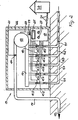
- FIG. 2 shows a steel container 21 which is provided with corresponding connections for the electrical lines and gas lines provided.
- the container 21 can thus be brought to any place of use without extensive construction measures being required.
- the container can be manufactured ready for use in a factory.
- FIG. 2 In the exemplary embodiment according to FIG. 2, five gas extraction lines 9.1 to 9.5 are shown, via which the decomposition gases are extracted from gas wells, not shown, according to FIG. 1.
- 12 control valves 11.1 to 11.5 are arranged in each line before entering the collecting tube.
- the sensors for determining the 0 2 content (N content, etc.) are arranged upstream of the valves here.
- the gas extraction is controlled as already described.
- the measuring and control device 17 is also provided with a display 25, by means of which the quantity and the energy content of the gas conveyed in the pressure line 14 can be displayed.
- the measuring and regulating device receives the values required for this from a flow meter 24 arranged in the pressure line, the output signal of which is fed via a line 22 to the measuring and regulating device 17.
- the values determined by the sensors 10.1 to 10.5 and / or the amount of the conveyed gas are fed via a line 26 to an operating center, not shown, which monitors several control centers 19 and the values reported by them for statistical evaluations, consumption determination etc. stores and further processed.
- the control center can also use the transmitted data to detect errors.
- the operations center can e.g. B. 100 km to 500 km or further away from the landfill 1, since only electrical signals are to be transmitted. For interference-free transmission, it can be advantageous to digitize the signals.
- the measurement values obtained in the control center 19 are preferably stored and z. B. remotely transmitted only once a day or in other freely selectable time intervals of the operations center. In topographically unfavorable conditions, it may be expedient to transmit the data to the operating center by radio instead of via a line 26.
- the delivery rate of the delivery device 13 in accordance with the gas quantity required by the consumer.
- 17 funding via line 26 of the measuring and control device benefits are specified.
- the measuring and regulating device will then vary the delivery rate of the conveying device 13 accordingly via the control line 23.
- the withdrawal of the decomposition gases from the gas wells 8 can be controlled cumulatively by varying the delivery rate.
- a rough pre-control of the entire gas flow and with the control valves 11 a fine readjustment of each individual gas flow of a line 9 could take place with the conveying device 13.
- a sensor 10 can be provided in the flow direction of a gas suction line 9 before or after a control valve 11. It may also be advantageous to arrange the sensor directly in or on the gas fountain 8 and to feed its electrical output signals to the measuring and regulating device 17 in the control center 19 via lines, which can preferably also be routed in the gas suction line. Furthermore, it can be expedient for certain applications to provide the sensors 10, the measuring and regulating device 17 and the valves 11 of the gas suction lines 9 and the conveying device 13 in the immediate vicinity of the landfill 1. The measuring and regulating device 17, which is electrically connected to the sensors 10, the valves 11 and possibly the conveying device 13, can then be set up remotely in a control center 19. In this way, the gas extraction lines 9 do not need to be routed to the control center 19.
- a pipe system for supplying heat (hot water) to control the anaerobic decomposition process in the waste can also be expedient.
- gas wells 8 are provided at a distance from one another. It may be expedient to provide gas drainage pipe systems which are separate from one another instead of the gas wells. For certain types of waste, it could be advantageous to provide separate gas drainage pipe systems in different locations of the landfill. Each gas drainage pipe system of a layer would then have to be connected to a separate suction line, which, as in the exemplary embodiment shown, must be routed to a control center and regulated accordingly.
Landscapes
- Engineering & Computer Science (AREA)
- Environmental & Geological Engineering (AREA)
- Life Sciences & Earth Sciences (AREA)
- Geology (AREA)
- Mining & Mineral Resources (AREA)
- Physics & Mathematics (AREA)
- Fluid Mechanics (AREA)
- General Life Sciences & Earth Sciences (AREA)
- Geochemistry & Mineralogy (AREA)
- Processing Of Solid Wastes (AREA)
- Electrical Discharge Machining, Electrochemical Machining, And Combined Machining (AREA)
- Treatment Of Sludge (AREA)
Abstract
Description
- Die Erfindung betrifft ein Verfahren zur Steuerung des Gasabzuges aus einer Mülldeponie gemäß Oberbegriff des Anspruches 1 sowie eine Vorrichtung zur Durchführung des Verfahrens.
- Bei der Lagerung von Müll entstehen durch Verrottung Zersetzungsgase, die zu einem großen Teil aus Methangas bestehen. Methan ist ein brennbares Gas, das zu Bränden auf der Mülldeponie führen kann. Methan kann auch Explosionen auslösen. Dringt z. B. Methan in geschlossene Räume ein, so ist bei einem 5 - 15 %-igen CH4-Anteil in der Luft Explosionsgefahr gegeben. Entweichen die Zersetzungsgase in das die Mülldeponie umgebende Erdreich, so schädigt das Methan die Pflanzen. Man ist daher bemüht, die Zersetzungsgase abzuführen und sie energetisch nutzbar zu machen oder abzufackeln.
- Aus den älteren Patentanmeldungen P 34 25 788.8 (A 37 941) und P 34 25 785.3 (A 37 945) ist es bekannt, den Müll in einer Kammer einzulagern. Im Müll sind Gassammler in Form eines Gas-Drainage-Rohrsystems oder in Form von Gasbrunnen vorgesehen. Die Zersetzungsgase treten in diese Gassammler ein und werden über Absaugleitungen aus der Deponie abgeführt. über eine Fördervorrichtung, wie z. B. eine Pumpe, ein Gebläse oder dgl., werden die Zersetzungsgase über eine Druckleitung dem Verbraucher zur technischen Nutzung zugeführt.
- In der Praxis hat sich gezeigt, daß auch bei mit Planen abgedeckten Kammern Umgebungsluft in den Müll angesaugt wird. Wird mehr Gas aus den Gassammlern abgesaugt als aus dem Müll nachströmen kann, so entsteht eine Druckdifferenz, die ein verstärktes Eindringen der Umgebungsluft unterstützt. Durch die einströmende Luft gelangt jedoch zuviel Sauerstoff in den Müll, wodurch die Lebens- . bedingungen der das verwertbare Methan freisetzenden Bakterien verschlechtert, in ungünstigen Fällen sogar vernichtet werden. Die Methanbildung geht dann zurück oder kommt vollständig zum Erliegen. Der CH 4-Gehalt in dem abgeführten Gasstrom geht unter Umständen so weit zurück, daß eine technische Nutzung nicht mehr möglich ist.
- Werden hingegen weniger Zersetzungsgase abgesaugt als produziert, so können diese unkontrolliert in die Umgebung austreten und bilden eine permanente Explosionsgefahr. Ins Erdreich gelangende Zersetzungsgase schädigen die umstehende Flora. Eine optimale Gasnutzung ist ebenfalls nicht gegeben.
- Der Erfindung liegt die Aufgabe zugrunde, die Zersetzungsgase kontrolliert aus einer Mülldeponie abzusaugen, um einerseits einen Lufteinbruch in den Müll zu vermeiden und andererseits ein unkontrolliertes Austreten der Zersetzungsgase aus der Deponie zu unterbinden, wobei die abgesaugten Zersetzungsgase einen Methangehalt aufweisen sollen, der jederzeit eine optimale technische Nutzung gewährleistet.
- Diese Aufgabe wird mit einem Verfahren gemäß den Merkmalen des Anspruches 1 gelöst.
- Eine Vorrichtung zur Durchführung dieses Verfahrens ist im Anspruch 2 angegeben. Mit dieser Vorrichtung können die Zersetzungsgase derart kontrolliert abgesaugt werden, daß ein Lufteinbruch einerseits und ein unkontrolliertes Austreten der Zersetzungsgase andererseits vermieden ist. Der Methangehalt der in die Druckleitung zum Verbraucher eingespeisten Zersetzungsgase kann in engen Bereichen etwa gleich gehalten werden, so daß eine ausgezeichnete, optimale technische Nutzung möglich ist.
- Die Steuerung des abgesaugten Gasvolumenstroms gewährleistet, daß immer nur so viel Gas abgesaugt wird, wie die Bakterien produzieren. Dies gewährleistet ein Gas hoher Güte mit weitgehend gleichbleibendem Methangehalt, der unter Umständen auch relativ niedrig sein kann. Gerade die vorgebbare Gleichförmigkeit des Methangehaltes ist für viele Verbraucher entscheidend, da eine Anpassung mit den Zersetzungsgasen gespeister Gasmotoren, Brenner oder dgl. an unterschiedliche Güten des Gases entfallen kann.
- Vorzugsweise sind die Absperrorgane in jeder Gasabsaugleitung im Bereich des Sammlers angeordnet, wobei die Sensoren in Strömungsrichtung vor oder hinter jedem Absperrorgan angeordnet sein können. Es kann auch vorteilhaft sein, den einer Gasabsaugleitung zugeordneten Sensor in dem der Absaugleitung entsprechenden Gassammler anzuordnen. Bestimmen die Sensoren den 02-Gehalt des durchströmenden Gases, so wird die Meß- und Regelvorrichtung bei Ansteigen des 02-Gehaltes (z. B. bei Lufteinbruch) über einen vorgegebenen Grenzwert das dem Sensor zugeordnete Absperrorgan der gleichen Gasleitung in Schließrichtung betätigen und den Volumenstrom des Gases drosseln, bis der 02-Gehalt wieder unter den Grenzwert gefallen ist. Fällt im Laufe der weiteren Gasabsaugung der 02-Wert unter einen vorgegebenen minimalen Grenzwert (z. B. erhöhte Freisetzung an Zersetzungsgasen), so wird die Meß- und Regelvorrichtung das zugeordnete Absperrorgan in der gleichen Gasabsaugleitung weiter öffnen, um den abgesaugten Gasvolumenstrom zu erhöhen, bis der vorgegebene minimale Grenzwert wieder überschritten wird. Ein derartiger Meß- und Regelvorgang kann auch vorteilhaft anhand der N, Co2 oder CH4-Werte im geförderten Zer- . setzungsgas gesteuert werden.
- Die der Meß- und Regelvorrichtung gemeldeten Daten sind über eine externe Leitung vorzugsweise digitalisiert einer Betriebszentrale zuführbar. In einer derartigen, unter Umständen 100 km bis 500 km entfernten Betriebszentrale können mehrere Deponie-Steuerzentralen überwacht werden, die im wesentlichen aus der Meß- und Regelvorrichtung mit den zugeordneten Sensoren und Absperrorganen besteht. Insbesondere ist mit der Meß-und Regelvorrichtung eine Alarmeinrichtung verbindbar, die vorzugsweise in das Gehäuse der Meß- und Regelvorrichtung integriert ist. Das Alarmsignal kann ebenfalls unmittelbar der Betriebszentrale übermittelt und dort angezeigt werden.
- Die Deponie-Steuerzentrale ist vorzugsweise in einem Stahlcontainer angeordnet, der in vorgebbarer Entfernung von der Mülldeponie an günstiger Stelle abgesetzt werden kann. Auf diese Weise ist die Steuerzentrale unter anderem insbesondere in Störfällen leicht auswechselbar, so daß das Absaugen der Zersetzungsgase aus der Mülldeponie ohne größere Unterbrechung fortwährend gesichert ist. Ferner können die Container vorteilhaft werkseitig vollständig installiert werden.
- Weitere Merkmale sowie Weiterbildungen der Erfindung sind in den weiteren Ansprüchen, der Beschreibung und der Zeichnung enthalten, die Ausführungsbeispiele der Erfindung zeigt, welche im folgenden näher beschrieben sind. Es zeigt
- Fig. 1 im Schnitt eine Mülldeponie mit Gasbrunnen und einer Steuerzentrale,
- Fig. 2 im schnitt ein anderes Ausführungsbeispiel einer Steuerzentrale in einem Container.
- Die Bildung einer Mülldeponie, ihre Anordnung im Erdreich, die Bildung der gasdichten Kammer für den Müll und die Anordnung von Be- und Entwässerungsnetzen, Heiz-oder Kühlsystemen sowie der Gassammler (Gasbrunnen, Gas-Drainage-Rohrsystem) ist in den älteren Patentanmeldungen P 34 25 788.8 (A 37 941) und P 34 25 785.3 (A 37 945) ausführlich beschrieben. Auf diese Beschreibung wird ausdrücklich Bezug genommen.
- Die in Fig. 1 gezeigte Mülldeponie 1 ist auf vorzugsweise planiertem Boden 2 aufgeschüttet. Auf dem Boden ist eine weitgehend gasdichte , vorzugsweise aus PVC bestehende Bodenplane 3 ausgebreitet, auf die der Müll 7 aufgeschüttet wird. Der aufgeschüttete Müllberg ist mit einer ebenfalls weitgehend gasdichten, vorzugsweise aus PVC gefertigten Abdeckplane 4 abgedeckt, wobei die Ränder 5 der Planen 3 und 4 miteinander gasdicht verklebt oder verschweißt werden, so daß eine im wesentlichen gasdichte Kammer für den Müll 7 gebildet ist. Auf die Abdeckplane ist eine Erdabdeckung 6 aufgebracht.
- Die Mülldeponie 1 hat eine Höhe H von ca. 10 m bis 50 m, wobei die Erdabdeckung 6 eine Stärke von etwa 1 m bis 2 m hat. Die Seitenwände der Deponie 1 haben vorzugsweise einen Böschungswinkel von ca. 35°. Die unmittelbar über den Boden 2 gemessene Breite B der Mülldeponie 1 beträgt ca. 100 m bis 500 m.
- Es kann vorteilhaft sein, zwischen den Müll 7 und den Planen 3 und 4 eine etwa 10 cm bis 40 cm dicke Kies-oder Sandschicht vorzusehen, um einerseits die Planen 3 und 4 vor mechanischen Schäden zu schützen und andererseits für eine gleichmäßige Verteilung des Gasw innendrucks der Kammer auf die Planen zu gewährleisten.
- In der Mülldeponie 1 sind vorzugsweise senkrechte, über die ganze Höhe des Müllbergs reichende Gasbrunnen 8 als Gassammler 8 vorgesehen. Die Anzahl der Gasbrunnen 8 wird entsprechend der Größe der Deponie, der Art des Mülls 7 und der voraussichtlich anfallenden Menge an Zersetzungsgasen gewählt. Im gezeigten Ausführungsbeispiel sind in dem gezeigten Schnitt drei Gasbrunnen mit Abstand nebeneinander angeordnet, die im einzelnen mit 8.1, 8.2 und 8.3 bezeichnet sind. Jedem der Gasbrunnen 8 ist, eine Gasabsaugleitung 9 bzw. 9.1, 9.2, 9.3 zugeordnet, deren eines Ende etwa zentrisch bis etwa auf halbe Höhe in einen Gasbrunnen 8 hineinragt. Als Gassammler können auch horizontale Drainagen vorgesehen sein.
- Im gezeigten Ausführungsbeispiel verlaufen die einzelnen Gasabsaugleitungen 9.1 bis 9.3 knapp unterhalb der Abdeckplane 4 längs der Decke und einer Böschung der Mülldeponie 1 und sind ins Erdreich des Bodens 2 geführt, wozu sie gasdicht durch die Bodenplane 3 im Bereich ihres Randes durchgeführt sind. Die Leitungen 9.1 bis 9.3 sind im Ausführungsbeispiel nach Fig. 1 in der Schnittebene hintereinanderliegend angeordnet. Es kann zweckmäßig sein, die Leitungen in der Schnittebene übereinanderliegend zu führen.
- Die Gasabsaugleitungen 9 sind - vorzugsweise im Erdreich liegend - einer Steuerzentrale 19 zugeführt, die in einem im frei wählbaren Abstand E von der Mülldeponie 1 errichteten Gebäude 20 oder einem abgesetzten Container 21 (Fig. 2) vorgesehen ist. Das Gebäude bzw. der Container ist vorzugsweise nahe der Mülldeponie aufgestellt. Die Leitungen 9 sind von unten in das Gebäude 20 bzw. den Container 21 geführt und münden > 'über Absperrorgane 11 bzw. 11.1, 11.2, 11.3 in einen als Rohr 12 ausgebildeten Sammler. Mittels einer Fördervorrichtung 13 (eine Pumpe, ein Gebläse, ein Kompressor oder dgl.) werden die Zersetzungsgase aus dem Gasbrunnen 8 abgesaugt und über eine Druckleitung 14 in Pfeilrichtung 15 einem Verbraucher zur technischen Nutzung zugeführt.
- Die Gasabsaugleitungen 9 bestehen vorzugsweise aus PVC und haben einen Durchmesser von 60 mm bis 150 mm. Die von der Fördervorrichtung 13 beschickte Druckleitung 14 zum Verbraucher hat vorzugsweise einen Durchmesser von etwa 100 mm bis 300 mm.
- Das bei der Zersetzung des Mülls entstehende Gas hat einen hohen Anteil an Methan und dringt durch die gasdurchlässigen Wandungen der Gasbrunnen 8 in diese ein und wird durch Unterdruck abgesaugt. Bei zu hohem Unterdruck wird durch die nicht immer dichten Abdeckungen (Erdabdeckung oder Planen 3 und 4) Umgebungsluft und damit Sauerstoff in den Müll 7 angesaugt, was für die das Methangas freisetzenden Bakterien schädlich ist, da der Sauerstoff ihre Lebensbedingungen einschränkt oder gar vernichtet. Der Liefergrad an Methangas kann hierbei beträchtlich sinken.
- Strömt hingegen mehr Zersetzungsgas in einen Gasbrunnen 8.1 ein als durch seine zugeordnete Leitung 9.1 mittels Unterdruck abgesaugt wird, so besteht die Gefahr, daß das Gas durch die nicht immer dichte Abdeckung (Planen 3 und 4) unkontrolliert in das umgebende Erdreich und die Umgebungsluft entweicht. Zusammen mit einem bestimmten Anteil Sauerstoff der Umgebungsluft bildet das Methan ein explosives Gemisch, was die Umgebung (geschlossene Räume, z. B. Keller von Gebäuden, die bis ca. 300 m von Deponien bestehen) gefährdet. Das in das Erdreich einströmende Methan schädigt umstehende Pflanzen.
- In der in Fig. 1 dargestellten Steuerzentrale 19 sind in Strömungsrichtung des Gases hinter den als Regelventile ausgebildeten Absperrorganen 11.1, 11.2 und 1,1.3 in jeder Leitung 9 je ein Sensor 10.1, 10.2 und 10.3 angeordnet, der z. B. die Konzentration an Stickstoff (N), Kohlendioxyd (C02), Methan (CHg), vorzugsweise die Sauerstoffkonzentration (O2) der durchströmenden Zersetzungsgase mißt. Die Sensoren 10 geben der N-, CO2 -, CH4r bzw. 02-Konzentration entsprechende Signale ab, die über elektrische Leitungen 16 einer Meß- und Regelvorrichtung 17 zugeführt sind. Diese Meß- und Regelvorrichtung 17 steuert in Abhängigkeit der ermittelten Meßwerte über Steuerleitungen 18 die Regelventile 11, um automatisch den Volumenstrom der aus einem Gasbrunnen 8 abgesaugten Zersetzungsgase zu regeln.
- Die Ausgangssignale der Sensoren 10 können kontinuierlich von der Meß- und Regelvorrichtung 17 erfaßt werden, um sofort entsprechende Gegenmaßnahmen einzuleiten (geschlossene Regelschleife). Es kann aber zur Verminderung des elektronischen Aufwandes in der Meß- und Regelvorrichtung 17 vorteilhaft sein, die Sensoren innerhalb bestimmter Zeitintervalle nur einmal abzufragen und über die entsprechendensteuerleitungen 18 das entsprechende Regelventil 11 zu betätigen.
- So ermittelt der Sensor 10.1 z. B. den Sauerstoffgehalt (02-Gehalt) der abgesaugten Zersetzungsgase und meldet diesen über eine elektrische Leitung 16 der Meß- und Regelvorrichtung 17. Sobald der vorgegebene Grenzwert für 02 in der Leitung überschritten wird, verringert die Meß- und Regelvorrichtung 17 über das entsprechende Regelventil 11 den Durchtrittsquerschnitt der zugeordneten Gasleitung 9, wodurch die abgesaugte Gasmenge reduziert wird, bis der Sauerstoffgehalt wieder unter den vorgegebenen maximalen Grenzwert fällt.
- Fällt der vom Sensor 10 ermittelte 02-Gehalt unterhalb eines vorgegebenen minimalen Grenzwertes, so veranlaßt die Meß- und Regelvorrichtung 17 ein öffnen des zugeordneten Regelventils 11, um die abgesaugte Gasmenge zu erhöhen, bis der ermittelte 02-Wert wieder im Bereich der vorgegebenen Grenzwerte liegt.
- Auf diese Weise wird der O2-Gehalt des abgesaugten Zersetzungsgases innerhalb vorgegebener Grenzwerte gehalten, wodurch die Qualität des abgesaugten Gases, d. h. sein Anteil an Methan (CH4), relativ hoch und konstant gehalten werden kann. Das abgesaugte Gas kann daher vom Verbraucher technisch optimal genutzt werden.
- Darüber hinaus ist ferner gewährleistet, daß weder den Zersetzungsprozeß im Müll bremsende und die Methangasproduktion senkende Lufteinbrüche auftreten, noch Methangas unkontrolliert in die Umgebung oder in das Erdreich austreten kann.
- Es kann auch zweckmäßig sein, wahlweise oder zusätzlich zu der Ermittlung des °2-Gehaltes z. B. den N-Gehalt (Stickstoffgehalt), CO2- oder CH4-Gehalt zu erfassen und anhand dieser Größen die abgesaugte Gasmenge zu steuern.
- Die als Vergleichswerte vorzugebenden Grenzwerte (maximaler und minimaler Grenzwert) werden über Eingabeglieder 27 an der Meß- und Regelvorrichtung 17 eingestellt. Mit der Meß- und Regelvorrichtung 17 können darüber hinaus Fehler erkannt werden. So kann ein Lufteinbruch in einen Gasbrunnen durch permanentes überschreiten des vorgegebenen O2-Grenzwertes erkannt werden, da trotz von der Meß- und Regelvorrichtung 17 eingeleiteter Gegenmaßnahmen (Schließen des Regelventils) der 02-Wert nicht unter den vorgegebenen maximalen Grenzwert absinken wird.
- In Fig. 2 ist ein Stahlcontainer 21 gezeigt, der mit entsprechenden Anschlüssen für die vorgesehenen elektrischen Leitungen und Gasleitungen versehen ist.
- Der Container 21 kann so an jeden beliebigen Einsatzort gebracht werden, ohne daß umfassende Baumaßnahmen erforderlich sind. Der Container kann in einem Werk betriebsbereit hergestellt werden.
- Im Ausführungsbeispiel nach Fig. 2 sind fünf Gasabsaugleitungen 9.1 bis 9.5 gezeigt, über die die Zersetzungsgase aus nicht gezeigten Gasbrunnen gemäß Fig. 1 abgesaugt werden. Wie beim Ausführungsbeispiel nach Fig. 1 sind in jeder Leitung vor Eintritt in das Sammelrohr 12 Regelventile 11.1 bis 11.5 angeordnet. Die Sensoren zur Ermittlung des 02-Gehaltes (N-Gehalt usw.) sind hier in Strömungsrichtung vor den Ventilen angeordnet. Die Steuerung der Gasabsaugung erfolgt wie bereits beschrieben.
- Die Meß- und Regelvorrichtung 17 ist ferner mit einer Anzeige 25 versehen, über die die Menge und der Energiegehalt des in der Druckleitung 14 geförderten Gases angezeigt werden kann. Die Meß- und Regelvorrichtung erhält die hierzu erforderlichen Werte von einem in der Druckleitung angeordneten Durchflußmeßgerät 24, dessen Ausgangssignal über eine Leitung 22 der Meß- und Regelvorrichtung 17 zugeführt ist.
- In Weiterbildung der Erfindung ist vorgesehen, die von den Sensoren 10.1 bis 10.5 ermittelten Werte und/oder die Menge des geförderten Gases über eine Leitung 26 einer nicht dargestellten Betriebszentrale zuzuführen, die mehrere Steuerzentralen 19 überwacht und die von ihnen gemeldeten Werte für statistische Auswertungen, Verbrauchsermittlung etc. speichert und weiterverarbeitet. Anhand der übermittelten Daten können von der Betriebszentrale auch Fehler erkannt werden. Die Betriebszentrale kann z. B. ohne weiteres 100 km bis 500 km oder weiter von der Mülldeponie 1 entfernt liegen, da nur elektrische Signale zu übertragen sind. Zur störungsfreien Übermittlung kann es vorteilhaft sein, die Signale zu digitalisieren. Die in der Steuerzentrale 19 anfallenden Meßwerte werden vorzugsweise gespeichert und z. B. nur einmal am Tag oder in anderen frei wählbaren Zeitintervallen der Betriebszentrale fernübermittelt. In topographisch ungünstigen Verhältnissen kann es zweckmäßig sein, die Daten statt über eine Leitung 26 über Funk der Betriebszentrale zu übersenden.
- Ferner ist es vorteilhaft, entsprechend der vom Verbraucher geforderten Gasmenge die Förderleistung der Fördervorrichtung 13 anzupassen. Hierzu können über die Leitung 26 der Meß- und Regelvorrichtung 17 Förderleistungen vorgegeben werden. Die Meß- und Regelvorrichtung wird dann über die Steuerleitung 23 den Liefergrad der Fördervorrichtung 13 entsprechend variieren. Darüber hinaus kann durch eine Variation der Förderleistung auch der Abzug der Zersetzungsgase aus den Gasbrunnen 8 kumulativ gesteuert werden. So könnte mit der Fördervorrichtung 13 eine grobe Vorsteuerung des gesamten Gasstroms und mit den Regelventilen 11 eine feine Nachsteuerung jedes einzelnen Gasstroms einer Leitung 9 erfolgen.
- Ein Sensor 10 kann in Strömungsrichtung einer Gasabsaugleitung 9 vor oder nach einem Regelventil 11 vorgesehen sein. Auch kann es vorteilhaft sein, den Sensor unmittelbar im oder am Gasbrunnen 8 anzuordnen und dessen elektrische Ausgangssignale über Leitungen, die vorzugsweise auch in der Gasabsaugleitung geführt werden können, der Meß- und Regelvorrichtung 17 in der Steuerzentrale 19 zuzuführen. Ferner kann es für bestimmte Anwendungsfälle zweckmäßig sein, die Sensoren 10, die Meß- und Regelvorrichtung 17 und die Ventile 11 der Gasabsaugleitungen 9 sowie die Fördervorrichtung 13 in unmittelbarer Nähe der Mülldeponie 1 vorzusehen. Die mit den Sensoren 10, den Ventilen 11 und ggf. der Fördervorrichtung 13 elektrisch verbundene Meß- und Regelvorrichtung 17 kann dann entfernt in einer Steuerzentrale 19 eingerichtet sein. Auf diese Weise brauchen die Gasabsaugleitungen 9 nicht bis zur Steuerzentrale 19 geführt werden.
- Es kann vorteilhaft sein, zur Steuerung des anaeroben Zerrottungsprozesses im Müll ein Rohrsystem zur Wärmezuführung (Warmwasser) vorzusehen. Auch kann ein Drainagesystem zur Be- und Entwässerung des in der Kammer eingeschlossenen Mülls 7 zweckmäßig sein.
- In dem Ausführungsbeispiel nach Fig. 1 sind mit Abstand nebeneinander angeordnete, vorzugsweise senkrechte Gasbrunnen 8 vorgesehen. Es kann zweckmäßig sein, anstelle der Gasbrunnen voneinander getrennte Gas-Drainage-Rohrsysteme vorzusehen. So könnte es bei bestimmten Arten des Mülls vorteilhaft sein, voneinander getrennte Gas-Drainage-Rohrsysteme in unterschiedlichen Lagen der Mülldeponie vorzusehen. Jedes Gas-Drainage-Rohrsystem einer Lage wäre dann mit einer getrennten Absaugleitung zu verbinden, die wie im gezeigten Äusführungsbeispiel bis zu einer Steuerzentrale zu führen und entsprechend zu regeln ist.
Claims (11)
dadurch gekennzeichnet, daß jedem Gassammler (8) eine Gasabsaugleitung (9) zugeordnet ist, und die Gasab- saugleitungen (9) in einen Sammler (12) münden, aus dem das Gas zur weiteren Verwendung abgezogen wird, daß in jeder Gasabsaugleitung (9) ein regelbares Absperrorgan (11) angeordnet ist, daß jeder Gasabsaugleitung (9) mindestens ein Sensor (10) zur Ermittlung des Gehaltes an einem charakteristischen Bestandteil der Zersetzungsgase zugeordnet ist, und daß die Sensoren (10) mit einer Meß- und Regelvorrichtung (17) verbunden sind, die in Abhängigkeit des von einem Sensor (10) gelieferten Signals das dem entsprechenden Sensor (10) zugeordnete Absperrorgan (11) steuert.
dadurch gekennzeichnet, daß jede Gasabsaugleitung (9) gasdicht aus der Kammer nach außen geführt ist und in den in einem Gebäude (20) vorzugsweise einem Container (21) angeordneten Sammler (12) mündet, wobei im Gebäude (20) insbesondere die Fördervorrichtung (13) und die Meß- und Regelvorrichtung (17) angeordnet ist.
dadurch gekennzeichnet, daß die Gasabsaugleitungen (9) längs der Kammerwandungen im Müll (7)/außerhalb der Kammer im Erdreich und durch den Boden des Gebäudes (20) in dessen Innenraum geführt sind.
dadurch gekennzeichnet, daß die Sensoren (10) dem CH4-Gehalt und/oder dem C02-Gehalt der geförderten Zersetzungsgase proportionale Ausgangssignale abgeben.
Priority Applications (1)
| Application Number | Priority Date | Filing Date | Title |
|---|---|---|---|
| AT85113525T ATE46636T1 (de) | 1984-11-10 | 1985-10-24 | Vorrichtung zur steuerung des gasabzuges aus einer muelldeponie und verfahren hierzu. |
Applications Claiming Priority (2)
| Application Number | Priority Date | Filing Date | Title |
|---|---|---|---|
| DE3441158 | 1984-11-10 | ||
| DE19843441158 DE3441158A1 (de) | 1984-11-10 | 1984-11-10 | Vorrichtung und verfahren zum absaugen der zersetzungsgase einer muelldeponie |
Publications (3)
| Publication Number | Publication Date |
|---|---|
| EP0182143A2 true EP0182143A2 (de) | 1986-05-28 |
| EP0182143A3 EP0182143A3 (en) | 1987-04-29 |
| EP0182143B1 EP0182143B1 (de) | 1989-09-27 |
Family
ID=6250012
Family Applications (1)
| Application Number | Title | Priority Date | Filing Date |
|---|---|---|---|
| EP85113525A Expired EP0182143B1 (de) | 1984-11-10 | 1985-10-24 | Vorrichtung zur Steuerung des Gasabzuges aus einer Mülldeponie und Verfahren hierzu |
Country Status (8)
| Country | Link |
|---|---|
| US (1) | US4670148A (de) |
| EP (1) | EP0182143B1 (de) |
| JP (1) | JPS61171599A (de) |
| KR (1) | KR860003855A (de) |
| AT (1) | ATE46636T1 (de) |
| AU (1) | AU573710B2 (de) |
| BR (1) | BR8505625A (de) |
| DE (2) | DE3441158A1 (de) |
Cited By (5)
| Publication number | Priority date | Publication date | Assignee | Title |
|---|---|---|---|---|
| US4890672A (en) * | 1987-05-26 | 1990-01-02 | Ragn-Sellsforetagen Ab | Method of controlling the flow of landfill gas from sanitary landfills and apparatus for performing the method |
| EP0363508A1 (de) * | 1988-10-12 | 1990-04-18 | Ragn-Sellsföretagen Ab | Verfahren zur Steuerung des Deponiegasabzuges aus Mülldeponien und Vorrichtung zur Durchführung des Verfahrens |
| WO1990015031A1 (en) * | 1989-05-30 | 1990-12-13 | Vbbkonsult Ab | A method for the forced anaerobic decomposition of waste material |
| EP0904857A1 (de) * | 1997-09-17 | 1999-03-31 | Société publique d'Aide à la Qualité de l'Environnement, S.P.A.Q.U.E., Société Anonyme | Verfahren und Anlage zur Gewinnung von aus vergärbaren Stoffen, insbesondere aus Abfällen entstandenen Gasen |
| CN108430656A (zh) * | 2015-11-13 | 2018-08-21 | 马尔科安东尼尼个人公司 | 控制沼气收集设备的系统和方法 |
Families Citing this family (70)
| Publication number | Priority date | Publication date | Assignee | Title |
|---|---|---|---|---|
| US5017289A (en) * | 1987-09-25 | 1991-05-21 | Chevron Research & Technology Company | Process for in situ biodegradation of hydrocarbon contaminated soil |
| US4765902A (en) * | 1987-09-25 | 1988-08-23 | Chevron Research Company | Process for in situ biodegradation of hydrocarbon contaminated soil |
| US4834194C1 (en) * | 1987-11-13 | 2002-09-03 | Manchak Frank | Method and apparatus for detection of volatile soil contaminants in situ |
| US4957393A (en) * | 1988-04-14 | 1990-09-18 | Battelle Memorial Institute | In situ heating to detoxify organic-contaminated soils |
| US4838733A (en) * | 1988-12-05 | 1989-06-13 | Katz Albert A | Landfill compaction |
| US4997568A (en) * | 1989-09-08 | 1991-03-05 | Vandervelde Don M | Process and apparatus for a biological reactor to purify water |
| CA2032131C (en) * | 1990-02-05 | 2000-02-01 | Joseph Madison Nelson | In situ soil decontamination method and apparatus |
| US5011329A (en) * | 1990-02-05 | 1991-04-30 | Hrubetz Exploration Company | In situ soil decontamination method and apparatus |
| US5251700A (en) * | 1990-02-05 | 1993-10-12 | Hrubetz Environmental Services, Inc. | Well casing providing directional flow of injection fluids |
| US5325795A (en) * | 1990-02-05 | 1994-07-05 | Hrubetz Environmental Services, Inc. | Mobile material decontamination apparatus |
| US5120160A (en) * | 1990-03-05 | 1992-06-09 | Environmental Reclamation Systems, Inc. | Method and apparatus for confining and reclaiming hydrocarbon contaminated land sites |
| IT1240196B (it) * | 1990-04-18 | 1993-11-27 | Servizi Ecologici S R L Ora Se | Impianto per lo smaltimento controllato dei rifiuti e suo procedimento di conduzione. |
| US5160217A (en) * | 1990-08-10 | 1992-11-03 | Roy F. Weston, Inc. | Method of in situ decontamination |
| US5106232A (en) * | 1990-08-10 | 1992-04-21 | Roy F. Weston, Inc. | Method of in situ decontamination |
| US5300226A (en) * | 1990-10-23 | 1994-04-05 | Stewart E. Erickson Construction, Inc. | Waste handling method |
| US5664911A (en) * | 1991-05-03 | 1997-09-09 | Iit Research Institute | Method and apparatus for in situ decontamination of a site contaminated with a volatile material |
| JPH0786301B2 (ja) * | 1992-02-21 | 1995-09-20 | 君津市 | 地質汚染状況の検出方法及び汚染物質の除去方法 |
| US5265978A (en) * | 1992-08-20 | 1993-11-30 | Tuboscope Vetco International, Inc. | Method for in situ cleaning of contaminated soil |
| DE4228363C1 (de) * | 1992-08-26 | 1994-01-20 | Hilpert August & Jean Gmbh | Anlage zur Förderung von Sickerwasser aus Entgasungsbrunnen von Mülldeponien |
| US5269634A (en) * | 1992-08-31 | 1993-12-14 | University Of Florida | Apparatus and method for sequential batch anaerobic composting of high-solids organic feedstocks |
| US5413432A (en) * | 1992-09-18 | 1995-05-09 | Chambers Development Co., Inc. | Multipurpose processing system and method for the beneficial use and management of sludge |
| US5288170A (en) * | 1992-09-18 | 1994-02-22 | Chambers Development Co., Inc. | Sludge/waste landfill method and system |
| DK20693D0 (da) * | 1993-02-25 | 1993-02-25 | Hedeselskabet | Fremgangsmaade og anlaeg til udnyttelse af lossepladsgas |
| US5443016A (en) * | 1993-05-24 | 1995-08-22 | Seec, Inc. | Convertible hopper railcar design with internal bracing for adapting car to haul bladders |
| US5924821A (en) * | 1995-11-29 | 1999-07-20 | Landfill Technologies, Inc. | Apparatus and method for gas and/or liquid exchange between an area outside and an area inside a bulk material pile |
| US5636940A (en) * | 1995-11-29 | 1997-06-10 | Landfill Technologies, Inc. | Apparatus and method for gas and/or liquid exchange between an area outside and an area inside a bulk material pile |
| US5628364A (en) * | 1995-12-04 | 1997-05-13 | Terrane Remediation, Inc. | Control system for governing in-situ removal of subterranean hydrocarbon-based fluids |
| US5695641A (en) * | 1996-02-14 | 1997-12-09 | Cosulich; John P. | Method and apparatus for enhancing methane production |
| US5727903A (en) * | 1996-03-28 | 1998-03-17 | Genesis Energy Systems, Inc. | Process and apparatus for purification and compression of raw landfill gas for vehicle fuel |
| US6024513A (en) * | 1996-11-14 | 2000-02-15 | American Technologies Inc | Aerobic landfill bioreactor |
| AT406768B (de) * | 1998-01-09 | 2000-08-25 | Peter Dipl Ing Petrich | Verfahren zur verminderung des algenwachstums in gewässern |
| KR100283499B1 (ko) * | 1998-12-23 | 2001-03-02 | 이금용 | 폐기물 매립지의 매립가스 발생량 조절방법 및 그 장치 |
| US6361249B1 (en) * | 2000-03-08 | 2002-03-26 | Samian Investments Inc. | Negative air pressure cover |
| US20040250700A1 (en) * | 2000-04-19 | 2004-12-16 | Renaud Regis Phillip | Method and apparatus for treating refuse with steam |
| US6471443B1 (en) * | 2000-04-19 | 2002-10-29 | Regis Phillip Renaud | Method and apparatus for injecting steam into landfills |
| US6749368B2 (en) * | 2000-09-05 | 2004-06-15 | Daniel B. Stephens & Associates, Inc. | Design, monitoring and control of soil carburetors for degradation of volatile compounds |
| WO2003068709A1 (fr) * | 2002-01-08 | 2003-08-21 | Philippe Thurot | Dispositif optimise de regulation et de mesure de la teneur de gaz dans les plates-formes de compostage ou de traitement des dechets avec des sondes de mesure |
| AU2002950152A0 (en) * | 2002-07-12 | 2002-09-12 | Renewable Australia Pty Limited | A method for strategically locating gas extraction points |
| KR100464094B1 (ko) * | 2002-08-02 | 2005-01-03 | (주) 상원이엔씨 | 매립가스를 분리포집하는 매니폴드 스테이션 |
| US6742962B2 (en) * | 2002-09-30 | 2004-06-01 | Waste Management, Inc. | Infiltration and gas recovery systems for landfill bioreactors |
| US7081203B2 (en) * | 2004-03-16 | 2006-07-25 | Glenn Helm | Compact surface mounted on-site wastewater treatment unit |
| US7249607B2 (en) * | 2004-04-23 | 2007-07-31 | Landfill Service Corporation | Landfill conduit servicing systems and methods for servicing landfill conduits |
| US20060120806A1 (en) * | 2004-12-08 | 2006-06-08 | Casella Waste Systems, Inc. | Storing biogas in wells |
| US7722289B2 (en) * | 2004-12-08 | 2010-05-25 | Casella Waste Systems, Inc. | Systems and methods for underground storage of biogas |
| CN101945713B (zh) * | 2008-02-11 | 2015-06-24 | 马克-安托万·佩尔蒂埃 | 气液提取系统和方法 |
| US20090221865A1 (en) * | 2008-02-28 | 2009-09-03 | Renaud Regis P | Method and apparatus for injecting enriched steam |
| US8258364B2 (en) * | 2008-06-16 | 2012-09-04 | Renaud Regis P | Method for steam biomass reactor |
| NL1036270C2 (nl) * | 2008-12-03 | 2010-06-07 | Trisoplast Int Bv | Werkwijze voor het stimuleren van biologische afbraak en het ontgassen van vuilnisstortplaatsen. |
| ITFI20090178A1 (it) * | 2009-08-05 | 2011-02-05 | Massa Spin Off Srl | Sistema automatico per la standardizzazione della qualita'chimico fisica di miscele di fluidi sotterranei mediante modulazione, attiva o passiva, della qualita' di fluido estratta/catturata da ciascun punto di approvigionamento con caratteristiche di |
| RU2431530C1 (ru) * | 2010-04-26 | 2011-10-20 | Федеральное государственное образовательное учреждение высшего профессионального образования "Московский государственный университет природообустройства" (МГУП) | Способ реконструкции свалки с преобразованием ее в полигон тбо |
| US10576514B2 (en) | 2013-11-04 | 2020-03-03 | Loci Controls, Inc. | Devices and techniques relating to landfill gas extraction |
| US10029290B2 (en) * | 2013-11-04 | 2018-07-24 | Loci Controls, Inc. | Devices and techniques relating to landfill gas extraction |
| US10576515B2 (en) * | 2013-11-04 | 2020-03-03 | Loci Controls, Inc. | Devices and techniques relating to landfill gas extraction |
| US10400560B2 (en) * | 2013-11-04 | 2019-09-03 | Loci Controls, Inc. | Devices and techniques relating to landfill gas extraction |
| CA3240725A1 (en) | 2016-03-01 | 2017-09-08 | Loci Controls, Inc. | Designs for enhanced reliability and calibration of landfill gas measurement and control devices |
| US10705063B2 (en) * | 2016-03-01 | 2020-07-07 | Loci Controls, Inc. | Designs for enhanced reliability and calibration of landfill gas measurement and control devices |
| WO2018194650A1 (en) | 2017-04-21 | 2018-10-25 | Loci Controls, Inc. | Devices and techniques relating to landfill gas extraction |
| WO2019173132A1 (en) | 2018-03-06 | 2019-09-12 | Loci Controls, Inc. | Landfill gas extraction control system |
| RU2676502C1 (ru) * | 2018-04-25 | 2018-12-29 | ФЕДЕРАЛЬНОЕ ГОСУДАРСТВЕННОЕ БЮДЖЕТНОЕ УЧРЕЖДЕНИЕ "ВСЕРОССИЙСКИЙ ОРДЕНА "ЗНАК ПОЧЕТА" НАУЧНО-ИССЛЕДОВАТЕЛЬСКИЙ ИНСТИТУТ ПРОТИВОПОЖАРНОЙ ОБОРОНЫ МИНИСТЕРСТВА РОССИЙСКОЙ ФЕДЕРАЦИИ ПО ДЕЛАМ ГРАЖДАНСКОЙ ОБОРОНЫ, ЧРЕЗВЫЧАЙНЫМ СИТУАЦИЯМ И ЛИКВИДАЦИИ ПОСЛЕДСТВИЙ СТИХИЙНЫХ БЕДСТВИЙ" (ФГБУ ВНИИПО МЧС России) | Способ пожаровзрывобезопасного хранения мусора на полигоне и устройство для его реализации |
| RU2700087C1 (ru) * | 2018-08-06 | 2019-09-12 | Федеральное государственное бюджетное образовательное учреждение высшего образования "Калужский Государственный Университет им. К.Э. Циолковского" | Способ снижения выделения метана, содержащегося в биогазе, на полигоне твердых коммунальных отходов |
| US10882086B2 (en) | 2018-10-01 | 2021-01-05 | Loci Controls, Inc. | Landfill gas extraction systems and methods |
| US11883864B2 (en) | 2020-01-29 | 2024-01-30 | Loci Controls, Inc. | Automated compliance measurement and control for landfill gas extraction systems |
| RU2740814C1 (ru) * | 2020-03-05 | 2021-01-21 | Олег Викторович Веревкин | Способ сбора и отвода биогаза с полигонов твердых коммунальных отходов для его дальнейшего использования |
| US11623256B2 (en) | 2020-07-13 | 2023-04-11 | Loci Controls, Inc. | Devices and techniques relating to landfill gas extraction |
| US12090532B2 (en) * | 2020-07-13 | 2024-09-17 | Loci Controls, Inc. | Devices and techniques relating to landfill gas extraction |
| AU2021390516B2 (en) | 2020-12-03 | 2025-10-09 | Loci Controls, Inc. | Greenhouse gas emissions control |
| CN114962353A (zh) * | 2022-04-25 | 2022-08-30 | 吉林省华冶环境治理有限公司 | 一种堆体自动控制气驱排水动力站 |
| WO2024015585A1 (en) * | 2022-07-14 | 2024-01-18 | Watershed Geosynthetics, LLC | Shallow gas well and conduit/collector grid |
| US20240017307A1 (en) * | 2022-07-14 | 2024-01-18 | Watershed Geosynthetics, LLC | Fail-safe waste gas collection system |
| CN117655043B (zh) * | 2023-10-13 | 2024-08-16 | 北京朝阳环境集团有限公司 | 垃圾场臭气抽取装置、方法、服务器和存储介质 |
Family Cites Families (10)
| Publication number | Priority date | Publication date | Assignee | Title |
|---|---|---|---|---|
| US4026355A (en) * | 1975-06-30 | 1977-05-31 | Nrg Nufuel Company | Method for testing and monitoring for producing landfill gas |
| DE2719889C2 (de) * | 1977-04-30 | 1985-02-07 | Getty Synthetic Fuels, Inc., Los Angeles, Calif. | Verfahren zum Abziehen von Gas aus einer Abfallgrube |
| US4323367A (en) * | 1980-06-23 | 1982-04-06 | Institute Of Gas Technology | Gas production by accelerated in situ bioleaching of landfills |
| DE3131100A1 (de) * | 1981-08-06 | 1983-02-24 | J.F. Nold & Co, 6081 Stockstadt | "verfahren und vorrichtung zur gewinnung von zersetzungsgasen aus muelldeponien" |
| US4442901A (en) * | 1982-03-08 | 1984-04-17 | Getty Synthetic Fuels, Inc. | Landfill gas recovery method |
| JPS5969195A (ja) * | 1982-10-12 | 1984-04-19 | Fuji Electric Corp Res & Dev Ltd | 嫌気性消化槽の制御方法 |
| US4469176A (en) * | 1983-06-08 | 1984-09-04 | Getty Synthetic Fuels, Inc. | Landfill gas recovery system and method with pressure symmetry |
| US4487054A (en) * | 1983-06-08 | 1984-12-11 | Getty Synthetic Fuels, Inc. | Method for projecting landfill gas collection rate of a surface collector |
| JPS6028895A (ja) * | 1983-07-26 | 1985-02-14 | Kubota Ltd | 栓流型消化槽の運転方法 |
| US4518399A (en) * | 1984-08-24 | 1985-05-21 | Monsanto Company | Process for recovering gases from landfills |
-
1984
- 1984-11-10 DE DE19843441158 patent/DE3441158A1/de not_active Withdrawn
-
1985
- 1985-10-24 AT AT85113525T patent/ATE46636T1/de not_active IP Right Cessation
- 1985-10-24 DE DE8585113525T patent/DE3573220D1/de not_active Expired
- 1985-10-24 EP EP85113525A patent/EP0182143B1/de not_active Expired
- 1985-11-01 KR KR1019850008154A patent/KR860003855A/ko not_active Withdrawn
- 1985-11-08 US US06/796,638 patent/US4670148A/en not_active Expired - Fee Related
- 1985-11-08 BR BR8505625A patent/BR8505625A/pt unknown
- 1985-11-08 JP JP60250582A patent/JPS61171599A/ja active Pending
- 1985-11-11 AU AU49826/85A patent/AU573710B2/en not_active Ceased
Cited By (7)
| Publication number | Priority date | Publication date | Assignee | Title |
|---|---|---|---|---|
| US4890672A (en) * | 1987-05-26 | 1990-01-02 | Ragn-Sellsforetagen Ab | Method of controlling the flow of landfill gas from sanitary landfills and apparatus for performing the method |
| EP0363508A1 (de) * | 1988-10-12 | 1990-04-18 | Ragn-Sellsföretagen Ab | Verfahren zur Steuerung des Deponiegasabzuges aus Mülldeponien und Vorrichtung zur Durchführung des Verfahrens |
| WO1990015031A1 (en) * | 1989-05-30 | 1990-12-13 | Vbbkonsult Ab | A method for the forced anaerobic decomposition of waste material |
| EP0904857A1 (de) * | 1997-09-17 | 1999-03-31 | Société publique d'Aide à la Qualité de l'Environnement, S.P.A.Q.U.E., Société Anonyme | Verfahren und Anlage zur Gewinnung von aus vergärbaren Stoffen, insbesondere aus Abfällen entstandenen Gasen |
| EP1291093A3 (de) * | 1997-09-17 | 2003-04-09 | Société publique d'Aide à la Qualité de l'Environnement, S.P.A.Q.U.E., Société Anonyme | Verfahren und Anlage zur Gewinnung von aus vergärbaren Stoffen, insbesondere aus Abfällen enstandenen Gasen |
| CN108430656A (zh) * | 2015-11-13 | 2018-08-21 | 马尔科安东尼尼个人公司 | 控制沼气收集设备的系统和方法 |
| CN108430656B (zh) * | 2015-11-13 | 2021-06-15 | 马尔科安东尼尼个人公司 | 控制沼气收集设备的系统和方法 |
Also Published As
| Publication number | Publication date |
|---|---|
| KR860003855A (ko) | 1986-06-13 |
| AU4982685A (en) | 1986-05-15 |
| EP0182143A3 (en) | 1987-04-29 |
| ATE46636T1 (de) | 1989-10-15 |
| JPS61171599A (ja) | 1986-08-02 |
| EP0182143B1 (de) | 1989-09-27 |
| DE3441158A1 (de) | 1986-05-15 |
| BR8505625A (pt) | 1986-08-12 |
| US4670148A (en) | 1987-06-02 |
| DE3573220D1 (en) | 1989-11-02 |
| AU573710B2 (en) | 1988-06-16 |
Similar Documents
| Publication | Publication Date | Title |
|---|---|---|
| EP0182143A2 (de) | Vorrichtung zur Steuerung des Gasabzuges aus einer Mülldeponie und Verfahren hierzu | |
| Herwitz | Raindrop impact and water flow on the vegetative surfaces of trees and the effects on stemflow and throughfall generation | |
| DE60128154T2 (de) | Verfahren zur entsorgung von biologischen feststoffen und zur erzeugung von methan | |
| Bahçeci et al. | A new drainpipe‐envelope concept for subsurface drainage systems in irrigated agriculture | |
| DE102009010064A1 (de) | Schnüffellecksucher | |
| EP0166433B1 (de) | Vorrichtung zur Fassung von Sickerwasser aus Deponien | |
| WO2002085756A1 (de) | Lagerbehälter für wassergefährdende flüssigkeiten | |
| DE4213585A1 (de) | Überwachungseinrichtung für eine Mülldeponie und Verfahren zur Leckageortung | |
| EP2705909A1 (de) | Verfahren zum Abbau des organischen Reaktionspotenzials durch kontrollierte Absaugung von Deponiegas | |
| EP1312392A1 (de) | Verfahren und Vorrichtung zum Löschen von Bränden in Tunneln | |
| DE102007014662B4 (de) | Verfahren zum Betreiben eines Abbaugerätes, Strebausbau zur Durchführung des Verfahrens und Steuerung für einen solchen Strebausbau | |
| DE4243327A1 (de) | Vorrichtung zum pneumatischen Fördern von Schüttgut | |
| DE202018000073U1 (de) | Überwachungssystem für Behälter, Güllekeller, Güllewannen, Güllekanäle und Erdbecken zur Lagerung von Jauche, Gülle und Silagesickersäften und für Behälter von Biogasanlagen | |
| DE3102865A1 (de) | "sicherheits-absperrvorrichtung fuer haus-gasanschluesse" | |
| EP0950439B1 (de) | Verfahren zur integralen Abdeckung von Abfalldeponien | |
| CN117299735A (zh) | 一种煤矸石分层填埋处置的方法 | |
| EP0584762B1 (de) | Anlage zur Förderung von Sickerwasser aus Entgasungsbrunnen von Mülldeponien | |
| DE19806340C2 (de) | Mineralische Abdichtung, insbesondere zur Verwendung als Deponiebasisabdichtung oder als Deponieoberflächenabdichtung | |
| DE19650055A1 (de) | Biogasanlage | |
| EP3348138A1 (de) | Verfahren und vorrichtung zur bewässerung von pflanzen | |
| EP3096895A1 (de) | Anordnung und verfahren zum sanieren kontaminierten erdreiches | |
| DE202018105649U1 (de) | Leckageerkennung für Biogasspeicher | |
| DE60009481T2 (de) | Geschütztes kunststoffrohr | |
| DE10216091C1 (de) | Überwachungsanordnung | |
| DE2408497B2 (de) | Verfahren und Vorrichtung zum Verhindern der Schadwirkung von Zersetzungsgasen aus Abfalldeponien |
Legal Events
| Date | Code | Title | Description |
|---|---|---|---|
| PUAI | Public reference made under article 153(3) epc to a published international application that has entered the european phase |
Free format text: ORIGINAL CODE: 0009012 |
|
| AK | Designated contracting states |
Kind code of ref document: A2 Designated state(s): AT BE CH DE FR GB IT LI LU NL SE |
|
| PUAL | Search report despatched |
Free format text: ORIGINAL CODE: 0009013 |
|
| AK | Designated contracting states |
Kind code of ref document: A3 Designated state(s): AT BE CH DE FR GB IT LI LU NL SE |
|
| 17P | Request for examination filed |
Effective date: 19870721 |
|
| 17Q | First examination report despatched |
Effective date: 19880201 |
|
| GRAA | (expected) grant |
Free format text: ORIGINAL CODE: 0009210 |
|
| AK | Designated contracting states |
Kind code of ref document: B1 Designated state(s): AT BE CH DE FR GB IT LI LU NL SE |
|
| PG25 | Lapsed in a contracting state [announced via postgrant information from national office to epo] |
Ref country code: SE Effective date: 19890927 Ref country code: NL Effective date: 19890927 Ref country code: IT Free format text: LAPSE BECAUSE OF FAILURE TO SUBMIT A TRANSLATION OF THE DESCRIPTION OR TO PAY THE FEE WITHIN THE PRESCRIBED TIME-LIMIT;WARNING: LAPSES OF ITALIAN PATENTS WITH EFFECTIVE DATE BEFORE 2007 MAY HAVE OCCURRED AT ANY TIME BEFORE 2007. THE CORRECT EFFECTIVE DATE MAY BE DIFFERENT FROM THE ONE RECORDED. Effective date: 19890927 Ref country code: GB Effective date: 19890927 Ref country code: FR Free format text: THE PATENT HAS BEEN ANNULLED BY A DECISION OF A NATIONAL AUTHORITY Effective date: 19890927 Ref country code: BE Effective date: 19890927 |
|
| REF | Corresponds to: |
Ref document number: 46636 Country of ref document: AT Date of ref document: 19891015 Kind code of ref document: T |
|
| PG25 | Lapsed in a contracting state [announced via postgrant information from national office to epo] |
Ref country code: AT Effective date: 19891024 |
|
| PG25 | Lapsed in a contracting state [announced via postgrant information from national office to epo] |
Ref country code: LU Free format text: LAPSE BECAUSE OF NON-PAYMENT OF DUE FEES Effective date: 19891031 Ref country code: LI Effective date: 19891031 Ref country code: CH Effective date: 19891031 |
|
| REF | Corresponds to: |
Ref document number: 3573220 Country of ref document: DE Date of ref document: 19891102 |
|
| EN | Fr: translation not filed | ||
| NLV1 | Nl: lapsed or annulled due to failure to fulfill the requirements of art. 29p and 29m of the patents act | ||
| GBV | Gb: ep patent (uk) treated as always having been void in accordance with gb section 77(7)/1977 [no translation filed] | ||
| REG | Reference to a national code |
Ref country code: CH Ref legal event code: PL |
|
| PLBE | No opposition filed within time limit |
Free format text: ORIGINAL CODE: 0009261 |
|
| STAA | Information on the status of an ep patent application or granted ep patent |
Free format text: STATUS: NO OPPOSITION FILED WITHIN TIME LIMIT |
|
| 26N | No opposition filed | ||
| PGFP | Annual fee paid to national office [announced via postgrant information from national office to epo] |
Ref country code: DE Payment date: 19901222 Year of fee payment: 6 |
|
| PG25 | Lapsed in a contracting state [announced via postgrant information from national office to epo] |
Ref country code: DE Effective date: 19920701 |