EP0182265A2 - Procédé et appareil pour le contrôle de la respiration avec un appareil à balayage de résonance magnétique nucléaire - Google Patents
Procédé et appareil pour le contrôle de la respiration avec un appareil à balayage de résonance magnétique nucléaire Download PDFInfo
- Publication number
- EP0182265A2 EP0182265A2 EP85114390A EP85114390A EP0182265A2 EP 0182265 A2 EP0182265 A2 EP 0182265A2 EP 85114390 A EP85114390 A EP 85114390A EP 85114390 A EP85114390 A EP 85114390A EP 0182265 A2 EP0182265 A2 EP 0182265A2
- Authority
- EP
- European Patent Office
- Prior art keywords
- spin
- echo
- modulus
- patient
- determined
- Prior art date
- Legal status (The legal status is an assumption and is not a legal conclusion. Google has not performed a legal analysis and makes no representation as to the accuracy of the status listed.)
- Withdrawn
Links
- 230000029058 respiratory gaseous exchange Effects 0.000 title claims abstract description 48
- 238000000034 method Methods 0.000 title claims abstract description 32
- 238000012544 monitoring process Methods 0.000 title abstract description 5
- 238000001228 spectrum Methods 0.000 claims abstract description 10
- 238000001208 nuclear magnetic resonance pulse sequence Methods 0.000 claims description 21
- 230000003595 spectral effect Effects 0.000 claims description 7
- 238000005070 sampling Methods 0.000 claims description 6
- 125000004122 cyclic group Chemical group 0.000 claims description 3
- 238000003384 imaging method Methods 0.000 abstract description 20
- 230000001603 reducing effect Effects 0.000 abstract description 4
- 238000005481 NMR spectroscopy Methods 0.000 description 22
- 238000006073 displacement reaction Methods 0.000 description 14
- 230000005284 excitation Effects 0.000 description 8
- 230000008569 process Effects 0.000 description 4
- 238000004458 analytical method Methods 0.000 description 3
- 230000000694 effects Effects 0.000 description 3
- 206010006322 Breath holding Diseases 0.000 description 2
- 206010021079 Hypopnoea Diseases 0.000 description 2
- 210000001015 abdomen Anatomy 0.000 description 2
- 230000003213 activating effect Effects 0.000 description 2
- 238000013459 approach Methods 0.000 description 2
- 238000007796 conventional method Methods 0.000 description 2
- 230000008030 elimination Effects 0.000 description 2
- 238000003379 elimination reaction Methods 0.000 description 2
- 230000010354 integration Effects 0.000 description 2
- 230000000241 respiratory effect Effects 0.000 description 2
- 241001465754 Metazoa Species 0.000 description 1
- 230000000996 additive effect Effects 0.000 description 1
- 238000010171 animal model Methods 0.000 description 1
- 230000002457 bidirectional effect Effects 0.000 description 1
- 230000008859 change Effects 0.000 description 1
- 238000004590 computer program Methods 0.000 description 1
- 238000013480 data collection Methods 0.000 description 1
- 230000001419 dependent effect Effects 0.000 description 1
- 238000010586 diagram Methods 0.000 description 1
- 230000006872 improvement Effects 0.000 description 1
- 238000002075 inversion recovery Methods 0.000 description 1
- 239000000463 material Substances 0.000 description 1
- 238000012986 modification Methods 0.000 description 1
- 230000004048 modification Effects 0.000 description 1
- 230000008520 organization Effects 0.000 description 1
- 230000000737 periodic effect Effects 0.000 description 1
- 238000012545 processing Methods 0.000 description 1
- 238000011084 recovery Methods 0.000 description 1
- 230000009467 reduction Effects 0.000 description 1
- 230000000284 resting effect Effects 0.000 description 1
- 241000894007 species Species 0.000 description 1
- 230000002123 temporal effect Effects 0.000 description 1
Images

Classifications
-
- G—PHYSICS
- G01—MEASURING; TESTING
- G01R—MEASURING ELECTRIC VARIABLES; MEASURING MAGNETIC VARIABLES
- G01R33/00—Arrangements or instruments for measuring magnetic variables
- G01R33/20—Arrangements or instruments for measuring magnetic variables involving magnetic resonance
- G01R33/44—Arrangements or instruments for measuring magnetic variables involving magnetic resonance using nuclear magnetic resonance [NMR]
- G01R33/48—NMR imaging systems
- G01R33/54—Signal processing systems, e.g. using pulse sequences ; Generation or control of pulse sequences; Operator console
- G01R33/56—Image enhancement or correction, e.g. subtraction or averaging techniques, e.g. improvement of signal-to-noise ratio and resolution
- G01R33/567—Image enhancement or correction, e.g. subtraction or averaging techniques, e.g. improvement of signal-to-noise ratio and resolution gated by physiological signals, i.e. synchronization of acquired MR data with periodical motion of an object of interest, e.g. monitoring or triggering system for cardiac or respiratory gating
- G01R33/5676—Gating or triggering based on an MR signal, e.g. involving one or more navigator echoes for motion monitoring and correction
-
- A—HUMAN NECESSITIES
- A61—MEDICAL OR VETERINARY SCIENCE; HYGIENE
- A61B—DIAGNOSIS; SURGERY; IDENTIFICATION
- A61B5/00—Measuring for diagnostic purposes; Identification of persons
- A61B5/08—Measuring devices for evaluating the respiratory organs
- A61B5/0816—Measuring devices for examining respiratory frequency
-
- A—HUMAN NECESSITIES
- A61—MEDICAL OR VETERINARY SCIENCE; HYGIENE
- A61B—DIAGNOSIS; SURGERY; IDENTIFICATION
- A61B5/00—Measuring for diagnostic purposes; Identification of persons
- A61B5/72—Signal processing specially adapted for physiological signals or for diagnostic purposes
- A61B5/7203—Signal processing specially adapted for physiological signals or for diagnostic purposes for noise prevention, reduction or removal
- A61B5/7207—Signal processing specially adapted for physiological signals or for diagnostic purposes for noise prevention, reduction or removal of noise induced by motion artifacts
-
- A—HUMAN NECESSITIES
- A61—MEDICAL OR VETERINARY SCIENCE; HYGIENE
- A61B—DIAGNOSIS; SURGERY; IDENTIFICATION
- A61B5/00—Measuring for diagnostic purposes; Identification of persons
- A61B5/72—Signal processing specially adapted for physiological signals or for diagnostic purposes
- A61B5/7235—Details of waveform analysis
- A61B5/7253—Details of waveform analysis characterised by using transforms
- A61B5/7257—Details of waveform analysis characterised by using transforms using Fourier transforms
-
- A—HUMAN NECESSITIES
- A61—MEDICAL OR VETERINARY SCIENCE; HYGIENE
- A61B—DIAGNOSIS; SURGERY; IDENTIFICATION
- A61B5/00—Measuring for diagnostic purposes; Identification of persons
- A61B5/72—Signal processing specially adapted for physiological signals or for diagnostic purposes
- A61B5/7235—Details of waveform analysis
- A61B5/7242—Details of waveform analysis using integration
Definitions
- This invention relates to nuclear magnetic resonance (NMR) methods and apparatus. More specifically, this invention relates to a method and apparatus for monitoring respiration rate with an NMR scanner.
- NMR nuclear magnetic resonance
- a method for reducing artifacts in NMR images due to motion-induced errors in the phase-encoding dimension when using Fourier transform imaging pulse sequences is provided.
- the breathing cycle of the subject to be scanned is determined and this information is then used to select a pulse sequence repetition time, TR, which is approximately an odd multiple of one quarter of the breathing cycle.
- the breathing period can be determined by any suitable manner, but in the preferred embodiment it is determined using scan data acquired with the NMR system by monitoring the integrated magnitude spectrum of the scan data as a function of time.
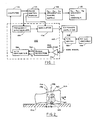
- FIGURE 1 is a block diagram of an NMR imaging system with respect to which the invention will be disclosed.
- the system generally designated 100, includes a pulse-control module 112 which provides properly timed pulse signals under the control of a host computer 114 to gradient magnetic field power supplies, collectively designated 116, used to energize gradient coils which form part of a gradient coil assembly generally indicated by a block 118.
- the assembly contains coils which, when energized, produce the G x , Gy, and G magnetic field gradients directed in the x-, y-, and z-axis directions, respectively, of the Cartesian coordinate system.
- the use of the G x p Gy, and G z gradients in imaging will be described hereinafter with reference to FIGS. 2 and 3.
- the pulse control module provides activating pulses to a radio frequency (RF) synthesizer 120 which is part of an RF transceiver system, portions of which are enclosed by dashed line block 122.
- the pulse control module also supplies modulating signals to a modulator 124 in the transceiver which modulates the output of the RF frequency synthesizer.
- the modulated RF signals are applied to an RF coil assembly 126 through an RF power amplifier 128 and a transmit/receive switch 130.
- the RF signals are used to excite nuclear spins in a sample object undergoing examination and which is positioned in the field of the RF coil.
- the NMR signals from the excited nuclear spins are received by the same or a different radio-frequency coil as was used to excite nuclear spins.
- the received signals are applied through the transmit/receivq switch to an RF preamplifier 152 and then to a quadrature phase detector 134 which provides in phase and quadrature outputs I and Q, respectively.
- the detected signals are digitized by A/D converter 136 and applied to computer 114 for processing in a well-known manner to, for example, reconstruct NMR images of the sample object.
- FIG. 2 depicts an NMR sample object 150, which in this case is a partially illustrated supine patient resting on a patient table 152.
- the patient typically is positioned in and longitudinally aligned with a polarizing magnetic field B directed in a positive Z-axis direction of the coordinate system.
- the origin of the coordinate system is typically taken to be the center of an imaging slice 154 having a thickness Z defined by dash lines 156 and 158.
- the thickness and the position of the slice which, in this case, is selected to be in the region of the upper-third torso of patient 150, is determined by the strength of the polarizing magnetic field B , the magnitude of the gradient magnetic fields used, and the frequency content used to modulate the RF excitation pulses, as is well known to those skilled in the art.
- FIG. 3 depicts a portion of what now can be referred to as a conventional imaging pulse sequence of the type known as two-dimensional Fourier transform (2DFT) and which is frequently also referred to as "spin warp."
- This pulse sequence is useful in obtaining, in a well-known manner, imaging data to reconstruct an image of, for example, imaging volume 154 depicted in FIG. 2.
- This pulse sequence is an improvement over conventional pulse sequences in that it utilizes phase-alternated RF excitation pulses which, as disclosed and claimed in U.S. Patent 4,443,760 (assigned to the same assignee as the present invention and incorporated herein by reference), produce phase-alternated NMR signals. When these signals are subtracted, those signal components having an inverted phase reinforce while undesired base-line error components whose phase was not reversed cancel.
- 2DFT two-dimensional Fourier transform
- FIG. 3 depicts four phase-encoding views 1, 1', 2, and 2'.
- Each of view pairs 1-1' and 2-2 ' utilize the same amplitude of the G y phase-encoding gradient which will be discussed hereinafter.
- the G y gradient can be selected to have, for example, 128, 256, or 512 different amplitudes.
- FIG. 3 there is shown an interval 1 (indicated along the horizontal axis), a selective 90° RF excitation pulse applied in the presence of a positive G magnetic field gradient pulse.
- Pulse control module 112 FIG.
- the excitation pulse can be amplitude modulated by a sin x/x function such that the excited imaging slice has a substantially rectangular profile.
- the frequency of the excitation pulse is dependent on the strength of the applied magnetic fields and the NMR species being imaged in accordance with the well-known Larmor equation.
- the pulse-control module also applies activating signals to the gradient power supply to generate, in this case, the G gradient pulse.
- G z , G y , and G x gradient pulses are applied simultaneously in interval 2.
- the G gradient in interval 2 is a rephasing pulse typically selected such that the time integral of the G z gradient waveform over interval 2 is approximately equal to a negative 1/2 of the time integral of the G z gradient waveform over interval 1.
- the function of this G z pulse is to rephase the nuclear spins excited in interval 1.
- the G y gradient pulse as alluded to hereinabove, is a phase-encoding pulse selected to have different amplitudes in each of views 1, 2, etc., to encode spatial phase information in the y-axis direction.
- the G x gradient pulse in interval 2 is a dephasing pulse needed to dephase the nuclear spins by a predetermined amount to delay the time of occurrence of a spin-echo signal S 1 (t) in interval 4.
- the spin echo is produced by the application of a typically, nonselective 180° RF pulse in interval 3.
- the 180° RF pulse is a time-reversal pulse which reverses the direction of spin dephasing.
- This in combination with the linear G magnetic field gradient pulse results in a spin-echo signal being produced in interval 4.
- This spin-echo signal is sampled in the presence of the linear G x gradient pulse to encode spatial information in the direction of the X axis.
- View 1' is substantially identical to view 1 with the exception that the 90° RF pulse applied in interval 5 is 180° out of phase relative to the 90° pulse in interval 1, as suggested by the negative sign.
- the S 2 (t) spin-echo signal in interval 8 is also phase alternated relative to spin-echo signal S 1 (t).
- the spurious FID signals due to imperfect 180° RF pulses preceding the spin-echo signals are not phase alternated.
- signal S 2 (t) is subtracted from signal S 1 (t)
- the spin-echo signals reinforce, while the undesired spurious FID signals, along with other error components, such as DC offset, cancel.
- the total scanning time is doubled.
- interval 6 the amplitude of the G y gradient is incremented to its next value and repeated in view 2', interval 16. This process is repeated until the G gradient is sequenced through its entire range of amplitudes.
- image information is obtained by applying a two-dimensional Fourier transform process to the collected data.
- Interval TR is termed the repetition time and is defined as the period of time between the beginning of a pulse sequence (one view) and the beginning of a succeeding, substantially identical, pulse sequence.
- judicious choice of the repetition time can be used to significantly reduce or eliminate breathing motion artifacts. It has been determined that these artifacts are caused by motion-induced phase and amplitude errors in the phase-encoding direction (Y axis in the case of the pulse sequence depicted in FIG. 3) when using the spin-warp imaging sequence.
- the artifacts due to such errors should be distinguished from image blurring (loss of resolution) due to simple displacement of pixel information fror. its true position in the image.
- the artifacts which are reduced or eliminated by the method of the invention are actual ghost images (artifacts) of the real (desired) image which are displaced in the phase-encoding direction.
- the displacement of the ghost images is due to the fact that the scan data, which represents the Fourier transform of the object, is distorted. In this case, phase errors actually represent a shift in pixel position in K-space and thereby account for the displacement.
- the solid line portions represent ghost displacement within the system field of view, bounded by dash lines 186 and 188 disposed on either side of center line 180.
- displacement lines would continue beyond the field-of-view lines, as suggested by the dash line extensions of lines 182-185.
- displacement lines 182-185 fold back into field of view as indicated by solid line segments 186-189, respectively.
- the determination of the breathing rate for the purpose of calculating optimum repetition times for eliminating or minimizing motion-induced artifacts may be accomplished by any suitable means such as conventional external respiration monitors.
- the NMR spectrometer instrument itself, is utilized for this purpose. Briefly, this is accomplished by acquiring NMR data in such a manner that the breathing motion induces amplitude modulation of the NMR signal. Breathing rate can then be determined by analysis of the modulated signals. The manner in which this is realized will now be described in greater detail with initial reference to FIGS. 2 and 3.
- the respiration rate can be determined by monitoring the integrated spin-echo magnitude spectrum as a function of time.
- Phase-alternated views (1', 2 !... etc.) are not counted toward the 64-view total, but are used to eliminate baseline errors, as discussed before.
- the 90° RF excitation pulses are modulated so as to excite an imaging slice 154 (FIG. 2) in the upper torso near, for example, the diaphragm, which is designated by reference numeral 160 in FIG. 2.
- the diaphragm (or other tissue mass), which normally lies outside the plane of the imaging slice, moves in and out of the volume of the slice, as suggested by the dash line depiction 162 of the diaphragn and bidirectional arrow 163.
- the intensity of the spin-echo signal originating from slice 154 changes with the breathing cycle due to the respiration-induced changes in the proton spin density and movement of material within the imaging slice being monitored.
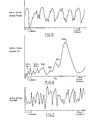
- FIGURE 5 depicts a plot of the complex spin-echo modulus (magnitude) of a data set acquired using a 64-view sequence described hereinabove integrated over the sampling interval over which the spin-echo signal is sampled.
- interval 4 (FIG. 3)
- the spin-echo signal is sampled a number of times equal to 128, 256, or 512.
- the magnitude of the spin echo is indicated along the vertical axis, while the horizontal axis corresponds to view number (1 to 64 in this case), or time with 2.56 sec./division.
- the repetition time TR of the pulse sequence was selected to be 200 msec., which, due to the use of phase-alternated pulses (views 1', 2',..., etc.) to eliminate baseline error components, results in a 400 msec. period between increments in the amplitude of the G phase-encoding gradient.
- the spin-echo magnitude has a cyclic character which has been found to be in accord with the respiratory cycle.
- the breathing period can be estimated by determining the average time between the magnitude peaks and recalling that there are 2.56 sec./division. In this manner, the breathing cycle is seen to be about 3.5 seconds.
- a more precise method for measuring the breathing period is to plot the Fourier transform of the spin-echo modulus with respect to view (or time) as a function of respiration period (instead of the customary frequency abcissa). Such a plot is depicted in FIG. 6, which corresponds to the data in FIG. 5.
- a peak 200 in the spectrum occurs at approximately 3.75 seconds and is taken to be the respiration period.
- a peak-finder computer program can be used to analyze the spectral data to find the peak with the highest amplitude at the lowest frequency, thereby to determine the breathing cycle.
- peaks such as those designated 201-207 represent the spectra of complicated patient motion. It has been found that too many such peaks with large amplitudes indicate considerable patient motion. Experience has also shown that under such conditions, useable images are usually difficult to obtain. The presence and severity of such motion has been monitored and used as an indicator of whether satisfactory images could be obtained. It will be apparent that such an indication can be advantageously obtained in preliminary studies of the breathing cycle, without actually performing imaging scans. This permits a more efficient use of scanner time.
- spin-echo modulus M i
- R(S i ) and I(S i ) designate real and imaginary parts of the complex spin echo.
- M i may be stated as where E i is the discrete spin-echo signal sample and N s is the nunber of samples taken in time T s .
- This form of the expression is particularly appropriate because the scan data actually comprises discrete samples of the NMR spin-echo signals.
- the graph such as that in FIG. 6 is then obtained by plotting F K as the ordinate and 1/K as the abcissa.
- phase of the complex spin echo integrated over the sample interval (8.192 sec.) could be used to determine the breathing period.
- a plot of phase versus view number is depicted in FIG. 7. It is seen that interpretation of the phase plot is not as easy as that of the magnitude, probably because the integral extended over the entire spin-echo time.
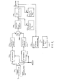
- the spin-echo modulus (M i ) and the Fourier transform of M i , (FK), are determined in computer 114, which is part of the NMR system described with reference to FIG. 1. It is, however, possible to utilize dedicated circuit devices to determine M i and F K . An exemplary system which could be used will be described next with reference to FIG. 8.
- Quadrature phase detector 134 coupled at its input to receive NMR signals from a preamplifier 132. Both the detector and preamplifier may be the same devices 134 and 132 as in the system of FIG. 1.
- Quadrature outputs I and Q are each applied to real time, analog integrator circuits 220 and 222.
- the integrators are reset (e.g., by a reset signal from pulse control module 112, FIG. 1) in anticipation of the integration operation for the next view.
- the outputs of the integrator circuits are squared in circuits 224 and 226, summed in a summer circuit 228. The square root of the resulting sum signal is taken by a square root circuit 230.
- the spin-echo modulus can be displayed on a monitor 232 coupled to square root circuit 230.
- the display which would be similar to that plot displayed in FIG. 5, could then be used to estimate the breathing perioa in the manner described hereinabove. It should be noted that elimination of the step of taking the square root of the signal would not materially alter the use of the plot for estimating the breathing period. The effect would be to alter the amplitude of the peaks displayed in FIG. 5, but not the temporal positions thereof.
- the output of square root circuit 230 is digitized in A/D converter 234, and applied to digital display 236, FFT unit 238, and, optionally, to computer 114.
- the plot displayed on display 236 is similar to that depicted in FIG. 5 and can be used for the same purpose.
- the digitized signals are sampled and stored in FFT unit 238 which calculates F K , the Fourier transform, of the spin-echo modulus in accordance with Equation (3).
- a display 240 coupled to the FFT unit is used to display F K as the ordinate and 1/K as the abcissa, in the manner described hereinabove with reference to FIG. 6. It should be noted that computer 114 could be used, instead of separate FFT unit 238, to perform the transform operation.
Landscapes
- Health & Medical Sciences (AREA)
- Life Sciences & Earth Sciences (AREA)
- Engineering & Computer Science (AREA)
- Physics & Mathematics (AREA)
- Signal Processing (AREA)
- General Health & Medical Sciences (AREA)
- Biophysics (AREA)
- Physiology (AREA)
- Pulmonology (AREA)
- Public Health (AREA)
- Veterinary Medicine (AREA)
- Pathology (AREA)
- Biomedical Technology (AREA)
- Heart & Thoracic Surgery (AREA)
- Medical Informatics (AREA)
- Molecular Biology (AREA)
- Surgery (AREA)
- Animal Behavior & Ethology (AREA)
- Artificial Intelligence (AREA)
- Psychiatry (AREA)
- Computer Vision & Pattern Recognition (AREA)
- Mathematical Physics (AREA)
- Cardiology (AREA)
- Power Engineering (AREA)
- Nuclear Medicine, Radiotherapy & Molecular Imaging (AREA)
- Radiology & Medical Imaging (AREA)
- High Energy & Nuclear Physics (AREA)
- Condensed Matter Physics & Semiconductors (AREA)
- General Physics & Mathematics (AREA)
- Magnetic Resonance Imaging Apparatus (AREA)
Applications Claiming Priority (2)
| Application Number | Priority Date | Filing Date | Title |
|---|---|---|---|
| US06/673,688 US4564017A (en) | 1984-11-21 | 1984-11-21 | Method and apparatus for respiration monitoring with an NMR scanner |
| US673688 | 1984-11-21 |
Publications (2)
| Publication Number | Publication Date |
|---|---|
| EP0182265A2 true EP0182265A2 (fr) | 1986-05-28 |
| EP0182265A3 EP0182265A3 (fr) | 1987-06-10 |
Family
ID=24703705
Family Applications (1)
| Application Number | Title | Priority Date | Filing Date |
|---|---|---|---|
| EP85114390A Withdrawn EP0182265A3 (fr) | 1984-11-21 | 1985-11-12 | Procédé et appareil pour le contrôle de la respiration avec un appareil à balayage de résonance magnétique nucléaire |
Country Status (4)
| Country | Link |
|---|---|
| US (1) | US4564017A (fr) |
| EP (1) | EP0182265A3 (fr) |
| JP (1) | JPS61143035A (fr) |
| IL (1) | IL76805A0 (fr) |
Cited By (2)
| Publication number | Priority date | Publication date | Assignee | Title |
|---|---|---|---|---|
| EP0255220A3 (fr) * | 1986-06-27 | 1988-11-30 | Picker International, Inc. | Imagerie pour résonance magnétique |
| US4961426A (en) * | 1988-08-19 | 1990-10-09 | Siemens Medical Systems, Inc. | Method for retrospectively gating NMR data |
Families Citing this family (30)
| Publication number | Priority date | Publication date | Assignee | Title |
|---|---|---|---|---|
| GB8417290D0 (en) * | 1984-07-06 | 1984-08-08 | Picker Int Ltd | Nuclear magnetic resonance method |
| DE3570135D1 (en) * | 1984-08-01 | 1989-06-15 | Siemens Ag | Apparatus for producing images of an object under examination |
| DE3430625A1 (de) * | 1984-08-20 | 1986-02-27 | Siemens AG, 1000 Berlin und 8000 München | Einrichtung fuer die kernspin-tomographie |
| US4616183A (en) * | 1984-10-22 | 1986-10-07 | General Electric Company | Method for reducing baseline error components in NMR signals |
| US4724386A (en) * | 1985-09-30 | 1988-02-09 | Picker International, Inc. | Centrally ordered phase encoding |
| US4694837A (en) * | 1985-08-09 | 1987-09-22 | Picker International, Inc. | Cardiac and respiratory gated magnetic resonance imaging |
| GB2190502B (en) * | 1986-05-16 | 1989-12-13 | Gen Electric Plc | Nuclear magnetic resonance methods and apparatus |
| JPS63164943A (ja) * | 1986-09-03 | 1988-07-08 | 株式会社日立製作所 | Nmrイメ−ジング方式 |
| US4855910A (en) * | 1986-10-22 | 1989-08-08 | North American Philips Corporation | Time-clustered cardio-respiratory encoder and method for clustering cardio-respiratory signals |
| JP2644744B2 (ja) * | 1987-02-04 | 1997-08-25 | 株式会社日立製作所 | Nmrスペクトロスコピックイメージング装置 |
| JPS63200745A (ja) * | 1987-02-16 | 1988-08-19 | 株式会社東芝 | 磁気共鳴イメ−ジング装置 |
| IL82184A (en) * | 1987-04-10 | 1990-07-26 | Elscint Ltd | Reducing respiratory motion artifacts in nuclear magnetic resonance images |
| US4777438A (en) * | 1987-04-27 | 1988-10-11 | Picker International, Inc. | Multiple imaging with improved signal-to-noise ratio |
| JPH064066B2 (ja) * | 1987-10-15 | 1994-01-19 | 株式会社東芝 | 磁気共鳴イメージング装置 |
| US5035244A (en) * | 1988-02-23 | 1991-07-30 | Elscint Ltd. | Motion artifact minimization |
| US4984574A (en) * | 1988-11-23 | 1991-01-15 | Seth Goldberg | Noninvasive fetal oxygen monitor using NMR |
| US4982161A (en) * | 1989-08-24 | 1991-01-01 | North American Philips Corporation | Multimode magnetic resonance fast imaging method |
| US4994743A (en) * | 1989-10-27 | 1991-02-19 | General Electric Company | Method for monitoring respiration with acquired NMR data |
| JPH0492644A (ja) * | 1990-08-07 | 1992-03-25 | Hitachi Ltd | 磁気共鳴検査装置 |
| US5251128A (en) * | 1990-11-19 | 1993-10-05 | General Electric Company | Motion artifact reduction in projection imaging |
| US5122747A (en) * | 1990-11-21 | 1992-06-16 | Mayo Foundation For Medical Education And Research | Spiral three-dimensional fourier transform NMR scan |
| WO1992019264A1 (fr) * | 1991-05-01 | 1992-11-12 | University Of New Mexico | Biomodulateurs utilises comme agents de contraste universels |
| JP3146033B2 (ja) * | 1991-11-05 | 2001-03-12 | 株式会社東芝 | 磁気共鳴イメージング装置 |
| US5339035A (en) * | 1993-05-07 | 1994-08-16 | General Electric Company | MR imaging with rectangular magnetization transfer pulse |
| US5363844A (en) * | 1993-08-13 | 1994-11-15 | Mayo Foundation For Medical Education And Research | Breath-hold monitor for MR imaging |
| JPH07163537A (ja) * | 1994-09-01 | 1995-06-27 | Hitachi Ltd | Nmrイメージング方法 |
| JP3639825B2 (ja) * | 2002-04-03 | 2005-04-20 | キヤノン株式会社 | 動画像表示方法、プログラム、コンピュータ可読記憶媒体、及び動画像表示装置 |
| US7714575B2 (en) * | 2003-10-15 | 2010-05-11 | General Electric Company | Method and apparatus for enhanced magnetic preparation in MR imaging |
| US7693569B1 (en) | 2004-10-12 | 2010-04-06 | General Electric Company | Method and system of determining motion in a region-of-interest directly and independently of k-space trajectory |
| US12385998B2 (en) * | 2023-10-31 | 2025-08-12 | GE Precision Healthcare LLC | System and method for reduced fine-line artifacts in magnetic resonance imaging |
Family Cites Families (9)
| Publication number | Priority date | Publication date | Assignee | Title |
|---|---|---|---|---|
| US23950A (en) * | 1859-05-10 | 1859-05-10 | Clock-dial | |
| USRE23950E (en) | 1946-12-23 | 1955-02-22 | Method and means for chemical analysis | |
| BE543241A (fr) * | 1954-12-06 | |||
| US2955252A (en) * | 1959-04-16 | 1960-10-04 | Exxon Research Engineering Co | Combination analyzer-sampler |
| CS155245B2 (fr) * | 1969-07-18 | 1974-05-30 | ||
| US4516075A (en) * | 1983-01-04 | 1985-05-07 | Wisconsin Alumni Research Foundation | NMR scanner with motion zeugmatography |
| JPS59155239A (ja) * | 1983-02-23 | 1984-09-04 | 株式会社東芝 | 診断用核磁気共鳴装置 |
| JPS6120541A (ja) * | 1984-07-05 | 1986-01-29 | 株式会社島津製作所 | 呼吸性体動による核磁気共鳴像の歪を補正する方法 |
| JPS6173643A (ja) * | 1984-09-19 | 1986-04-15 | 株式会社 日立メデイコ | デ−タ収集方法 |
-
1984
- 1984-11-21 US US06/673,688 patent/US4564017A/en not_active Expired - Fee Related
-
1985
- 1985-10-24 IL IL76805A patent/IL76805A0/xx unknown
- 1985-11-12 EP EP85114390A patent/EP0182265A3/fr not_active Withdrawn
- 1985-11-20 JP JP60258826A patent/JPS61143035A/ja active Pending
Non-Patent Citations (1)
| Title |
|---|
| ELECTRO, May 1984, pages 1-10, Conference, New York, US; Z.J.J. STEKLY: "Nuclear magnetic resonance imaging" * |
Cited By (2)
| Publication number | Priority date | Publication date | Assignee | Title |
|---|---|---|---|---|
| EP0255220A3 (fr) * | 1986-06-27 | 1988-11-30 | Picker International, Inc. | Imagerie pour résonance magnétique |
| US4961426A (en) * | 1988-08-19 | 1990-10-09 | Siemens Medical Systems, Inc. | Method for retrospectively gating NMR data |
Also Published As
| Publication number | Publication date |
|---|---|
| EP0182265A3 (fr) | 1987-06-10 |
| US4564017A (en) | 1986-01-14 |
| IL76805A0 (en) | 1986-02-28 |
| JPS61143035A (ja) | 1986-06-30 |
Similar Documents
| Publication | Publication Date | Title |
|---|---|---|
| US4567893A (en) | Method of eliminating breathing artifacts in NMR imaging | |
| US4564017A (en) | Method and apparatus for respiration monitoring with an NMR scanner | |
| US4614195A (en) | Method for reduction of motion artifacts in Fourier transform NMR imaging techniques | |
| Jezzard et al. | Characterization of and correction for eddy current artifacts in echo planar diffusion imaging | |
| JP2974759B2 (ja) | Nmr画像における動きアーチファクトの低減装置および方法 | |
| Wan et al. | Reduction of geometric and intensity distortions in echo‐planar imaging using a multireference scan | |
| EP0218838A2 (fr) | Procédé et dispositif pour réduire des artéfacts des images à cause des variations du signal périodique dans la tomographie à résonance magnétique nucléaire | |
| Song et al. | In vivo micro‐imaging using alternating navigator echoes with applications to cancellous bone structural analysis | |
| US20120268121A1 (en) | Method for r*2 quantification with magnetic resonance imaging | |
| US4751462A (en) | Method for acquiring NMR data which is subject to periodic variations | |
| DE102011006230A1 (de) | Verfahren zur Korrektur einer Phaseninformation in MR-Bildern und entsprechende Magnetresonanzanlage | |
| CN107024670A (zh) | 磁共振系统的校正方法及装置 | |
| DE19750637A1 (de) | Verfahren zur Messung und Kompensation von durch Wirbelströme induzierten sich örtlich und zeitlich ändernden Magnetfeldern | |
| Hedley et al. | Motion artifact suppression: a review of post-processing techniques | |
| EP0383631A2 (fr) | Système d'imagerie par résonance magnétique | |
| EP0182267B1 (fr) | Procédé pour supprimer les effets des composants d'erreur de la ligne de base en vue des applications d'imagerie RMN | |
| US4616183A (en) | Method for reducing baseline error components in NMR signals | |
| US4994743A (en) | Method for monitoring respiration with acquired NMR data | |
| US5200700A (en) | Reduction of NMR artifacts caused by time varying linear geometric distortion | |
| DE10057628A1 (de) | Kompensation von Schwankungen im Polarisationsmagnetfeld während der Magnetresonanzabbildung | |
| CA2326416C (fr) | Recuperation de la perte du signal due aux non-homogeneites de champ en imagerie par echographie plane par resonance magnetique | |
| US4994744A (en) | Method for combining acquired NMR data to suppress motion artifacts | |
| US6239598B1 (en) | Process for rapid sample trajectory calibration for magnetic resonance imaging | |
| DE19747563A9 (de) | Lageerfassungsvorrichtung | |
| US9915713B2 (en) | Determining positions of a magnetic field probe in a magnetic resonance measurement |
Legal Events
| Date | Code | Title | Description |
|---|---|---|---|
| PUAI | Public reference made under article 153(3) epc to a published international application that has entered the european phase |
Free format text: ORIGINAL CODE: 0009012 |
|
| AK | Designated contracting states |
Kind code of ref document: A2 Designated state(s): CH DE FR GB IT LI NL SE |
|
| PUAL | Search report despatched |
Free format text: ORIGINAL CODE: 0009013 |
|
| AK | Designated contracting states |
Kind code of ref document: A3 Designated state(s): CH DE FR GB IT LI NL SE |
|
| 17P | Request for examination filed |
Effective date: 19871114 |
|
| STAA | Information on the status of an ep patent application or granted ep patent |
Free format text: STATUS: THE APPLICATION HAS BEEN WITHDRAWN |
|
| 17Q | First examination report despatched |
Effective date: 19880126 |
|
| 18W | Application withdrawn |
Withdrawal date: 19880302 |
|
| RIN1 | Information on inventor provided before grant (corrected) |
Inventor name: GLOVER, GARY HAROLD |