EP0182270A2 - Dispositif pour la production de plaques d'impression par électrophotographie - Google Patents
Dispositif pour la production de plaques d'impression par électrophotographie Download PDFInfo
- Publication number
- EP0182270A2 EP0182270A2 EP85114402A EP85114402A EP0182270A2 EP 0182270 A2 EP0182270 A2 EP 0182270A2 EP 85114402 A EP85114402 A EP 85114402A EP 85114402 A EP85114402 A EP 85114402A EP 0182270 A2 EP0182270 A2 EP 0182270A2
- Authority
- EP
- European Patent Office
- Prior art keywords
- plate
- flaps
- rows
- air nozzles
- exposure
- Prior art date
- Legal status (The legal status is an assumption and is not a legal conclusion. Google has not performed a legal analysis and makes no representation as to the accuracy of the status listed.)
- Withdrawn
Links
- 238000007639 printing Methods 0.000 claims abstract description 62
- 230000007246 mechanism Effects 0.000 claims description 9
- 239000002184 metal Substances 0.000 claims description 9
- 238000013016 damping Methods 0.000 claims description 8
- 238000004519 manufacturing process Methods 0.000 claims description 3
- 125000006850 spacer group Chemical group 0.000 claims description 3
- 238000007667 floating Methods 0.000 abstract description 3
- 230000032258 transport Effects 0.000 description 41
- 230000009191 jumping Effects 0.000 description 6
- 238000000034 method Methods 0.000 description 4
- 230000006835 compression Effects 0.000 description 2
- 238000007906 compression Methods 0.000 description 2
- 230000008878 coupling Effects 0.000 description 2
- 238000010168 coupling process Methods 0.000 description 2
- 238000005859 coupling reaction Methods 0.000 description 2
- 238000000151 deposition Methods 0.000 description 2
- 229910000831 Steel Inorganic materials 0.000 description 1
- 239000011248 coating agent Substances 0.000 description 1
- 238000000576 coating method Methods 0.000 description 1
- 230000007423 decrease Effects 0.000 description 1
- 239000011888 foil Substances 0.000 description 1
- 238000003384 imaging method Methods 0.000 description 1
- 239000000463 material Substances 0.000 description 1
- 238000007665 sagging Methods 0.000 description 1
- 239000000523 sample Substances 0.000 description 1
- 239000010959 steel Substances 0.000 description 1
Images


Classifications
-
- G—PHYSICS
- G03—PHOTOGRAPHY; CINEMATOGRAPHY; ANALOGOUS TECHNIQUES USING WAVES OTHER THAN OPTICAL WAVES; ELECTROGRAPHY; HOLOGRAPHY
- G03G—ELECTROGRAPHY; ELECTROPHOTOGRAPHY; MAGNETOGRAPHY
- G03G15/00—Apparatus for electrographic processes using a charge pattern
- G03G15/65—Apparatus which relate to the handling of copy material
- G03G15/6529—Transporting
-
- B—PERFORMING OPERATIONS; TRANSPORTING
- B65—CONVEYING; PACKING; STORING; HANDLING THIN OR FILAMENTARY MATERIAL
- B65H—HANDLING THIN OR FILAMENTARY MATERIAL, e.g. SHEETS, WEBS, CABLES
- B65H3/00—Separating articles from piles
- B65H3/08—Separating articles from piles using pneumatic force
- B65H3/0808—Suction grippers
- B65H3/0816—Suction grippers separating from the top of pile
-
- B—PERFORMING OPERATIONS; TRANSPORTING
- B65—CONVEYING; PACKING; STORING; HANDLING THIN OR FILAMENTARY MATERIAL
- B65H—HANDLING THIN OR FILAMENTARY MATERIAL, e.g. SHEETS, WEBS, CABLES
- B65H5/00—Feeding articles separated from piles; Feeding articles to machines
- B65H5/22—Feeding articles separated from piles; Feeding articles to machines by air-blast or suction device
- B65H5/222—Feeding articles separated from piles; Feeding articles to machines by air-blast or suction device by suction devices
-
- G—PHYSICS
- G03—PHOTOGRAPHY; CINEMATOGRAPHY; ANALOGOUS TECHNIQUES USING WAVES OTHER THAN OPTICAL WAVES; ELECTROGRAPHY; HOLOGRAPHY
- G03G—ELECTROGRAPHY; ELECTROPHOTOGRAPHY; MAGNETOGRAPHY
- G03G15/00—Apparatus for electrographic processes using a charge pattern
- G03G15/65—Apparatus which relate to the handling of copy material
- G03G15/6597—Apparatus which relate to the handling of copy material the imaging being conformed directly on the copy material, e.g. using photosensitive copy material, dielectric copy material for electrostatic printing
-
- B—PERFORMING OPERATIONS; TRANSPORTING
- B65—CONVEYING; PACKING; STORING; HANDLING THIN OR FILAMENTARY MATERIAL
- B65H—HANDLING THIN OR FILAMENTARY MATERIAL, e.g. SHEETS, WEBS, CABLES
- B65H2701/00—Handled material; Storage means
- B65H2701/10—Handled articles or webs
- B65H2701/19—Specific article or web
- B65H2701/1928—Printing plate
-
- G—PHYSICS
- G03—PHOTOGRAPHY; CINEMATOGRAPHY; ANALOGOUS TECHNIQUES USING WAVES OTHER THAN OPTICAL WAVES; ELECTROGRAPHY; HOLOGRAPHY
- G03G—ELECTROGRAPHY; ELECTROPHOTOGRAPHY; MAGNETOGRAPHY
- G03G2215/00—Apparatus for electrophotographic processes
- G03G2215/00362—Apparatus for electrophotographic processes relating to the copy medium handling
- G03G2215/00367—The feeding path segment where particular handling of the copy medium occurs, segments being adjacent and non-overlapping. Each segment is identified by the most downstream point in the segment, so that for instance the segment labelled "Fixing device" is referring to the path between the "Transfer device" and the "Fixing device"
- G03G2215/00371—General use over the entire feeding path
-
- G—PHYSICS
- G03—PHOTOGRAPHY; CINEMATOGRAPHY; ANALOGOUS TECHNIQUES USING WAVES OTHER THAN OPTICAL WAVES; ELECTROGRAPHY; HOLOGRAPHY
- G03G—ELECTROGRAPHY; ELECTROPHOTOGRAPHY; MAGNETOGRAPHY
- G03G2215/00—Apparatus for electrophotographic processes
- G03G2215/00362—Apparatus for electrophotographic processes relating to the copy medium handling
- G03G2215/00367—The feeding path segment where particular handling of the copy medium occurs, segments being adjacent and non-overlapping. Each segment is identified by the most downstream point in the segment, so that for instance the segment labelled "Fixing device" is referring to the path between the "Transfer device" and the "Fixing device"
- G03G2215/00396—Pick-up device
-
- G—PHYSICS
- G03—PHOTOGRAPHY; CINEMATOGRAPHY; ANALOGOUS TECHNIQUES USING WAVES OTHER THAN OPTICAL WAVES; ELECTROGRAPHY; HOLOGRAPHY
- G03G—ELECTROGRAPHY; ELECTROPHOTOGRAPHY; MAGNETOGRAPHY
- G03G2215/00—Apparatus for electrophotographic processes
- G03G2215/00362—Apparatus for electrophotographic processes relating to the copy medium handling
- G03G2215/00443—Copy medium
- G03G2215/00518—Recording medium, e.g. photosensitive
-
- G—PHYSICS
- G03—PHOTOGRAPHY; CINEMATOGRAPHY; ANALOGOUS TECHNIQUES USING WAVES OTHER THAN OPTICAL WAVES; ELECTROGRAPHY; HOLOGRAPHY
- G03G—ELECTROGRAPHY; ELECTROPHOTOGRAPHY; MAGNETOGRAPHY
- G03G2215/00—Apparatus for electrophotographic processes
- G03G2215/00362—Apparatus for electrophotographic processes relating to the copy medium handling
- G03G2215/00443—Copy medium
- G03G2215/00523—Other special types, e.g. tabbed
Definitions
- the invention relates to a device for the electrophotographic production of printing forms which are stacked in the undelected state in a magazine and are individually removed from the magazine by means of suction elements and transported to a charging station in order to be moved from there to further processing stations of the device.
- the magazine is inclined to the vertical, the lifting cylinder in its receiving position being directed perpendicularly onto the uncoated side of the uppermost printing form and the bowl-shaped plate running parallel to the uncoated side of the printing form and onto this for lifting off the top plate is lowered from the stack until the suction elements sit on the printing form.
- DE-PS 24 62 216 describes a device for the electrophotographic production of printing forms in which the individual printing form is lifted from a stack in a plate magazine by a transport device which consists of a transport carriage with a vacuum suction device and which forms the printing form to an exposure stage transported.
- the transport carriage runs over two guide rails and can be driven by a motor which is arranged on the upper side and which engages via a gearwheel with a rack and pinion drive which is arranged parallel to the direction of movement of the transport carriage.
- the transport trolley has a vacuum plate on the underside, which is connected to a vacuum pump via a number of holes.
- the printing plate is sucked onto the vacuum plate by negative pressure and then the transport carriage is moved in the direction of the exposure stage.
- the exposure platform is lowered and the printing plate is lowered onto the exposure platform by releasing the vacuum in the vacuum plate of the transport carriage.
- the exposure stage comprises a vacuum plate, which is subjected to negative pressure in order to suck up the pressure plate.
- a device is known with which a printing plate lowered in a circular arc from above onto a support surface, the photoconductively coated side of which is directed upwards, is transferred to a device equipped with rollers for further transport, without the printing plate coming to rest on the rollers during lowering and without the photoconductive device Layer of the pressure plate comes into contact with the rollers.
- a swiveling lifting cylinder takes the printing form in the form of a printing plate from a magazine and places the printing plate in a circular arc with the front part on a suction plate of the exposure table.
- a row of transport and drive rollers is arranged parallel to the two side edges of the printing plate in the transport direction, the transport rollers lying first in the transport direction of the printing plate being pivotable outwards from the rows in order to place the front part of the printing plate on the suction plate of the exposure table without jamming to enable.
- the two parallel roller strips with the transport and drive rollers lie against the side edges of the printing plate and center them during the exposure. Since the rollers have a certain groove depth, they protrude on the edge or on the side edges of the pressure plate inside by this groove depth, so that exposure of the pressure plate to the edge is not possible.
- the known feed and transport devices work mechanically and comprise either a transport carriage which moves the individual printing plate from processing station to processing station and holds the printing plate by vacuum, or driven transport rollers which are in contact with the side edges of the printing plate in order to transport them further.
- These devices work satisfactorily, but are mechanically complex and their transport capacity is limited to about 60 plates per minute.
- a higher plate throughput can hardly be achieved because, due to the inertia of the mechanical parts of the transport device, their starting and stopping for picking up from a table of a processing station and the transfer of a single printing plate from processing station to processing station do not allow a higher working frequency.
- the object of the invention is to improve a device of the type described above so that it enables a higher transport speed for printing forms without impairing transport safety.
- This object is achieved in that the individual printing form in the form of a printing plate is guided with the aid of compressed air at a distance from the surfaces of tables of the processing stations from one processing station to the next processing station and that at least two rows of air nozzles are arranged in the tables, that run obliquely inside the tables and are pressurized with compressed air.
- the two rows of air nozzles in the surface of each table are aligned parallel to the transport direction of the pressure plate or parallel to the narrow sides of the tables, and there are also two further rows of air nozzles in the table of the development station, which are perpendicular to the two Rows of air jets run.
- the oblique air nozzles are spatially arranged in such a way that the projections of the air nozzles of the two rows in the basic plane parallel to the table surface include angles between 40 ° and 50 ° with the transport direction of the printing plate, and that these projections at this angle onto the associated narrow sides of the individual table are directed.
- the projections of the air nozzles of the two rows close in on the long sides of the individual NEN table parallel plane an angle between 40 0 and 50 0 with the vertical direction of the transport direction of the printing plate.
- the table of the charging station and the table of the development station are equipped with pivotable flaps which are arranged along the narrow sides of the individual table in such a way that the distance d between the longitudinal edges raised flaps and the associated narrow side is three to six millimeters.
- the table of the exposure station does not have swiveling flaps, but instead has fixed guide plates along the narrow sides of the table. With the narrow sides of the exposure station, these guide plates enclose air ducts which are 3 to 6 mm wide and 5 to 10 mm deep.
- the distance between the two rows of air nozzles is 35-50% of the distance between the raised flaps or the fixed guide plates.
- the table of the development station is equipped with swiveling flaps on the long sides.
- Tables of the exposure and development stations each have an adjustable brake which comprises two pressure cylinders which are articulated on bearing blocks of an angled fastening strut for the brake.
- the fastening strut is attached to a spacer which is connected to the underside of the respective table.
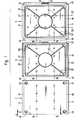
- a charging table 2 an exposure table 8 and a development table 9 of the charging, exposure or development station are shown.
- a printing form in the form of a printing plate is transported in the transport direction A from one processing station to the next processing station, as will be described in more detail later.
- pivotable flaps 5, 5 are attached, which are shown in FIG. 1 in a horizontally pivoted position, in which they lie in the plane of the charging table 2.
- two rows of air nozzles 18, 18 are arranged, which run obliquely within the tables and can be acted upon by compressed air.
- the compressed air creates an air cushion underneath the pressure plate, at a distance to the surfaces of the tables 2, 8, 9 the printing plate is suspended from one processing station to the next processing station.
- a jumping suction device 61 is arranged in the table near each corner of the charging table 2, the upper side of the piston of which, depending on the position of the piston, is either flush with the surface of the charging table 2 or lies slightly below the surface. With the suction cups 61, the pressure plate is sucked in, held and lifted off the charging table 2 as soon as it is to be transported from the charging station to the exposure station.
- the exposure table 8 is equipped with fixed guide plates 21, 22 on its narrow sides 46 and 47. In the middle of the longitudinal edge 49 of the exposure table 8 lying at the rear in the transport direction A there is an adjustable brake 6, which will be described in more detail below. In the surface of the exposure table 8 there is a network of interconnected vacuum channels 62 which are connected to a vacuum device, not shown, which generates a corresponding negative pressure for sucking and holding a printing plate on the exposure table 8.
- the development table 9 is equipped with pivotable flaps 24, 24 along its narrow sides 46, 47, which are arranged along the longitudinal sides 48, 49 of the development table 9.
- the surface of the development table 9 there are two further rows of air nozzles 23, 23 which run at right angles to the two rows of air nozzles 18, 18.
- the air nozzles 23, 23 enable the developed printing plate to be transported further at a right angle to the transport direction A.
- a system of vacuum channels 62 which is largely identical to the network of vacuum channels of the exposure table 8.
- the center of the rear longitudinal side 49 of the development table 9 is opposite another adjustable brake 6.
- the flap 24 located on this longitudinal side 49 has a recess 51 for the brake 6.
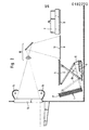
- the mode of operation of the device is explained on the basis of the schematic partial view shown in FIG. 2.
- a plate magazine 1 which is arranged inclined to the horizontal, there is a stack of pressure plates 17.
- the top edge of the stack or the top pressure plate 17 of the stack is always kept at the same level by means of a drive device, not shown.
- the inside of the plate magazine 1 facing photoconductive coating of the individual printing plate 17 is covered by a film or a sheet of paper, which when removing the Printing plate 17 is removed from the plate magazine 1.
- the support table 2 is brought into the position shown in broken lines by a swivel mechanism.
- This swivel mechanism consists of a cylinder 3, the piston rod of which is connected to one end of a coupling strut 10 which can be pivoted about a fixed point and is articulated at the other end to the underside of the charging table 2.
- Another coupling strut 11 is articulated at a fixed point 12 on the one hand and on the underside of the charging table on the other. If the piston rod of the cylinder 3 is retracted, the charging table 2, as already mentioned, is brought into the position shown in broken lines, in which the suction cups 61 grip the uppermost pressure plate in the plate magazine 1 and tighten it on the table surface. Then the piston rod of the cylinder 3 is extended so that the charging table 2 is pivoted into the horizontal charging position.
- the pressure plate 17 is still sucked onto the surface of the charging table 2 by means of the suction cups 61.
- the flaps 5, 5 are pivoted along the narrow sides 46, 47 of the charging table 2 into the plane of the charging table 2, so that a corona 4 can move a short distance from the pressure plate 17 without obstruction over the full length of the pressure plate 17 to charge the photoconductive layer of the pressure plate 17 to the required voltage.
- the flaps 5, 5 are placed upright, ie perpendicular to the surface of the charging table 2, and the vacuum of the suction cups 61 is released, so that when the air nozzles 18, 18 are pressurized with compressed or transport air, the resulting air cushion lifts the pressure plate 17 from the surface of the charging table 2 and transports it in the direction of the exposure table 8.
- the brake 6 (see FIG. 1), which is arranged on the one long side 49 of the exposure table 8, stops the movement of the printing plate 17.
- the printing plate 17 is guided and aligned by the stationary guide plates 21 and 22 of the exposure table 8, the The distance between these guide plates is approximately 1 mm greater than the length of the pressure plate 17.
- the transport or compressed air of the air nozzles 18, 18 of the exposure table 8 is switched off, the brake 6 is pivoted into a position lower than the surface of the exposure table 8, and the vacuum channels 62 of the exposure table 8 are subjected to negative pressure, so that the pressure plate 17 is sucked in.
- the printing plate 17 is then exposed by means of a template, not shown, which is inserted into a template holder 13 known per se.
- the light sources 14 and 15 form the original via an imaging optics 16 onto the printing plate 17 lying on the exposure table 8.
- the exposure time is controlled in accordance with the desired residual charging voltage, which is measured by means of a suitable probe, not shown, and as soon as the residual charging voltage is reached, the exposure is ended.
- the vacuum in the system of vacuum Channels 62 of the exposure table 8 is broken down, the transport or compressed air of the air nozzles 18, 18 of the exposure table 8 and the development table 9 is switched on, so that the printing plate 17 can be transported in the direction of the development table 9 while floating.
- the flaps 5.5 along the narrow sides 46 and 47 of the development table 9 are simultaneously pivoted upright.
- the further brake 6, which is arranged on the one long side 49 of the development table 9 at the point at which the pivotable flap 24 has the recess 51 (see FIG. 1), stops the pressure plate 17 in its end position.
- the transport or compressed air of the air nozzles 18, 18 is switched off and a vacuum is built up in the system of the vacuum channels 62, as a result of which the pressure plate is sucked onto the surface of the development table 9.
- a developing device 7, which contains dry toner, is moved over the exposed printing plate 17 and the latent image is developed by the dry toner.
- the vacuum in the vacuum channels 62 is released, the flaps 24, 24 are folded up on the long sides of the exposure table 9 and the transport or compressed air for the air nozzles 23, 23 is switched on.
- the two rows of air nozzles 23, 23 run at right angles to the rows of air nozzles 18, 18, so that the pressure plate 17 is transported out of the device in the direction of the starting position of the developing device 7.
- the flaps 24, 24 are folded down and the development device 7 is returned to its starting position. Another, already loaded and exposed printing plate is positioned on the development table 9 and the development process is started.
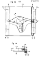
- FIG. 3 shows the transfer of a printing plate from the charging table 2 to the exposure table 8.
- the charging table 2 is shown broken away in the area of the two rows of air nozzles 18, 18, projections of the air nozzles 18, 18 in two mutually perpendicular planes for the sake of better clarity not being shown flat but only by lines.
- the projections 18 ', 18 "of the air nozzles 18, 18 of the two rows into the base plane of the table parallel to the table surface form an angle between 40 and 50 °, preferably 45 °, with the transport direction A of the pressure plate 17.
- These projections 18', 18 ′′ are directed at the associated narrow sides 46, 47 of the charging table 2 at this angle ⁇ .
- the same spatial arrangement also exists for the air nozzles 18, 18 of the exposure and development table 8 or 9.
- the distance d between the flaps 5.5 raised longitudinally and the associated narrow side 46 or 47 of the charging table 2 is 3 to 6 mm.
- the flaps 5.5 consist, for example, of structural sheets with a thickness of 1 mm.
- These air ducts between the flaps 5, 5 folded up and the narrow sides 46, 47 of the charging table 2 on the one hand and the guide plates 21, 22 and the narrow sides 46, 47 of the exposure table 8 on the other hand ensure that there is space below the edges of the pressure plate 17, can flow into the excess transport air and that moreover a stronger air cushion is formed than under the remaining surface of the pressure plate 17, so that sagging of the edges of the pressure plate 17 is prevented downwards.
- the distance between the two rows of air nozzles 18, 18 from one another is approximately 35 to 50% of the distance between the raised flaps 5.5 or between the fixed guide plates 21, 22, in particular the row distance is 40% of the distance between the flaps or the guide plates.
- the two rows of air nozzles 18, 18 are arranged symmetrically to the center line of each table in the transport direction A. For example, within a row of air nozzles 18 The distance between two adjacent air nozzles is 25 mm, the first and the last air nozzle 18 of a row being 50 mm away from the long sides. Although this is not shown, a strip of sheet metal or foil material can bridge the gap between two tables between the individual tables.
- FIGS. 4a and 4b An adjustment mechanism for the flaps 5, 5, which is identical to the adjustment mechanism for the flaps 24, 24, is shown schematically in detail in FIGS. 4a and 4b.
- the adjustment mechanism for the flaps 5, 5 of the charging table 2 is located in a plan view below the table 2.
- the two adjustment mechanisms for the flaps 5, 5 and 24, 24 of the development table 9 are attached below the same.
- the adjustment mechanism consists of a swivel plate 52, a pressure cylinder 53 acting on the swivel plate and two cables 54, 55 connecting the flaps to the swivel plate, which can be sheathed steel wires, for example.
- the ropes 54, 55 engage at one end at two diametrically opposite points near the circumference of the swivel plate 52, while their other ends are fastened in offset bores 56, 57 by metal blocks 58, 58.
- the bore 56 has a smaller diameter than the bore 57, in which the individual cable 54 or 55, which has a ball at its end, is introduced.
- the ball has a larger diameter than the bore 56, so that pulling out the cable in the direction of the swivel plate 52 from the offset bores is not possible.
- each metal block is mounted a flap 58.58 5 or 24, wherein the metal block about a pivot point 59 which is spaced from the respective cable 54 and 55, respectively, can be pivoted through an angle up to 90 0th
- the pressure cylinder 53 is fastened with its piston rod near the circumference of the swivel plate 52 at a point which lies on the bisector H of the fastening points for the cables 54, 55 on the swivel plate 52.
- 4a shows the extended position of the piston rod of the pressure cylinder 53, in which the flaps 5, 5 or 24, 24 are placed upright and form a right angle with the surface of the respective table.
- the swivel plate 52 executes a clockwise rotation, in which the cables 54 and 55 are pulled outwards, since the metal blocks 58, 58 pivot outwards about the pivot points 59, 59 and with them connected flaps 5,5 and 24,24 can be folded into the plane of the surface of the respective table.
- a stop 60 for example a screw, is attached, which limits the pivoting movement of the metal blocks 58, 58 when the flaps are pivoted upright.
- the pivot points 59, 59 are in themselves designed as stub axles, which are surrounded by leg springs, not shown are that ensure an elastic mounting of the individual flaps.
- FIG. 5 shows a partial perspective view of a flap 24 which is arranged parallel to the longitudinal side 49 of the development table 9.
- the flap 24 is shown in the folded-down state with solid lines, while the flap 24 which is placed upright is indicated by dashed lines.
- the distance d between the long side 49 and the flap 24 placed upright is 3 to 6 mm.
- the brake 6 shown schematically in FIG. 6 comprises two pressure cylinders 37 and 39 which are articulated on bearing blocks 36 and 40 of an angled fastening strut 35 of the brake.
- the fastening strut 35 is fastened to a spacer 44 which extends downwards from the underside of the exposure and development tables 8 and 9, respectively.
- the piston rod 34 of the one pressure cylinder 37 is connected to the other pressure cylinder 39 via an angled connecting piece 38, the connecting piece 38 being fastened directly to the housing of the printing cylinder 39.
- the damping element 42 brakes the one floating on the air cushion Pressure plate 17, springs back slightly and then pushes the pressure plate into the desired position, in which the transport air of the air nozzles is switched off and the vacuum in the vacuum channels in the surface of the table 8 or 9 is switched on, around the pressure plate 17 to the surface suck in.
- the two pressure cylinders 37 and 39 or their piston rods 34 and 41 are retracted.
- To initiate the braking process first the piston rod 34 of the pressure cylinder 37 is extended and then the piston rod 41 of the pressure cylinder 39 in order to bring the elastic damping element 42 into its braking position.
- the pivoting of the damping element 42 takes place in the reverse order, ie first the piston rod 41 of the pressure cylinder 39 retracts and then the piston rod 34 of the pressure cylinder 37.
- a recess 43 is formed below the table surface at the point at which the brake 6 is arranged a recessed cut-out is provided in the long side of the table in question, which enables the piston rod 41 of the pressure cylinder 39 to be extended without hindrance to a position in which the damping element 42 brakes the pressure plate 17 and can position it above the table.
- a cylindrical vacuum housing 27 of the suction cup 61 on the underside of the charging table 2 encloses a displaceable piston 29, the piston crown 28 of which rests against the bottom and the inner wall of the vacuum housing 27 and seals a vacuum chamber 32 which is located between the piston 29 and the cylindrical inner wall of the vacuum housing 27 extends.
- the vacuum chamber 32 is connected via a vacuum line 25 to a vacuum device, not shown.
- the piston 29 widens upwards to a frustoconical piston head 63, which projects into an open bore 30 of the charging table 2.
- a sleeve-like rubber seal 33 is inserted, the upper edge of which is in alignment with the table surface in the rest position of the suction cup 61.
- a compression spring 45 surrounds the piston 29 and is supported against the top of the piston head 28 on the one hand and against the inside of a top surface 65 of the vacuum housing 27 on the other hand.
- the stepped piston crown 28 there is a compensating bore 26 which connects the vacuum chamber 32 to a continuous bore 66 of the piston 29 which runs in the axial direction.
- the piston 29 moves upward in the vacuum housing 27, since the piston head 28 seals against the cylindrical inner wall and the bottom of the vacuum housing 27.
- This upward movement of the piston arises from the fact that there is atmospheric pressure in the bore 66, while there is a negative pressure in the vacuum chamber 32 and, because of the small diameter of the compensating bore 26, pressure compensation cannot initially occur between the bore 66 and the vacuum chamber 32.
- the atmospheric pressure in the bore 66 acts on the underside of the piston crown 28 with atmospheric pressure and thus pushes the piston 29 upward, since outside the piston 29 there is less pressure in the vacuum chamber 32 than in the bore 66.
- the pressure cylinders of the device are preferably operated with compressed air, but the use of hydraulic pressure cylinders is also possible.
Landscapes
- Engineering & Computer Science (AREA)
- Mechanical Engineering (AREA)
- Physics & Mathematics (AREA)
- General Physics & Mathematics (AREA)
- Exposure And Positioning Against Photoresist Photosensitive Materials (AREA)
- Sheets, Magazines, And Separation Thereof (AREA)
Applications Claiming Priority (2)
| Application Number | Priority Date | Filing Date | Title |
|---|---|---|---|
| DE19843442755 DE3442755A1 (de) | 1984-11-23 | 1984-11-23 | Vorrichtung zur elektrofotografischen herstellung von druckformen |
| DE3442755 | 1984-11-23 |
Publications (1)
| Publication Number | Publication Date |
|---|---|
| EP0182270A2 true EP0182270A2 (fr) | 1986-05-28 |
Family
ID=6250988
Family Applications (1)
| Application Number | Title | Priority Date | Filing Date |
|---|---|---|---|
| EP85114402A Withdrawn EP0182270A2 (fr) | 1984-11-23 | 1985-11-13 | Dispositif pour la production de plaques d'impression par électrophotographie |
Country Status (5)
| Country | Link |
|---|---|
| US (1) | US4660959A (fr) |
| EP (1) | EP0182270A2 (fr) |
| JP (1) | JPS61132963A (fr) |
| AU (1) | AU5022385A (fr) |
| DE (1) | DE3442755A1 (fr) |
Families Citing this family (4)
| Publication number | Priority date | Publication date | Assignee | Title |
|---|---|---|---|---|
| DE4129022A1 (de) * | 1991-08-31 | 1993-03-11 | Heidelberger Druckmasch Ag | Magazin fuer den automatischen druckplattenwechsel |
| US6113346A (en) | 1996-07-31 | 2000-09-05 | Agfa Corporation | Method for loading and unloading a supply of plates in an automated plate handler |
| US6390306B1 (en) * | 1998-12-31 | 2002-05-21 | Agfa Corporation Law & Patent Department | Printing plate storage and transportation system |
| EP1772262B1 (fr) * | 2005-10-04 | 2009-05-27 | Punch Graphix International N.V. | Système d'exposition et méthode pour le chargement de plaques d'impression |
Family Cites Families (7)
| Publication number | Priority date | Publication date | Assignee | Title |
|---|---|---|---|---|
| US3617127A (en) * | 1969-02-20 | 1971-11-02 | Mobil Oil Corp | Photographic material transport with vacuum platen |
| DE2452979C2 (de) * | 1974-11-08 | 1981-12-24 | Hoechst Ag, 6000 Frankfurt | Beleuchtungseinrichtung in einem Projektionskopiergerät |
| US4226526A (en) * | 1976-10-04 | 1980-10-07 | Harry Arthur Hele Spence-Bate | Transport and positioning mechanism |
| DE3012815A1 (de) * | 1980-04-02 | 1981-10-08 | Hoechst Ag, 6000 Frankfurt | Vorrichtung fuer den transport von druckformen |
| DE3012761A1 (de) * | 1980-04-02 | 1981-10-08 | Hoechst Ag, 6000 Frankfurt | Vorrichtung fuer den einzug und den transport von druckformen |
| US4371309A (en) * | 1981-02-25 | 1983-02-01 | Principe William L | Air table |
| DE3122321A1 (de) * | 1981-06-05 | 1982-12-23 | Hoechst Ag, 6000 Frankfurt | Einzugs- und transportvorrichtung fuer druckformen |
-
1984
- 1984-11-23 DE DE19843442755 patent/DE3442755A1/de not_active Withdrawn
-
1985
- 1985-11-13 EP EP85114402A patent/EP0182270A2/fr not_active Withdrawn
- 1985-11-14 US US06/798,118 patent/US4660959A/en not_active Expired - Fee Related
- 1985-11-19 AU AU50223/85A patent/AU5022385A/en not_active Abandoned
- 1985-11-25 JP JP60262731A patent/JPS61132963A/ja active Pending
Also Published As
| Publication number | Publication date |
|---|---|
| DE3442755A1 (de) | 1986-05-28 |
| US4660959A (en) | 1987-04-28 |
| AU5022385A (en) | 1986-05-29 |
| JPS61132963A (ja) | 1986-06-20 |
Similar Documents
| Publication | Publication Date | Title |
|---|---|---|
| EP0037064B1 (fr) | Dispositif pour le transport de plaques d'impression | |
| EP0043508B1 (fr) | Dispositif pour le transport et l'alignement de plaques d'impression | |
| DE19839924A1 (de) | Vorrichtung zur Abnahme von Folien von einem Folienstapel in einer Stapelstation und zur Ablage der abgenommenen Folien in einer Zusammenlegestation | |
| DE69104116T2 (de) | Verfahren und Vorrichtung zum automatischen Bedrucken von vier Seiten eines schachtelförmigen Gegenstands. | |
| EP0361179A2 (fr) | Dispositif de positionnement pour le transfert précis de pièces entre un chariot de transport et une installation fixe | |
| EP0037065B1 (fr) | Dispositif pour faire entrer et transporter des plaques d'impression | |
| EP0066789B1 (fr) | Dispositif pour le transport pour clichés | |
| DE69402653T2 (de) | Verfahren zum Austauschen von Stanzwerkzeugen in einer Plattenpresse sowie Vorrichtung zur Durchführung des Verfahrens | |
| EP0046474A1 (fr) | Procédé et dispositif pour imprimer des objets en forme de caisse avec des pochoirs disposés verticalement | |
| DE4109174C2 (de) | Verfahren und Vorrichtung zum einzelnen Transportieren von Offsetdruckplatten | |
| EP0182270A2 (fr) | Dispositif pour la production de plaques d'impression par électrophotographie | |
| EP0071171B1 (fr) | Dispositif suceur | |
| DE2824088C2 (de) | Druckplattenherstellungsgerät | |
| DE2819530C3 (de) | Vorrichtung zum Aufkleben von Schutztaschen auf Blätter | |
| DE8528934U1 (de) | Repetier-Kopiermaschine | |
| DE19903358C1 (de) | Verfahren und Vorrichtung zur Montage eines Möbel-Korpus | |
| DE2029810A1 (de) | Vorrichtung zur Handhabung von Gegen standen | |
| DE3346128C2 (fr) | ||
| DE3914866C2 (de) | Vorrichtung zum Einbringen, Verpressen und Ausbringen eines Schichtpaketes in eine Heißpresse | |
| DE19839923C2 (de) | Vorrichtung zur Abnahme von Folien von einem Folienstapel in einer Stapelstation und zur Ablage der abgenommenen Folien in einer Zusammenlegestation | |
| EP0084077B1 (fr) | Dispositif pour transporter automatiquement des plaques supports circuits imprimés à des installations d'étendage au rouleau | |
| DE3105415A1 (de) | Vorrichtung fuer den transport von steifem plattenfoermigem druckgut | |
| DE3206056A1 (de) | Vorrichtung zur herstellung von druckplatten | |
| DE3207903A1 (de) | Anlage zum belichten von fotopolymeren materialien | |
| DE8221306U1 (de) | Vorrichtung mit beweglichem Tisch zur Herstellung von Schichtglas |
Legal Events
| Date | Code | Title | Description |
|---|---|---|---|
| PUAI | Public reference made under article 153(3) epc to a published international application that has entered the european phase |
Free format text: ORIGINAL CODE: 0009012 |
|
| AK | Designated contracting states |
Kind code of ref document: A2 Designated state(s): BE DE FR GB IT NL |
|
| STAA | Information on the status of an ep patent application or granted ep patent |
Free format text: STATUS: THE APPLICATION HAS BEEN WITHDRAWN |
|
| 18W | Application withdrawn |
Withdrawal date: 19871124 |
|
| RIN1 | Information on inventor provided before grant (corrected) |
Inventor name: SCHOEN, KLAUS-PETER |