EP0182310A1 - Dispositif rayonnant de la lumière - Google Patents
Dispositif rayonnant de la lumière Download PDFInfo
- Publication number
- EP0182310A1 EP0182310A1 EP85114543A EP85114543A EP0182310A1 EP 0182310 A1 EP0182310 A1 EP 0182310A1 EP 85114543 A EP85114543 A EP 85114543A EP 85114543 A EP85114543 A EP 85114543A EP 0182310 A1 EP0182310 A1 EP 0182310A1
- Authority
- EP
- European Patent Office
- Prior art keywords
- cylinder
- light
- light rays
- optical
- radiator
- Prior art date
- Legal status (The legal status is an assumption and is not a legal conclusion. Google has not performed a legal analysis and makes no representation as to the accuracy of the status listed.)
- Granted
Links
- 230000003287 optical effect Effects 0.000 claims abstract description 56
- 239000004020 conductor Substances 0.000 claims abstract description 21
- XLYOFNOQVPJJNP-UHFFFAOYSA-N water Substances O XLYOFNOQVPJJNP-UHFFFAOYSA-N 0.000 claims abstract description 12
- 239000007788 liquid Substances 0.000 claims abstract description 9
- 230000005540 biological transmission Effects 0.000 description 3
- 238000010276 construction Methods 0.000 description 2
- 230000007423 decrease Effects 0.000 description 2
- 238000001514 detection method Methods 0.000 description 2
- 238000005286 illumination Methods 0.000 description 2
- 230000029553 photosynthesis Effects 0.000 description 2
- 238000010672 photosynthesis Methods 0.000 description 2
- 239000000126 substance Substances 0.000 description 2
- 238000006243 chemical reaction Methods 0.000 description 1
- 230000003247 decreasing effect Effects 0.000 description 1
- 230000007547 defect Effects 0.000 description 1
- 230000001939 inductive effect Effects 0.000 description 1
- 230000005855 radiation Effects 0.000 description 1
Images
Classifications
-
- A—HUMAN NECESSITIES
- A01—AGRICULTURE; FORESTRY; ANIMAL HUSBANDRY; HUNTING; TRAPPING; FISHING
- A01G—HORTICULTURE; CULTIVATION OF VEGETABLES, FLOWERS, RICE, FRUIT, VINES, HOPS OR SEAWEED; FORESTRY; WATERING
- A01G7/00—Botany in general
- A01G7/04—Electric or magnetic or acoustic treatment of plants for promoting growth
- A01G7/045—Electric or magnetic or acoustic treatment of plants for promoting growth with electric lighting
-
- F—MECHANICAL ENGINEERING; LIGHTING; HEATING; WEAPONS; BLASTING
- F21—LIGHTING
- F21S—NON-PORTABLE LIGHTING DEVICES; SYSTEMS THEREOF; VEHICLE LIGHTING DEVICES SPECIALLY ADAPTED FOR VEHICLE EXTERIORS
- F21S10/00—Lighting devices or systems producing a varying lighting effect
- F21S10/002—Lighting devices or systems producing a varying lighting effect using liquids, e.g. water
-
- G—PHYSICS
- G02—OPTICS
- G02B—OPTICAL ELEMENTS, SYSTEMS OR APPARATUS
- G02B6/00—Light guides; Structural details of arrangements comprising light guides and other optical elements, e.g. couplings
- G02B6/10—Light guides; Structural details of arrangements comprising light guides and other optical elements, e.g. couplings of the optical waveguide type
- G02B6/14—Mode converters
-
- A—HUMAN NECESSITIES
- A01—AGRICULTURE; FORESTRY; ANIMAL HUSBANDRY; HUNTING; TRAPPING; FISHING
- A01G—HORTICULTURE; CULTIVATION OF VEGETABLES, FLOWERS, RICE, FRUIT, VINES, HOPS OR SEAWEED; FORESTRY; WATERING
- A01G9/00—Cultivation in receptacles, forcing-frames or greenhouses; Edging for beds, lawn or the like
- A01G9/24—Devices or systems for heating, ventilating, regulating temperature, illuminating, or watering, in greenhouses, forcing-frames, or the like
- A01G9/249—Lighting means
-
- F—MECHANICAL ENGINEERING; LIGHTING; HEATING; WEAPONS; BLASTING
- F21—LIGHTING
- F21S—NON-PORTABLE LIGHTING DEVICES; SYSTEMS THEREOF; VEHICLE LIGHTING DEVICES SPECIALLY ADAPTED FOR VEHICLE EXTERIORS
- F21S10/00—Lighting devices or systems producing a varying lighting effect
- F21S10/005—Lighting devices or systems producing a varying lighting effect using light guides
-
- G—PHYSICS
- G02—OPTICS
- G02B—OPTICAL ELEMENTS, SYSTEMS OR APPARATUS
- G02B6/00—Light guides; Structural details of arrangements comprising light guides and other optical elements, e.g. couplings
- G02B6/0001—Light guides; Structural details of arrangements comprising light guides and other optical elements, e.g. couplings specially adapted for lighting devices or systems
- G02B6/0096—Light guides; Structural details of arrangements comprising light guides and other optical elements, e.g. couplings specially adapted for lighting devices or systems the lights guides being of the hollow type
-
- Y—GENERAL TAGGING OF NEW TECHNOLOGICAL DEVELOPMENTS; GENERAL TAGGING OF CROSS-SECTIONAL TECHNOLOGIES SPANNING OVER SEVERAL SECTIONS OF THE IPC; TECHNICAL SUBJECTS COVERED BY FORMER USPC CROSS-REFERENCE ART COLLECTIONS [XRACs] AND DIGESTS
- Y02—TECHNOLOGIES OR APPLICATIONS FOR MITIGATION OR ADAPTATION AGAINST CLIMATE CHANGE
- Y02P—CLIMATE CHANGE MITIGATION TECHNOLOGIES IN THE PRODUCTION OR PROCESSING OF GOODS
- Y02P60/00—Technologies relating to agriculture, livestock or agroalimentary industries
- Y02P60/14—Measures for saving energy, e.g. in green houses
Definitions
- the present invention relates to a light radiator for effectively diffusing and radiating light rays which have been transmitted through an optical cable or the like to the outside of the optical conductor cable.
- the present applicant has previously proposed various ways to focus solar rays or artificial light rays by the use of lenses or the like and to guide the same into an optical conductor cable thereby transmitting them onto an optional desired place through the optical conductor cable.
- Solar rays or artificial light rays transmitted and emitted in such a way are employed for inducing photo-synthesis and for use in illuminating or for other like purposes, as for example, to better promote the cultivation of plants.
- the light rays transmitted through the optical conductor cable have directional characteristics. Supposing that the end portion of the optical conductor cable is cut off and that the light rays are emitted therefrom, the radiation angle for the focused light rays is, in general, equal to approximately 46°. That is quite a narrow field.
- the present applicant has already proposed various kinds of light radiators capable of effectively diffusing light rays which have been transmitted through an optical conductor cable and for radiating the same, as illumination, over a desired area.
- Fig. 1 is a cross-sectional view for explaining an embodiment of a light radiator previously proposed by the present applicant.
- 10 is a transparent cylinder
- 20 is an optical conductor
- 30 is an optical means
- 40 is a liquid pump.
- a light-emitting end 20a of the optical conductor 20 is provided at one end portion of the cylinder 10.
- the light rays transmitted through the optical conductor 20 are emitted into the cylinder 10 from the light-emitting end 20a of the optical conductor 20 and transmitted in the cylinder 10 toward the other end portion thereof by being reflected on the inner wall surface and the outer wall surface of the cylinder 10.
- the cylinder 10 is filled with an optical oil 50 and a transparent cylindrical optical means 30 is slidably installed therein.
- One end surface 30a of the optical means 30, that is, a surface located at the side for receiving the light rays is formed in a state of a plane not inclined while the other end surface thereof is formed in a state of an inclined plane 30b.
- An air chamber 36 is built up by use of a cover member 35 at the outside of the inclined surface 30b.
- the light rays L guided into the cylinder 10 enter the optical means 30 through the plane 30a thereof, and then the light rays L are reflected on the inclined plane 30b at the opposite side thereof and emitted outside of the cylinder 10. Plants are cultivated outside of the cylinder 10.
- the light rays, emitted from the cylinder 10 in such a manner as mentioned heretofore, are supplied to the plants as a photo-synthesis reaction light source for the plants.
- the open end of a pipe 41 is located at one end potion of the cylinder 10 and that of another pipe 42 is located at the other end portion of the cylinder 10, and differential pressure is applied between both ends of the optical means 30 by use of the pipes 41 and 42.
- the optical means 30 can be moved inside of the cylinder 10 by the action of the differential pressure. The light rays can thereby be supplied over a wide area.
- 61 and 62 are photo-sensors mounted on the outer circumferential surface of the cylinder 10 at the side where the light rays reflected by use of the optical means 30 pass through.
- the photo-sensor 61 detects that the optical means 30 has arrived at one end of the cylinder 10 and the detection signal generated by the photo-sensor 61 controls the liquid pump 40 so as to create the differential pressure needed to move the optical means 30 toward another end of the cylinder 10.
- the photo-sensor 62 detects that the optical means 30 has arrived at another end of the cylinder 10 and the detection signal generated by the photo-sensor 62 controls the liquid pump 40 so as to create the differential pressure needed to move the optical means 30 toward the above-mentioned end of the cylinder 10 at this time.
- the photo-sensors 61 and 62 are constructed in such a way that the sensors can be mounted on and removed from the cylinder 10 or the sensors can be moved along the cylinder 10. Therefore, it would be possible to optionally set the movement area of the optical means 30 and thereby to effectively supply the light rays, transmitted through the optical conductor 20, to the plants.
- the optical oil 50 which is very expensive, is employed to fill the cylinder 10 as a way of moving the optical means 30 inside of the cylinder 10 and as a medium for transmitting the light rays therein.
- the light rays guided into the cylinder tend to leak to the rear side of the optical means through the side wall of the cylinder or by passing through the optical means portion. Consequently the utilization efficiency is not always sufficient.
- the cylinder is linear, the light rays can only be distributed in a linear fashion along the axis of the light radiator. Therefore, the light rays cannot always be distributed sufficiently for illuminating a desired area.
- the present invention was created in consideration of the actual circumstances as mentioned above.
- the aims of the present invention is to decrease the cost of its construction by employing transparent water instead of the afore-mentioned optical oil and further to improve its utilization efficiency by having the plural light radiators connected in cascade.
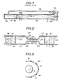
- Fig. 2 is a cross-sectional view for explaining an embodiment of a light radiator according to the present invention.
- the same reference numeral as that of Fig. 1 is attached to the part performing the same action as that of Fig. 1.
- transparent water 7 is enclosed in the transparent cylinder 10.
- the light rays L emitted into the cylinder 10 from the optical conductor are transmitted in transparent water and arrive at the optical means 30 as in the case of the light radiator shown in Fig. 1.
- the light rays are reflected on the inclined surface of the optical means 30 and discharged outside of the cylinder 10.
- the end portion of the cylinder 10 is formed in the state of a narrow tube 10b with a tapered portion 10a. The end portion thereof can be connected with the other light radiator 10' through the tube portion 10a.
- 80 is a transparent connecting tube for connecting the cylinder 10 with the other cylinder 10'. The light rays L guided into the cylinder 10 are reflected on the optical means 30 as mentioned above and discharged outside of the cylinder 10.
- a part of the light rays passes through the wall of the cylinder 10 as shown by an arrow La or leaks from the optical means 30 as shown by an arrow Lb. Such a part of the light rays may become loss component thereof. In the light radiator shown in Fig. 2, the light rays leaking in such a way can also be utilized effectively.
- the light rays La passing through the wall of the cylinder 10 are radiated into the next- stage cylinder 10' at the inclined portion 10a' of the following light radiator 10', and the light rays Lb passing through the narrow tube portion 10b are also radiated into the cylinder 10'.
- the same optical means 30' as mentioned before is enclosed in the cylinder 10', the light rays L' radiated into the cylinder 10', in such a manner as mentioned above, are discharged outside of the cylinder 10' by the use of the optical means 30'.
- the value of N'A increases so that the light rays are apt to leak outside therefrom. Consequently, it is necessary to employ a substance of high transparency as the tube 80 and to make the external side portion thereof air-clad. And then, in order to effectively guide the light rays entering the tube 80 into the following light radiator 10', the rear end 80' of the tube 80 is preferably elongated in the direction of the inclined front end portion 10a' of the following light radiator 10'.
- the narrow tube portion 10b of the light radiator 10 is brought into close contact with the narrow tube portion lOb' of the following light radiator 10' as shown in Fig. 2, the light rays passing through the wall of the narrow tube portion 10b are effectively transmitted to the following narrow tube portion lOb'.
- those narrow tube portions are filled with optical paste, water or the like, the loss of transmission is not so large even though the narrow tube portions are separated from each other.
- a large number of light radiators can be preferably connected in cascade so as to combine those light radiators in a desired form as shown in Fig. 3.
- Fig. 3 is a view showing a state of connecting plural light radiators in cascade as mentioned above.
- a light radiator having a desired shape as a whole, by combining a plurality of light radiators.
- the light rays can be radiated from the outside toward the area A.
- the plants are cultivated on the area A, it will be possible to effectively supply light rays to the plants.
- the amount of the light rays decreases at the following lower stage thereof as a matter of course.
- the end surface of the optical conductor 20' is brought into close contact with the inclined surface 10' thereof so as to let the light rays enter the light radiator through the inclined surface. In such a manner, the light rays can be almost uniformly emitted from all of the light radiators.
- the present invention since transparent water is employed as a light rays transmission medium and as a means for moving the optical means, the cost of the light radiator can be decreased.
- the present invention has the merit to effectively utilize the light rays guided into the cylinder by connecting the plural light radiators in cascade.
Landscapes
- Physics & Mathematics (AREA)
- Engineering & Computer Science (AREA)
- General Engineering & Computer Science (AREA)
- General Physics & Mathematics (AREA)
- Optics & Photonics (AREA)
- Life Sciences & Earth Sciences (AREA)
- Environmental Sciences (AREA)
- Biodiversity & Conservation Biology (AREA)
- Botany (AREA)
- Ecology (AREA)
- Forests & Forestry (AREA)
- Light Guides In General And Applications Therefor (AREA)
- Non-Portable Lighting Devices Or Systems Thereof (AREA)
- Planar Illumination Modules (AREA)
Applications Claiming Priority (2)
| Application Number | Priority Date | Filing Date | Title |
|---|---|---|---|
| JP59241410A JPS61120104A (ja) | 1984-11-15 | 1984-11-15 | 光ラジエ−タ |
| JP241410/84 | 1984-11-15 |
Publications (2)
| Publication Number | Publication Date |
|---|---|
| EP0182310A1 true EP0182310A1 (fr) | 1986-05-28 |
| EP0182310B1 EP0182310B1 (fr) | 1989-06-28 |
Family
ID=17073872
Family Applications (1)
| Application Number | Title | Priority Date | Filing Date |
|---|---|---|---|
| EP85114543A Expired EP0182310B1 (fr) | 1984-11-15 | 1985-11-15 | Dispositif rayonnant de la lumière |
Country Status (7)
| Country | Link |
|---|---|
| US (1) | US4703995A (fr) |
| EP (1) | EP0182310B1 (fr) |
| JP (1) | JPS61120104A (fr) |
| KR (1) | KR860004324A (fr) |
| AU (1) | AU581033B2 (fr) |
| CA (1) | CA1239131A (fr) |
| DE (1) | DE3571270D1 (fr) |
Families Citing this family (5)
| Publication number | Priority date | Publication date | Assignee | Title |
|---|---|---|---|---|
| AU581227B2 (en) * | 1984-06-07 | 1989-02-16 | Kei Mori | Light radiator |
| JPS61167905A (ja) * | 1985-01-21 | 1986-07-29 | Takashi Mori | 光ラジエ−タ |
| JPS62175702A (ja) * | 1986-01-29 | 1987-08-01 | Takashi Mori | 光ラジエ−タ |
| JPS6430415A (en) * | 1987-07-24 | 1989-02-01 | Takashi Mori | Cable inserting sash |
| FR2705435B1 (fr) * | 1993-05-14 | 1995-07-21 | Ermax | Agencement de source d'éclairage à fibre optique et à faisceau lumineux orientable. |
Citations (3)
| Publication number | Priority date | Publication date | Assignee | Title |
|---|---|---|---|---|
| FR47621E (fr) * | 1936-08-14 | 1937-06-15 | Cie Parisienne De Distrib D El | Luminaire combiné avec effet liquide |
| AT331552B (de) * | 1975-01-20 | 1976-08-25 | Ruthner Othmar | Verfahren und vorrichtung zur lichzufuhrung in hydroponischen pflanzenkulturen |
| EP0115843A2 (fr) * | 1983-02-04 | 1984-08-15 | Kei Mori | Appareil pour la distribution de la lumière à temps partagé |
Family Cites Families (5)
| Publication number | Priority date | Publication date | Assignee | Title |
|---|---|---|---|---|
| US3510195A (en) * | 1966-06-30 | 1970-05-05 | Gen Electric | Immersed fiber optics structure |
| US3514192A (en) * | 1967-04-11 | 1970-05-26 | Dynasciences Corp | Achromatic variable-angle fluid prism |
| AU581227B2 (en) * | 1984-06-07 | 1989-02-16 | Kei Mori | Light radiator |
| JPS613104A (ja) * | 1984-06-15 | 1986-01-09 | Takashi Mori | 光ラジエ−タ |
| JPS6167004A (ja) * | 1984-09-07 | 1986-04-07 | Takashi Mori | 光ラジエ−タ |
-
1984
- 1984-11-15 JP JP59241410A patent/JPS61120104A/ja active Pending
-
1985
- 1985-10-18 US US06/788,987 patent/US4703995A/en not_active Expired - Fee Related
- 1985-10-23 CA CA000493620A patent/CA1239131A/fr not_active Expired
- 1985-10-24 AU AU49031/85A patent/AU581033B2/en not_active Ceased
- 1985-11-15 KR KR1019850008555A patent/KR860004324A/ko not_active Withdrawn
- 1985-11-15 EP EP85114543A patent/EP0182310B1/fr not_active Expired
- 1985-11-15 DE DE8585114543T patent/DE3571270D1/de not_active Expired
Patent Citations (3)
| Publication number | Priority date | Publication date | Assignee | Title |
|---|---|---|---|---|
| FR47621E (fr) * | 1936-08-14 | 1937-06-15 | Cie Parisienne De Distrib D El | Luminaire combiné avec effet liquide |
| AT331552B (de) * | 1975-01-20 | 1976-08-25 | Ruthner Othmar | Verfahren und vorrichtung zur lichzufuhrung in hydroponischen pflanzenkulturen |
| EP0115843A2 (fr) * | 1983-02-04 | 1984-08-15 | Kei Mori | Appareil pour la distribution de la lumière à temps partagé |
Also Published As
| Publication number | Publication date |
|---|---|
| KR860004324A (ko) | 1986-06-20 |
| AU4903185A (en) | 1986-05-22 |
| US4703995A (en) | 1987-11-03 |
| AU581033B2 (en) | 1989-02-09 |
| DE3571270D1 (en) | 1989-08-03 |
| JPS61120104A (ja) | 1986-06-07 |
| CA1239131A (fr) | 1988-07-12 |
| EP0182310B1 (fr) | 1989-06-28 |
Similar Documents
| Publication | Publication Date | Title |
|---|---|---|
| US4740048A (en) | Light radiator | |
| US4822123A (en) | Optical radiator | |
| EP0058884B1 (fr) | Dispositif pour disperser la lumière sortant d'un guide lumineux | |
| JPH0249574A (ja) | 光ラジエータ | |
| EP0166339B1 (fr) | Dispositif rayonnant la lumière | |
| US4703995A (en) | Light radiator for diffusing and radiating light rays | |
| JPS59133507A (ja) | 人工光源装置 | |
| KR830008473A (ko) | 집어등 | |
| AU597010B2 (en) | A light radiator | |
| US4984862A (en) | Light radiator for the cultivation of fish | |
| EP0174031B1 (fr) | Dispositif rayonnant la lumière | |
| KR850001377B1 (ko) | 광 라디에이터 | |
| EP0189177A2 (fr) | Dispositif rayonnant de la lumière | |
| US4844598A (en) | Light focusing lens with centrally disposed light intercepting member | |
| US4702546A (en) | Light source device | |
| KR850001193B1 (ko) | 광 라디 에이터 | |
| KR900002583Y1 (ko) | 광 라디에이터 | |
| KR890005223B1 (ko) | 광라디에이터 | |
| JPS6057041B2 (ja) | 光ラジエ−タ | |
| KR880000118B1 (ko) | 광라디 에이티터 | |
| KR870000898Y1 (ko) | 집어등 | |
| JPS6180114A (ja) | 人工光源装置 | |
| KR880003491Y1 (ko) | 광라디 에이터 | |
| JPS5929205A (ja) | 光ラジエ−タ | |
| JPH02303416A (ja) | 光供給装置 |
Legal Events
| Date | Code | Title | Description |
|---|---|---|---|
| PUAI | Public reference made under article 153(3) epc to a published international application that has entered the european phase |
Free format text: ORIGINAL CODE: 0009012 |
|
| AK | Designated contracting states |
Kind code of ref document: A1 Designated state(s): CH DE FR GB IT LI NL SE |
|
| 17P | Request for examination filed |
Effective date: 19861127 |
|
| 17Q | First examination report despatched |
Effective date: 19871221 |
|
| GRAA | (expected) grant |
Free format text: ORIGINAL CODE: 0009210 |
|
| AK | Designated contracting states |
Kind code of ref document: B1 Designated state(s): CH DE FR GB IT LI NL SE |
|
| REF | Corresponds to: |
Ref document number: 3571270 Country of ref document: DE Date of ref document: 19890803 |
|
| ITF | It: translation for a ep patent filed | ||
| ET | Fr: translation filed | ||
| PGFP | Annual fee paid to national office [announced via postgrant information from national office to epo] |
Ref country code: FR Payment date: 19891107 Year of fee payment: 5 |
|
| PGFP | Annual fee paid to national office [announced via postgrant information from national office to epo] |
Ref country code: SE Payment date: 19891116 Year of fee payment: 5 |
|
| ITTA | It: last paid annual fee | ||
| PGFP | Annual fee paid to national office [announced via postgrant information from national office to epo] |
Ref country code: NL Payment date: 19891130 Year of fee payment: 5 Ref country code: GB Payment date: 19891130 Year of fee payment: 5 |
|
| PGFP | Annual fee paid to national office [announced via postgrant information from national office to epo] |
Ref country code: CH Payment date: 19891212 Year of fee payment: 5 |
|
| PGFP | Annual fee paid to national office [announced via postgrant information from national office to epo] |
Ref country code: DE Payment date: 19891229 Year of fee payment: 5 |
|
| PLBE | No opposition filed within time limit |
Free format text: ORIGINAL CODE: 0009261 |
|
| STAA | Information on the status of an ep patent application or granted ep patent |
Free format text: STATUS: NO OPPOSITION FILED WITHIN TIME LIMIT |
|
| 26N | No opposition filed | ||
| PG25 | Lapsed in a contracting state [announced via postgrant information from national office to epo] |
Ref country code: GB Effective date: 19901115 |
|
| PG25 | Lapsed in a contracting state [announced via postgrant information from national office to epo] |
Ref country code: SE Effective date: 19901116 |
|
| PG25 | Lapsed in a contracting state [announced via postgrant information from national office to epo] |
Ref country code: LI Effective date: 19901130 Ref country code: CH Effective date: 19901130 |
|
| PG25 | Lapsed in a contracting state [announced via postgrant information from national office to epo] |
Ref country code: NL Effective date: 19910601 |
|
| GBPC | Gb: european patent ceased through non-payment of renewal fee | ||
| NLV4 | Nl: lapsed or anulled due to non-payment of the annual fee | ||
| PG25 | Lapsed in a contracting state [announced via postgrant information from national office to epo] |
Ref country code: FR Effective date: 19910731 |
|
| REG | Reference to a national code |
Ref country code: CH Ref legal event code: PL |
|
| PG25 | Lapsed in a contracting state [announced via postgrant information from national office to epo] |
Ref country code: DE Effective date: 19910801 |
|
| REG | Reference to a national code |
Ref country code: FR Ref legal event code: ST |
|
| EUG | Se: european patent has lapsed |
Ref document number: 85114543.3 Effective date: 19910705 |