EP0182334A2 - Caméra de vidéo à haute vitesse et procédé de prise de vues à haute vitesse utilisant un fractionneur de rayons - Google Patents
Caméra de vidéo à haute vitesse et procédé de prise de vues à haute vitesse utilisant un fractionneur de rayons Download PDFInfo
- Publication number
- EP0182334A2 EP0182334A2 EP85114627A EP85114627A EP0182334A2 EP 0182334 A2 EP0182334 A2 EP 0182334A2 EP 85114627 A EP85114627 A EP 85114627A EP 85114627 A EP85114627 A EP 85114627A EP 0182334 A2 EP0182334 A2 EP 0182334A2
- Authority
- EP
- European Patent Office
- Prior art keywords
- video camera
- shutter
- speed
- shutter means
- speed video
- Prior art date
- Legal status (The legal status is an assumption and is not a legal conclusion. Google has not performed a legal analysis and makes no representation as to the accuracy of the status listed.)
- Granted
Links
Images


Classifications
-
- H—ELECTRICITY
- H04—ELECTRIC COMMUNICATION TECHNIQUE
- H04N—PICTORIAL COMMUNICATION, e.g. TELEVISION
- H04N5/00—Details of television systems
- H04N5/04—Synchronising
- H04N5/12—Devices in which the synchronising signals are only operative if a phase difference occurs between synchronising and synchronised scanning devices, e.g. flywheel synchronising
Definitions
- This invention relates generally to a video camera, and more particularly to a high speed video camera with which an object taken through a main lens is picked up at a high speed.
- NTSC system standard system
- NHK system and Kodak system special systems called NHK system and Kodak system respectively in which imaging is performed at a speed higher than that of the standard system.
- a rotary shutter having a shutter speed of 1/60 sec is provided between a main lens and an image pickup plane so as to perform exposure at an interval of 1/60 sec, and then one picture is scanned at an interval of 1/60 sec to image 60 fields or 30 frames per second.
- the horizontal and vertical scanning speeds of an imaging plane are made three times those of the standard system, and an image signal obtained from such a video.camera is recorded by a speicial video tape recorder arranged such that the rotational speed of the rotary cylinder and tape running speed are both three times those in a standard system video tape recorder so that a picture of 180 fields can be taken per second.
- NHK system imaging is performed to obtain 180 fields per second with the horizotal and vertical scanning speeds being three times those in standard system, and then a resulted image signal is written into a memory once and is read out at a standard scanning speed to obtain three different signals. These three different signals are then recorded on a magnetic tape to form three parallel tracks by way of a special video tape recorder having three magnetic heads mounted on a rotary cylinder.
- Kodak system a picture taken by a video camera having a solid-state imager is recorded by a special video tape recorder which records 6 groups of pictures in parallel with 196 horizontal scanning lines being divided into 6 groups each having 32 consecutive horizontal scanning lines. As a result, 2000 fields are recorded/reprodued per second.
- two video cameras are used to take the same object respectively at a shutter speed of 1/60 second with a time difference of 1/120 second therebetween, and imaging signals obtained respectively from these two video cameras are reproduced on a single monitor screen in parallel by way of a special effect apparatus so as to reproduce the picture at the right and left halves of the screen alternately at an interval of 1/120 second.
- the present invention has been developed in order to remove the above-described drawbacks inherent to the conventional high-speed video camera.
- a beam splitter or multiplier is used to produce a plurality of light beams having substantially same optical information of a taking object, and the plurality of beams are applied to different positions of an imaging device is sequence with a time difference between any two consecutive images.
- a high-speed video camera comprising: a main lens for producing a light beam of a taking object; a first shutter means for intermittenltly transmitting said light beam from said main lens; beam splitting means responsive to said light beam from said first shutter means for producing a plurality of substantially identical light beams; a second shutter means for transmitting said plurality of light beams in sequence in synchronism with said first shutter means; and image pickup means responsive to said plurality of light beams passed through said second shutter means.
- a method of high-speed imaging for a video camera comprising the steps of: producing a light beam of a taking object; intermittently transmitting said light beam to determine an exposure time; splitting said light beam intermittently transmitted into a plurality of beams having substantially the same image information; and transmitting said plurality of beams in sequence so as to form a plurality of different images on an image pickup plane of an imaging device.
- FIG. 1 a cross-sectional side view of a first embodiment of a high-speed video camera according to the present invention is shown.
- the object 2 is imaged through a main lens 3 at a position of an aperture frame 4.
- the aperture frame 4 is made an aperture 4a so that the size of a picture is limited to a necessary value for taking. Therefore, extra portion surrounding a real image imaged through the main lens 3 does not pass through the aperture 4a of the aperture frame 4, and only a picture image within a given picture size is picked up.
- the main lens 3 is a 16 mm cine camera lens which is a C-mount lens, and may be replaced readily with other C-mount lens.
- the referene 5 is a rotary shutter having four fan-shaped openings or slits 5a through 5d arranged equiangularly at an angle of 90 degrees. When the rotary shutter 5 rotates, the openings 5a - 5d face the aperture 4a of the aperture frame 4 one after another so that desired exposing time is obtained depending on the opening angle of the openings 5a - 5d.
- each opening 5a - 5d admits light at a shutter speed of 1/1080 second.
- the reference 6 is a lens which outputs parallel light rays in receipt of light from the object 2 applied through the aperture 4a and one of the openings 5a - 5d. These light rays from the lens 6 propagate as a light beam.
- the reference 7 is a pupil-alignment lens provided for reducing the difference between pupil positions of the main lens 3 and the lens 6 so as to perform pupil alignment.
- the pupil-alignment lens 7 is positioned behind the aperture frame 4 in the illustrated embodiment, this lens 7 may be positioned before the aperture frame 4 if desired.
- the pupil-alignment lens 7 may be used a convex or concave lens depending on the pupil positions of the main lens 3 and the lens 6.
- a multi-lens assembly 8 which splits the light beam from the object 2 and the lens 6 into a plurality of beams so as to project a plurality of identical images.
- the multi-lens assembly 8 comprises 4 lenses 8a - 8d which are secured on a plane by way of a frame 9.
- the focal length of each of these lenses 8a - 8d is one half the focal length of the lens 6.
- the lens 6 and the multi-lens assembly 8 form together a relay lens system 10.
- the lens 6 in the relay lens system 10 is positioned before the multi-lens assembly 8 in the illustrated embodiment, the positional relationship may be reversed so that the former is placed behind the latter.
- these lenses When the lens 8a - 8d have relative large diameter, these lenses may be arranged so that these lenses are in contanct with adjacent lenses with contacting portions thereof being cut off. In such an arrangement, light from one lens is apt to leak to adjancent lenses via the contacting portion. In order to prevent such light leak, a light-blocking element, such as black element may be inserted between two adjacent lenses. In place of using such particular light-blocking element, the contacting portion of the lens may be frosted.
- an image-selecting rotary shutter 12 having an opening 12a subtending 90 0 or more as shown in Fig. 4. More specifically the opening 12a which is fan-shaped may subtend an angle between 90° and 110°.
- the image-selecting rotary shutter 12 is positioned between the multi-lens assembly 8 and an imaging plane lla of a solid-state imaging device 11 so as to be coaxial with the center of the multi-lens assembly 8.
- the image-selecting rotary shutter 12 is arranged to rotate at a predetermined rotational speed so that the opening 12a thereof faces one of the openings 5a - 5d of the aforementioned rotary shutter 5 rotating at 60 rps.
- the image-selecting rotary shutter 12 rotates at the same rotational speed, i.e. 60 rps in this embodiment, as that of the rotary shutter 5. Therefore, the opening 12a of the image-selecting rotary shutter 12 faces respective lenses 8a - 8d of the multi-lens assembly 8 in sequence at a shutter speed of 1/240 second. At this time, the rotary shutter 5 is arranged to rotate so that its openings 5a - 5d are positioned to pass the light beam from the main lens 3 and the aperture 4a to the relay lens system 10 in sequence at a shutter speed of 1/1080 second.
- the imaging device 11 may be used a CCD imager which is well known.
- the image-selecting rotary shutter 12 and the rotary shutter 5 rotate at the same speed so that the opening 12 of the former is synchronized with the four openings 5a - 5d of the latter in connection with the light beam forming the real image of the object 2. More specifically, when the opening 12a of the image-selecting rotary shutter 12 faces the lens 8a of the multi-lens assembly 8 at a shutter speed of 1/240 second, the opening 5a of the other rotary shutter 5 is positoined to allow the light beam from the aperture 4a to be transmitted to the relay lens system 10 at a shutter speed of 1/1080 second. After this, when the opening 12a faces the lens 8b, the opening 5b is positoined to allow the light beam from the aperture 4a to be transmitted to the relay lens system 10.
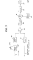
- Fig. 5 shows how the above-mentioned two rotary shutters 5 and 12 are driven.
- a single motor to simplify the driving system.
- a single electrical motor 20 is employed to drive both the rotary shutters 5 and 12 which are mechanically coupled with the drive motor 20.
- the relative rotational angle or position between these two rotary shutters 5 and 12 is first set and under this condition, these two rotary shutters 5 and 12 are mechanically coupled to be driven by the drive motor 20.
- the rotary shutter 5 is mounted on a drive shaft 20a of the motor 20, while the image-selecting rotary shutter 12 is mounted on a pulley 24 coupled by a belt 26 with another pulley 22 mounted on the drive shaft 20a of the motor 20.
- Fig. 6 is a schematic rear view showing the relationship between the two rotary shutters 5 and 12.
- the pulleys 22 and 24 are so called timing pulleys having equal number of gear teeth and are coupled by the belt 26 which is so called timing belt. In place of such belt-coupling may be used gear-coupling if desired.
- the image-selecting rotary shutter 12 is cup-shaped so that its peripheral edge is mounted on the pulley 24 which is annular shaped.
- the pulley 24 is rotatably supported via ball bearing 30 around an optical cylinder 28 in which the multi-lens assembly 8 is supported.
- the drive motor 20 is controlled by a speed control unit 18 responsive to a signal from a rotation sensor 34 positioned around the rotary shutter 5 to detect a recess or through-hole 32 made in the rotary shutter 5.
- This rotation sensor 34 may be a well known optical sensor having a light source and a photosensitive element (both not shown) to detect when the recess 32 passes.
- speed control is performed using the signal from the rotation sensor 34 and a vertical synchronous signal having a frequency of 60 Hz.
- Fig. 7 shows a block diagram of the speed control unit 18.
- the speed control unit 18 comprises a frequency divider 36 responsive to the output signal from the rotation sensor 34 so as to divide the frequency of the signal into two. In the case that 60 Hz signal is applied from the sensor 34, then the output signal from the frequency divider 36 is 30 Hz.
- To the speed control unit 18 is also applied the vertical sync signal of 60 Hz from a vertical sync signal generator 60 (see Fig. 5). This vertical sync signal is fed to a delay circuit 38 in which the amount of delay is adjustable, and a delayed vertical sync signal is fed to another frequency divider 40 so that the frequency is divided into two. As a result 30 Hz signal is obtained.
- EXCLUSIVE OR gate 42 Two output signals from the two frequency dividers 36 and 40 are fed to an EXCLUSIVE OR gate 42. An output signal from this EXCLUSIVE OR gate 42 is fed via an integrator 44 to an adder 46 to which a reference voltage from a reference voltage source 48 is applied. An output signal from the adder 46 obtained by adding the output signal from the integrator 44 to the reference voltage is then fed to a drive amplifier 50 to produce a drive current fed to the drive motor 20.
- the drive motor 20 is a d.c. motor whose rated speed is 3600 rpm.
- the delay circuit 38 is adjustable so that the amount of delay can be controlled by a control signal which may be manually produced using a potentiometer or the like.
- a control signal which may be manually produced using a potentiometer or the like.
- the delay circuit may be used a monostable multivibrator whose time constant is adjustable by a variable resistor 38a as shown in Fig. 7.
- the vertical sync signal is delayed in the illustrated embodiment, the signal from the rotation sensor 34 may be delayed instead to obtain substantially the same result.
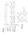
- Fig. 8A is a timing chart showing the relatinship between the vertical sync signal, and the positions of the two rotary shutters 5 and 12 in the case a CCD imager is used so that image information from all the pixels of the CCD imager is transferred at once during vertical blanking interval.
- the reference Atl indicates the phase difference between the vertical sync signal and the signal from the rotation sensor 34, and this phase difference corresponds to the time length of the delay to be delayed by the delay circuit 38 of the speed control unit of Fig. 7.
- Fig. 8B shows the rotational position of the image-selecting rotary shutter 12.
- the references 1 2 3 4 respectively indicate the position of the opening 12a, and these references are also shown in Fig. 8A to indicate that the image-selecting rotary shutter 12 rotates clockwise when viewed from the object 2. It is assumed that the recess 32 used for detecting the rotational angle of the rotary shutters 5 and 12 is provided between two slits or openings 5a and 5d which are used for positions 1 and 4 of the image-selecting rotary shutter 12.
- a CCD imager When a CCD imager, whose imaging area is shown by dotted lines, is used, the entire imaging area is subjected to exposure for storing charges in all the pixels depending on light intensity with the image-selecting rotary shutter 12 being rotated 360°. Then during the vertical blanking interval the stored charges are transferred to transfer gate in response to a given clock signal.
- the charge storing and transferring operation of the CCD imaging element is well known in the art, and further description thereof is omitted. It is to be noted, however, that four similar but different images are formed on the imaging element 11, and therefore, a resultant output signal from the CCD imager 11 includes such picture information including four different images.
- Figs. 9A and 9B are diagrams similar to Figs. 8A and 8B.
- the timing chart of Fig. 9A and the view of the image-selecting rotary shutter 12 of Fig. 9B are used for describing the operation when a pickup tube is used instead of the CCD imager as the pickup element 11.
- a time length corresponding to the phase difference ⁇ t2 between the vertical sync signal and the signal from the rotation sensor 34 is delayed by the delay circuit 38 of Fig. 7 in the same manner as described in the above.
- a picture area of the picture tube is shown by dotted lines.
- upper half of the picture area is used for reading information, i.e. scanning is performed in the upper half
- a lower half of the same is exposed to receive optical information given through the opening 12a.
- the upper half is exposed.
- upper and lower halves of the picture area of the picture tube are alternately used for writing (exposure) and reading (scanning). To this end, a larger amount of delay is required as the delay time given by the delay circuit 38.
- the rotary shutter has four openings 5a - 5d, the same effect can be obtained when a rotatry shutter having only two openings is rotated at a speed twice the speed of the rotary shutter 12.
- the angle of the opening subtending with respect to the center of rotary shutter has to be twice that of the rotary shutter 12 so as to provide the shutter speed of 1/1080 second.
- Fig. 10 shows.a front view of a monitor television 13 on which CRT screen are imaged four different images respectively picked up by the four areas of the CCD imager or the pickup tube used in place of the CCD imager. More specifically, the four different images 1 2 3 and 4 are first obtained in sequence at an interval of 1/240 second within a period of 1/60 second since the four real images respectively obtained by the four lenses 8a - 8d of the multi-lens assembly 8 are applied in a given order as the image-selecting rotary shutter 12 rotates.
- this speed can be increased by increasing the number of lenses of the multi-lens assembly. For instance, when 8 lenses are arranged in an annular fashion to form a multi-lens assembly, the angle of the opening 12a of the image-selecting rotary shutter 12 is reduced to 45°, and the number of openings of the other rotary shutter 5 is increased to 8. In this way, each image is taken at a speed of 1/480 second so that 8 images are taken during 1/60 second. This is just an example, and therefore, a shutter speed higher than 1/480 can also be provided in a similar manner.
- Fig. 11 illustrates a second embodiment video camera accoding to the present invention.
- This second embodiment mainly differs from the first embodiment of Fig. 1 in that the multi-lens assembly 8 is replaced with a prism 14 having four light-receiving surfaces 14a - 14d which are inclined with respect to its rear surface.
- Fig. 12 is a top plan view of the prism 14.
- this prism 14 may be used one known as "Mirage” manufactured by Kenko Filter Inc. of Japan.
- This prism known as "Mirage” is used in combination with a television camera when it is intended to arrange a plurality of an identical image within a single picture to make visionary scene.
- the prism 14 having four light-receiving surfaces 14a - 14d operates as a beam splitter in the same manner as the multi-lens assembly 8 of the first embodiment. Therefore, four images are produced which are selectively transmitted in sequence through the opening 12a of the image-selecting rotary shutter 12. As a result, four different images are formed on the imaging plane lla of the image pickup device 11 within a period of 1/60 second in the same manner as in the first embodiment.
- the reference 15 is a close up lens used for forming the images successively transmitted through the opening 12a with the length of each side of the images being reduced to one half.
- the light beam of a real image of the object 2 is split into a plurality, and resulted images formed by the plurality of beams are passed through the opening 12a of the image-selecting rotary shutter 12 in sequence.
- a plurality of images are formed on a picture imaging plane of the pickup element or device 11, such as a solid state imager or a pickup tube where each image has time difference such as 1/240 second in the case that four images are produced for the single object 2. Therefore, it is advantageous for analysis of an ojbect moving or varying at a very high speed.
- the high speed image taking system according to the present invention requires only the change in the optical system of a video camera without changing the system of image pickup, high speed image pickup and reproduction can be performed readily at a low cost.
- various manipulation and operation such as focussing, adjustment of diaphragm and zooming may be simple when compared with a conventional system using a plurality of video cameras.
- the main lens can be readily replaced with another having different focal length.
Landscapes
- Engineering & Computer Science (AREA)
- Multimedia (AREA)
- Signal Processing (AREA)
- Transforming Light Signals Into Electric Signals (AREA)
- Shutters For Cameras (AREA)
Applications Claiming Priority (2)
| Application Number | Priority Date | Filing Date | Title |
|---|---|---|---|
| JP243593/84 | 1984-11-19 | ||
| JP59243593A JPS61121668A (ja) | 1984-11-19 | 1984-11-19 | ビデオカメラ |
Publications (3)
| Publication Number | Publication Date |
|---|---|
| EP0182334A2 true EP0182334A2 (fr) | 1986-05-28 |
| EP0182334A3 EP0182334A3 (en) | 1987-09-02 |
| EP0182334B1 EP0182334B1 (fr) | 1991-10-09 |
Family
ID=17106120
Family Applications (1)
| Application Number | Title | Priority Date | Filing Date |
|---|---|---|---|
| EP85114627A Expired - Lifetime EP0182334B1 (fr) | 1984-11-19 | 1985-11-18 | Caméra de vidéo à haute vitesse et procédé de prise de vues à haute vitesse utilisant un fractionneur de rayons |
Country Status (4)
| Country | Link |
|---|---|
| US (1) | US4646156A (fr) |
| EP (1) | EP0182334B1 (fr) |
| JP (1) | JPS61121668A (fr) |
| DE (1) | DE3584350D1 (fr) |
Cited By (5)
| Publication number | Priority date | Publication date | Assignee | Title |
|---|---|---|---|---|
| FR2623302A1 (fr) * | 1987-11-17 | 1989-05-19 | Angenieux P Ets | Objectif pour camera de television |
| EP0638838A1 (fr) * | 1993-08-09 | 1995-02-15 | Eastman Kodak Company | Obturateur destiné à être utilisé avec matériau photosensible |
| EP0704133A4 (fr) * | 1993-05-18 | 1996-07-10 | Intevac Inc | Systeme de surveillance possedant un tube intensificateur d'image a microcanal |
| FR2773658A1 (fr) * | 1998-01-13 | 1999-07-16 | Univ Lille Sciences Tech | Procede d'acquisition d'images ultra-rapide a base d'un capteur matriciel a semi-conducteurs, type ccd, et dispositif pour la mise en oeuvre de ce procede |
| WO2013095309A1 (fr) * | 2011-08-10 | 2013-06-27 | Buyuksahin Utku | Appareil d'augmentation de fréquence d'image pour caméras |
Families Citing this family (5)
| Publication number | Priority date | Publication date | Assignee | Title |
|---|---|---|---|---|
| US4812911A (en) * | 1986-01-28 | 1989-03-14 | Canon Kabushiki Kaisha | Adapter with built-in shutter |
| US4695887A (en) * | 1986-11-13 | 1987-09-22 | Eastman Kodak Company | Variable speed video camera |
| US8436905B2 (en) * | 2002-09-20 | 2013-05-07 | Bae Systems Information And Electronic Systems Integration Inc. | Front lens shutter mount for uniformity correction |
| US7453510B2 (en) * | 2003-12-11 | 2008-11-18 | Nokia Corporation | Imaging device |
| US7777199B2 (en) * | 2004-09-17 | 2010-08-17 | Wichita State University | System and method for capturing image sequences at ultra-high framing rates |
Family Cites Families (6)
| Publication number | Priority date | Publication date | Assignee | Title |
|---|---|---|---|---|
| US3303271A (en) * | 1964-05-21 | 1967-02-07 | Klaus J Hecker | Rotary shutter arrangement providing a plurality of frame rates |
| US3443499A (en) * | 1966-10-12 | 1969-05-13 | Polaroid Corp | Exposure control apparatus for photographic camera |
| GB1211598A (en) * | 1967-10-11 | 1970-11-11 | Ricoh Kk | Improvements in and relating to photographic arrangements |
| US4301476A (en) * | 1980-09-29 | 1981-11-17 | Keller Patrick N | Phase controlled shuttering system with selectable shuttered and unshuttered modes |
| US4589030A (en) * | 1983-07-25 | 1986-05-13 | Kley Victor B | Solid state camera |
| US4597015A (en) * | 1984-04-27 | 1986-06-24 | Rca Corporation | Image sensitivity for shuttered solid-state imager television camera |
-
1984
- 1984-11-19 JP JP59243593A patent/JPS61121668A/ja active Pending
-
1985
- 1985-11-18 EP EP85114627A patent/EP0182334B1/fr not_active Expired - Lifetime
- 1985-11-18 DE DE8585114627T patent/DE3584350D1/de not_active Expired - Fee Related
- 1985-11-18 US US06/799,164 patent/US4646156A/en not_active Expired - Fee Related
Cited By (7)
| Publication number | Priority date | Publication date | Assignee | Title |
|---|---|---|---|---|
| FR2623302A1 (fr) * | 1987-11-17 | 1989-05-19 | Angenieux P Ets | Objectif pour camera de television |
| EP0704133A4 (fr) * | 1993-05-18 | 1996-07-10 | Intevac Inc | Systeme de surveillance possedant un tube intensificateur d'image a microcanal |
| EP0638838A1 (fr) * | 1993-08-09 | 1995-02-15 | Eastman Kodak Company | Obturateur destiné à être utilisé avec matériau photosensible |
| US5914750A (en) * | 1993-08-09 | 1999-06-22 | Eastman Kodak Company | Shutter including a capping element movable between light-blocking and non-light-blocking positions |
| FR2773658A1 (fr) * | 1998-01-13 | 1999-07-16 | Univ Lille Sciences Tech | Procede d'acquisition d'images ultra-rapide a base d'un capteur matriciel a semi-conducteurs, type ccd, et dispositif pour la mise en oeuvre de ce procede |
| WO1999037089A1 (fr) * | 1998-01-13 | 1999-07-22 | Universite Des Sciences Et Technologies De Lille | Procede d'acquisition ultra-rapide d'une sequence d'images au moyen d'un capteur matriciel a semi-conducteurs, type ccd, et dispositif pour la mise en oeuvre de ce procede |
| WO2013095309A1 (fr) * | 2011-08-10 | 2013-06-27 | Buyuksahin Utku | Appareil d'augmentation de fréquence d'image pour caméras |
Also Published As
| Publication number | Publication date |
|---|---|
| EP0182334B1 (fr) | 1991-10-09 |
| DE3584350D1 (de) | 1991-11-14 |
| JPS61121668A (ja) | 1986-06-09 |
| US4646156A (en) | 1987-02-24 |
| EP0182334A3 (en) | 1987-09-02 |
Similar Documents
| Publication | Publication Date | Title |
|---|---|---|
| US7791638B2 (en) | Rotating scan camera | |
| US7525567B2 (en) | Recording a stereoscopic image of a wide field of view | |
| US4485406A (en) | Film video player with zoom and scan | |
| US5721585A (en) | Digital video panoramic image capture and display system | |
| US4057830A (en) | Electronic photography system | |
| US7148916B2 (en) | Photographing system | |
| US6545701B2 (en) | Panoramic digital camera system and method | |
| US4646156A (en) | High-speed video camera and method of high-speed imaging using a beam splitter | |
| EP0397647B1 (fr) | Procede de transfert de film sur video | |
| JPH06225202A (ja) | パノラマ電子スチルカメラ | |
| JPS6027278A (ja) | 固体撮像カメラ | |
| JPH06326900A (ja) | 撮像装置 | |
| JPH0630446A (ja) | 立体画像記録装置 | |
| JPS636859B2 (fr) | ||
| WO2000010054A1 (fr) | Procede de transfert video-film | |
| JPH09322198A (ja) | 3次元立体映像信号変換装置及び該装置を用いる映像モニター装置 | |
| JPS59202775A (ja) | 高速ビデオ録画装置 | |
| JP3416348B2 (ja) | 立体撮像装置 | |
| JPH04329079A (ja) | 磁気記録撮影装置 | |
| JPS61121674A (ja) | 高速度画像録画再生方式 | |
| JPH03143172A (ja) | ビデオカメラ | |
| JPS5827710B2 (ja) | サツゾウホウホウ | |
| JPH10257369A (ja) | 画像信号記録装置、記録再生装置および記録方法 | |
| KR900007639B1 (ko) | 입체영상 더빙장치 | |
| JPS6072379A (ja) | 電子カメラ |
Legal Events
| Date | Code | Title | Description |
|---|---|---|---|
| PUAI | Public reference made under article 153(3) epc to a published international application that has entered the european phase |
Free format text: ORIGINAL CODE: 0009012 |
|
| AK | Designated contracting states |
Kind code of ref document: A2 Designated state(s): DE FR GB |
|
| PUAL | Search report despatched |
Free format text: ORIGINAL CODE: 0009013 |
|
| AK | Designated contracting states |
Kind code of ref document: A3 Designated state(s): DE FR GB |
|
| 17P | Request for examination filed |
Effective date: 19880128 |
|
| 17Q | First examination report despatched |
Effective date: 19900418 |
|
| GRAA | (expected) grant |
Free format text: ORIGINAL CODE: 0009210 |
|
| AK | Designated contracting states |
Kind code of ref document: B1 Designated state(s): DE FR GB |
|
| ET | Fr: translation filed | ||
| REF | Corresponds to: |
Ref document number: 3584350 Country of ref document: DE Date of ref document: 19911114 |
|
| PLBE | No opposition filed within time limit |
Free format text: ORIGINAL CODE: 0009261 |
|
| STAA | Information on the status of an ep patent application or granted ep patent |
Free format text: STATUS: NO OPPOSITION FILED WITHIN TIME LIMIT |
|
| 26N | No opposition filed | ||
| PGFP | Annual fee paid to national office [announced via postgrant information from national office to epo] |
Ref country code: GB Payment date: 19921106 Year of fee payment: 8 |
|
| PGFP | Annual fee paid to national office [announced via postgrant information from national office to epo] |
Ref country code: FR Payment date: 19921109 Year of fee payment: 8 |
|
| PGFP | Annual fee paid to national office [announced via postgrant information from national office to epo] |
Ref country code: DE Payment date: 19921212 Year of fee payment: 8 |
|
| PG25 | Lapsed in a contracting state [announced via postgrant information from national office to epo] |
Ref country code: GB Effective date: 19931118 |
|
| GBPC | Gb: european patent ceased through non-payment of renewal fee |
Effective date: 19931118 |
|
| PG25 | Lapsed in a contracting state [announced via postgrant information from national office to epo] |
Ref country code: FR Effective date: 19940729 |
|
| PG25 | Lapsed in a contracting state [announced via postgrant information from national office to epo] |
Ref country code: DE Effective date: 19940802 |
|
| REG | Reference to a national code |
Ref country code: FR Ref legal event code: ST |