EP0182345A2 - Improved channel inductor block for channel induction furnace and method of making same - Google Patents
Improved channel inductor block for channel induction furnace and method of making same Download PDFInfo
- Publication number
- EP0182345A2 EP0182345A2 EP85114660A EP85114660A EP0182345A2 EP 0182345 A2 EP0182345 A2 EP 0182345A2 EP 85114660 A EP85114660 A EP 85114660A EP 85114660 A EP85114660 A EP 85114660A EP 0182345 A2 EP0182345 A2 EP 0182345A2
- Authority
- EP
- European Patent Office
- Prior art keywords
- refractory
- inductor block
- inductor
- temperature
- block
- Prior art date
- Legal status (The legal status is an assumption and is not a legal conclusion. Google has not performed a legal analysis and makes no representation as to the accuracy of the status listed.)
- Withdrawn
Links
Images


Classifications
-
- H—ELECTRICITY
- H05—ELECTRIC TECHNIQUES NOT OTHERWISE PROVIDED FOR
- H05B—ELECTRIC HEATING; ELECTRIC LIGHT SOURCES NOT OTHERWISE PROVIDED FOR; CIRCUIT ARRANGEMENTS FOR ELECTRIC LIGHT SOURCES, IN GENERAL
- H05B6/00—Heating by electric, magnetic or electromagnetic fields
- H05B6/02—Induction heating
- H05B6/16—Furnaces having endless cores
- H05B6/20—Furnaces having endless cores having melting channel only
-
- C—CHEMISTRY; METALLURGY
- C04—CEMENTS; CONCRETE; ARTIFICIAL STONE; CERAMICS; REFRACTORIES
- C04B—LIME, MAGNESIA; SLAG; CEMENTS; COMPOSITIONS THEREOF, e.g. MORTARS, CONCRETE OR LIKE BUILDING MATERIALS; ARTIFICIAL STONE; CERAMICS; REFRACTORIES; TREATMENT OF NATURAL STONE
- C04B35/00—Shaped ceramic products characterised by their composition; Ceramics compositions; Processing powders of inorganic compounds preparatory to the manufacturing of ceramic products
- C04B35/01—Shaped ceramic products characterised by their composition; Ceramics compositions; Processing powders of inorganic compounds preparatory to the manufacturing of ceramic products based on oxide ceramics
- C04B35/10—Shaped ceramic products characterised by their composition; Ceramics compositions; Processing powders of inorganic compounds preparatory to the manufacturing of ceramic products based on oxide ceramics based on aluminium oxide
- C04B35/101—Refractories from grain sized mixtures
-
- C—CHEMISTRY; METALLURGY
- C04—CEMENTS; CONCRETE; ARTIFICIAL STONE; CERAMICS; REFRACTORIES
- C04B—LIME, MAGNESIA; SLAG; CEMENTS; COMPOSITIONS THEREOF, e.g. MORTARS, CONCRETE OR LIKE BUILDING MATERIALS; ARTIFICIAL STONE; CERAMICS; REFRACTORIES; TREATMENT OF NATURAL STONE
- C04B35/00—Shaped ceramic products characterised by their composition; Ceramics compositions; Processing powders of inorganic compounds preparatory to the manufacturing of ceramic products
- C04B35/66—Monolithic refractories or refractory mortars, including those whether or not containing clay
-
- F—MECHANICAL ENGINEERING; LIGHTING; HEATING; WEAPONS; BLASTING
- F27—FURNACES; KILNS; OVENS; RETORTS
- F27D—DETAILS OR ACCESSORIES OF FURNACES, KILNS, OVENS OR RETORTS, IN SO FAR AS THEY ARE OF KINDS OCCURRING IN MORE THAN ONE KIND OF FURNACE
- F27D1/00—Casings; Linings; Walls; Roofs
- F27D1/0003—Linings or walls
- F27D1/0006—Linings or walls formed from bricks or layers with a particular composition or specific characteristics
-
- C—CHEMISTRY; METALLURGY
- C04—CEMENTS; CONCRETE; ARTIFICIAL STONE; CERAMICS; REFRACTORIES
- C04B—LIME, MAGNESIA; SLAG; CEMENTS; COMPOSITIONS THEREOF, e.g. MORTARS, CONCRETE OR LIKE BUILDING MATERIALS; ARTIFICIAL STONE; CERAMICS; REFRACTORIES; TREATMENT OF NATURAL STONE
- C04B2235/00—Aspects relating to ceramic starting mixtures or sintered ceramic products
- C04B2235/02—Composition of constituents of the starting material or of secondary phases of the final product
- C04B2235/30—Constituents and secondary phases not being of a fibrous nature
- C04B2235/32—Metal oxides, mixed metal oxides, or oxide-forming salts thereof, e.g. carbonates, nitrates, (oxy)hydroxides, chlorides
- C04B2235/3217—Aluminum oxide or oxide forming salts thereof, e.g. bauxite, alpha-alumina
-
- C—CHEMISTRY; METALLURGY
- C04—CEMENTS; CONCRETE; ARTIFICIAL STONE; CERAMICS; REFRACTORIES
- C04B—LIME, MAGNESIA; SLAG; CEMENTS; COMPOSITIONS THEREOF, e.g. MORTARS, CONCRETE OR LIKE BUILDING MATERIALS; ARTIFICIAL STONE; CERAMICS; REFRACTORIES; TREATMENT OF NATURAL STONE
- C04B2235/00—Aspects relating to ceramic starting mixtures or sintered ceramic products
- C04B2235/02—Composition of constituents of the starting material or of secondary phases of the final product
- C04B2235/30—Constituents and secondary phases not being of a fibrous nature
- C04B2235/32—Metal oxides, mixed metal oxides, or oxide-forming salts thereof, e.g. carbonates, nitrates, (oxy)hydroxides, chlorides
- C04B2235/3217—Aluminum oxide or oxide forming salts thereof, e.g. bauxite, alpha-alumina
- C04B2235/3222—Aluminates other than alumino-silicates, e.g. spinel (MgAl2O4)
-
- C—CHEMISTRY; METALLURGY
- C04—CEMENTS; CONCRETE; ARTIFICIAL STONE; CERAMICS; REFRACTORIES
- C04B—LIME, MAGNESIA; SLAG; CEMENTS; COMPOSITIONS THEREOF, e.g. MORTARS, CONCRETE OR LIKE BUILDING MATERIALS; ARTIFICIAL STONE; CERAMICS; REFRACTORIES; TREATMENT OF NATURAL STONE
- C04B2235/00—Aspects relating to ceramic starting mixtures or sintered ceramic products
- C04B2235/02—Composition of constituents of the starting material or of secondary phases of the final product
- C04B2235/30—Constituents and secondary phases not being of a fibrous nature
- C04B2235/34—Non-metal oxides, non-metal mixed oxides, or salts thereof that form the non-metal oxides upon heating, e.g. carbonates, nitrates, (oxy)hydroxides, chlorides
- C04B2235/3418—Silicon oxide, silicic acids or oxide forming salts thereof, e.g. silica sol, fused silica, silica fume, cristobalite, quartz or flint
Definitions
- This invention relates to channel induction furnaces. More particularly, this invention relates to an improved channel inductor block for use in the inductor portion of a channel induction furnace and a method of making the channel inductor block.
- a channel induction furnace can also be used for this purpose.
- a typical channel induction furnace includes an inductor portion which functions as a transformer or inductor with a magnetic iron core and a primary coil assembly on the core which passes through a refractory block containing an annular secondary cavity or "channel" for the melt.
- This channel contains molten metal, such as molten aluminum, which forms the secondary winding for the transformer.
- the induced magnetic field in the molten metal secondary not only heats the aluminum but causes circulation of the molten aluminum throughout the furnace resulting in exceptional composition and temperature uniformity throughout the furnace.
- Such channel inductor furnaces are described in Tama U.S. Patent 2,347,298 and Tama et al U.S. Patent 3,092,682.
- the refractory erosion resulting from contact with molten aluminum being circulated at high velocity through the channels is also, at least in part, due to the choice of refractory materials used and the curing method employed to develop good physical properties.
- refractory materials have been dry rammed and fired in place with a burnout channel core pattern, such as wood, used for the channels themselves with the primary coils of the inductor continuously water cooled for protection. It has, therefore, been impossible to properly cure the refractory materials to any appreciable thickness.
- curing was done with manual heating means to both burn out the wood form and cure the refractory while simultaneously cooling the inductor coils.
- Examples of castable refractory materials which exhibit excellent corrosion resistance when in contact with molten aluminum include the types of materials described in LaBar U.S. Patents 4,088,502 and 4,158,568 and Hines et al U.S. Patent 4,348,236. However, to achieve the resistance to corrosion from molten aluminum which these castable refractory materials are capable of exhibiting, it is necessary that the refractory material be properly and uniformly fired throughout the material.
- an improved refractory inductor block for a channel induction furnace for melting aluminum comprising a hearth and an inductor having a magnetic iron core and a primary coil assembly passing through openings in a refractory inductor block containing channels through which pass molten aluminum and which comprises a secondary winding magnetically coupled to said primary coil assembly, characterized by said improved refractory inductor block being formed from a refractory mix resistant to corrosion by molten aluminum comprising 9.5 to 40 wt.% calcium aluminate, 0.5 to 10 wt.% of a borosilicate frit and 60 to 90 wt.% of an aggregate selected from the group consisting of alumina-bearing compounds, silica-bearing compounds, and mixtures thereof.
- an improved refractory inductor block for a channel induction furnace exhibiting an enhanced resistance to deterioration by contact with molten aluminum characterized by said improved refractory inductor block comprising a uniformly fired ceramic formed from a refractory mix resistant to corrosion by molten aluminum comprising calcium aluminate, alumina and a borosilicate frit, in a ratio sufficient to maintain said resistance to corrosion by molten aluminum, cast around a channel core pattern capable of desolidifying when exposed to elevated temperatures to form channels in said refractory inductor block, said mix being fired at a temperature of from 760 to 871°C. (1400 to 1600°F.) for from 5 to 20 hours to fire said refractory inductor block, said resultant fired refractory inductor block being capable of withstanding deterioration from contact with molten aluminum.
- a method for making a refractory inductor block for a channel induction furnace for melting aluminum wherein an inductor comprises a magnetic iron core and a primary coil assembly mounted in openings in a refractory inductor block to provide magnetic coupling to a secondary winding comprising molten aluminum in channels formed in said refractory inductor block, characterized by comprising forming said refractory inductor block using removable channel core patterns and refractory material resistant to corrosion by molten aluminum comprising 9.5 to 40 wt.% calcium aluminate, 0.5 to 10 wt.% of a borosilicate frit and 60 to 90 wt.% of an aggregate selected from the group consisting of alumina-bearing compounds, silica-bearing compounds, and mixtures thereof whereby deterioration of said refractory inductor block, by said molten aluminum flowing through said channels, will be inhibited.
- an improved method for making a refractory inductor block for a channel induction furnace exhibiting an enhanced resistance to deterioration by contact with molten aluminum characterized by comprising the steps of:
- an improvement is provided in channel induction furnaces for melting aluminum having a hearth and an inductor.
- the inductor comprises a magnetic iron core and a primary coil assembly passing through openings in a refractory inductor block containing channels through which passes molten aluminum which comprises a secondary winding magnetically coupled to the primary coil assembly.
- the improvement comprises casting the refractory inductor block from a corrosion resistant refractory consisting essentially of 9.5 to 40 wt.% calcium aluminate, 0.5 to 10% of a borosilicate frit, and 60 to 90 wt.% of an aggregate selected from the group consisting of alumina-bearing or silica-bearing compounds or mixtures thereof.
- the corrosion resistant refractory mix consists essentially of 10 to 20 wt.% calcium aluminate, 0.5 to 1.5 wt.% of a borosilicate frit, and 79.5 to 89.5 wt.% alumina.
- the refractory is cast around a solid core pattern made from a material capable of desolidifying upon the application of heat, such as a wax core.
- the channel core pattern is shaped to provide the desired channels within the refractory inductor block.
- the core pattern material such as wax
- the core pattern material may be melted off and the refractory cured by firing at a temperature of from 760 to 871°C (1400 to 1600°F), preferably about 815.5°C (1500°F) for from 5 to 20 hours and preferably about 6 hours.
- the temperature is slowly raised from ambient up to the firing temperature at a rate of-up to about 5.6°C. (10°F. per hour).
- a channel induction furnace is generally indicated at 2 comprising a detachable upper hearth portion 6 and a lower inductor portion 10.
- Inductor 10 includes a casing 60 having mounted therein refractory 20 having channels 30 therein through which molten aluminum flows as the secondary winding of a transformer or inductor.
- An iron core 40 is threaded through openings 24 and 26 in inductor lining 20. Iron core 40 carries primary coils 50 and 52 thereon.
- a channel core pattern 80 which, in accordance with one aspect of the invention, comprises a low melting material, such as a paraffin wax material, which may be used to form channels 30 in the refractory inductor block of the invention.
- Core pattern 80 includes a large diameter central portion 82 which will form the central channel 32 and reduced diameter wing portions 86 and 88 which will, respectively, form channels 36 and 38 in the resultant inductor block. Materials other than wax may be used for channel core pattern 80.
- channel core pattern 80 should be made of a material which can be removed by desolidifying, such as by volatilizing or decomposing or the like, without leaving any substantial residue upon exposure to heat rather than charring or burning as might be the case with materials, such as wood or some plastics.
- the material chosen will be one which will, upon its removal, leave a very smooth surface in the refractory inductor block channels to permit streamlined nonturbulent flow of the molten aluminum without providing ridges or discontinuities which may cause erosion and wear.
- channel core pattern 80 of low melting material a wood pattern designed and constructed by the inductor manufacturer may be purchased and used to make a plaster split mold. This plaster mold is then used to form the channel core pattern 80 made of low melting material, such as paraffin wax. Large diameter machine screws 96 are cast into the top portion of the center channel 82 and the side channels 86 and 88 using the top mold block 120 as a template. These screws then properly locate and hold the top mold block 120 and transition members 90 and 92 to the channel core pattern 80 during the refractory casting.
- low melting material such as paraffin wax
- the refractory mix used in forming the inductor block comprises a mixture of calcim aluminate, borosilicate frit and an aggregate selected from the group consisting of an alumina-bearing compound, a silica-bearinj compound and mixtures thereof.
- the mixture preferably consists essentially of 74.5 to 90%, and preferably 79.5 to 89.5 wt.X alumina, 9.5 to 25 wt.%, and preferably 10 to 20 wt.X calcium aluminate and 0.5 to 1.5 wt.X borosilicate frit.
- alumina When alumina is utilized as the aggregate, it may be tabular alumina, and its particle size is preferably controlled such that 20 to 40 wt.% of the alumina particles are between 1.41 mm and 4.76 mm in size, 15 to 30 wt.% are between 0.297 mm and 1.41 mm in size, and 25 to 40 wt.X are less than 0.297 mm in size.
- silica When silica is used as the aggregate, it may be used in a particle size range of about -4 mesh (U.S. Standard).
- the silica particle mixture contains about 50 wt.% particles of -10 to +325 mesh with the balance smaller. Most preferably, about 20 to 30 wt.% of the particles are -10 to +20 mesh, about 15 to 25 wt.% -20 to +100 mesh and the balance -100 mesh.
- the calcium aluminate which is used in the invention may be obtained from a variety of commercial sources.
- the calcium aluminate comprises a mixture of 75 to 83 wt.% aluminum oxide and 14 to 23 wt.% calcium oxide, with a total of no more than 3 wt.X of other oxides, primarily zinc oxide, boron oxide and silicon dioxide.
- Such a calcium aluminate product is sold by the Aluminum Company of America under the designation "CA-25".
- the particle size of the calcium aluminate is preferably controlled so that at least 90 wt.X is less than 0.044 mm.
- the borosilicate frit consists essentially of 15 to 35 wt.% boron oxide; 5 to 30 wt.% silicon dioxide; 10 to 60 wt.% of a metal selected from the class consisting of zinc oxide, lead oxide and calcium oxide; and a total of no more than 20 wt.% alkali compounds, such as lithium oxide, sodium oxide and potassium oxide.
- the preferred frit also contains 5 to 25 wt.% fluorine, and its particle size is controlled to less than 0.149 mm.
- the top throat mold 120, the transition pieces 90 and 92 and the channel core pattern 80 are all assembled and anchored upside down in mold 100, as shown in Figure 4.
- the coil core mold pieces 110 are then placed in mold 100 and anchored to the sidewalls 104 of mold 100.
- the refractory mix is then poured into the mold using a stick vibrator during the fill to make sure all air bubbles have been removed and that the fill is complete.
- the refractory material is first cured for a period of from 6 to 10 hours at from about 21 to 32°C (70 to 90°F.) and then dried to remove physically absorbed water for from 20 to 30 hours at from 35 to 110°C (95 to 230°F).
- Top mold block 120 and transition pieces 90 and 92 are then removed, and mold blocks 110 are removed through the sidewall of container mold 100.
- the green refractory inductor block 20 is then removed from container mold 100.
- the resulting green refractory inductor block 20 only contains channel core pattern 80 therein which may be melted out prior to the firing operation.
- the green refractory inductor block 20, as seen in Figure 5, in accordance with the invention, is now fired.
- the firing is carried out at a temperature of from about 760 to 871°C (1400 to 1600°F), preferably about 815.5°C (1500°F), for from 5 to 20 hours, preferably 6 hours. Most preferably, the firing is done at 815.5°C (1500°F) for 6 hours with a maximum temperature variation of + 2.78°C (5°F).
- the green refractory is brought up to the firing temperature slowly at a rate of about 5.6°C (10°F) climb per hour until the 815.5°C (1500°F) firing temperature is reached. After the firing time has elapsed, the furnace is shut off, and the fired refractory inductor block 20 is allowed to cool, on its own in the closed furnace, back to ambient temperature.
- Refractory inductor block 20 is now ready for installation in casing 60, as shown in Figure 6.
- the bottom castable insulation layer 72 is poured into casing 60 to the proper depth (12 inches) and permitted to air dry and harden.
- Inductor block 20 is positioned in casing 60 on insulation layer 72 and a castable insulation material 70, such as a calcium aluminate mixture, is poured into casing 60 around refractory inductor block 20 to hold block 20 in place.
- a castable insulation material 70 such as a calcium aluminate mixture
- insulation materials 70 and 72 need not be precisely fired and cured to properly function, in contrast to the prior art rammed mix procedure, because insulation 70 and 72 do not come in contact with the molten aluminum.
- the function of insulation 70 and 72 is to hold refractory inductor block 20 in alignment with casing 60 and provide thermal insulation for the whole system.
- iron core 40 with coils 50 and 52 thereon are mounted through openings 24 and 26 in block 20 and the corresponding openings in casing 60.
- Hearth member 6 is then secured to inductor 10, coils 50 and 52 connected to an external power source, and molten aluminum is poured into preheated hearth 6 to enter the channels 30 formed in induction block 20 to form the secondary coil of the transformer or inductor.
- molten aluminum is poured into preheated hearth 6 to enter the channels 30 formed in induction block 20 to form the secondary coil of the transformer or inductor.
- a refractory inductor block was cast from a mixture consisting essentially (in wt.%) of 80 to 85% alumina, 14 to 18% calcium aluminate and 0.5 to 1.5% of a borosilicate frit consisting essentially of about 21.5% B 2 0 3 , 12.2X F, 15.3% Na 2 0, 3.0% MgO, 0.7% A1203, 25.1% Si0 2 and 22.2% CaO.
- the dry refractory mixture was blended with an amount of water equal to about 5 to 8 wt.X of the dry mix weight.
- the mixture was cast around a wax channel core pattern and cured at 21 to 32°C for about 8 hours.
- the cured block was then dried to remove physically absorbed water for about 24 hours at 35 to 110°C.
- the channel core pattern was melted out by heating to 135°C.
- the block was then fired by raising the temperature in a shuttle kiln from ambient about 5.6°C (10°F) per hour up to 815.5°C (1500°F).
- the refractory was fired for 6 hours while maintaining this temperature + 2.78°C (+ 5°F).
- the block was allowed to cool back to room temperature.
- the resultant fired refractory inductor block was then mounted in a channel induction furnace, which was operated successfully for 225 days not limited by refractory life and far beyond that previously experienced with prior art lining types.
- the invention provides an improved refractory inductor block and a method of making same wherein a refractory mix capable, after firing, of withstanding corrosion and erosion by contact with molten aluminum, is molded around a channel core pattern made from a material, such as wax, capable of desolidifying upon the application of heat.
- the green refractory block is heated to remove the channel core pattern and then further heated under carefully controlled conditions to uniformly fire the refractory to obtain the desired properties of corrosion and abrasion resistance to molten aluminum in finished refractory inductor block product.
Landscapes
- Engineering & Computer Science (AREA)
- Chemical & Material Sciences (AREA)
- Ceramic Engineering (AREA)
- Organic Chemistry (AREA)
- Manufacturing & Machinery (AREA)
- Materials Engineering (AREA)
- Structural Engineering (AREA)
- Electromagnetism (AREA)
- Physics & Mathematics (AREA)
- Mechanical Engineering (AREA)
- General Engineering & Computer Science (AREA)
- Furnace Details (AREA)
- Vertical, Hearth, Or Arc Furnaces (AREA)
- Manufacture And Refinement Of Metals (AREA)
- Compositions Of Oxide Ceramics (AREA)
- Furnace Housings, Linings, Walls, And Ceilings (AREA)
Abstract
Description
- This invention relates to channel induction furnaces. More particularly, this invention relates to an improved channel inductor block for use in the inductor portion of a channel induction furnace and a method of making the channel inductor block.
- The melting of aluminum for the formation of alloys or processing of aluminum scrap is conventionally accomplished using fossil fueled furnaces, electric resistance furnaces, or coreless induction furnaces. A channel induction furnace can also be used for this purpose. A typical channel induction furnace includes an inductor portion which functions as a transformer or inductor with a magnetic iron core and a primary coil assembly on the core which passes through a refractory block containing an annular secondary cavity or "channel" for the melt. This channel contains molten metal, such as molten aluminum, which forms the secondary winding for the transformer. The induced magnetic field in the molten metal secondary not only heats the aluminum but causes circulation of the molten aluminum throughout the furnace resulting in exceptional composition and temperature uniformity throughout the furnace. Such channel inductor furnaces are described in Tama U.S. Patent 2,347,298 and Tama et al U.S. Patent 3,092,682.
- In the past, however, problems have arisen with regard to plugging of the channels in the inductor block with oxides particularly when the furnace was used to melt aluminum. This problem has been largely overcome by streamlining the design of the channels and designing the primary coil windings to circulate the molten aluminum at high velocities. However, the refractory material used to form the channel through which the molten aluminum flows has been subject to erosion problems due to difficulties associated with the firing of the refractory. This erosion has been exacerbated by the increased velocities employed to avoid plugging of the channels, resulting in further erosion and shorter life for the refractory.
- The refractory erosion resulting from contact with molten aluminum being circulated at high velocity through the channels, is also, at least in part, due to the choice of refractory materials used and the curing method employed to develop good physical properties. In the past, refractory materials have been dry rammed and fired in place with a burnout channel core pattern, such as wood, used for the channels themselves with the primary coils of the inductor continuously water cooled for protection. It has, therefore, been impossible to properly cure the refractory materials to any appreciable thickness. Usually, curing was done with manual heating means to both burn out the wood form and cure the refractory while simultaneously cooling the inductor coils. This method, however, results in nonuniform firing temperatures being applied to the refractory material throughout its thickness. In some instances, a more corrosion resistant castable material might exist but could not be employed because of increased shrinkage and the probability of water remaining due to uneven refractory dryout.
- Examples of castable refractory materials which exhibit excellent corrosion resistance when in contact with molten aluminum include the types of materials described in LaBar U.S. Patents 4,088,502 and 4,158,568 and Hines et al U.S. Patent 4,348,236. However, to achieve the resistance to corrosion from molten aluminum which these castable refractory materials are capable of exhibiting, it is necessary that the refractory material be properly and uniformly fired throughout the material.
- According to the invention there is provided an improved refractory inductor block for a channel induction furnace for melting aluminum comprising a hearth and an inductor having a magnetic iron core and a primary coil assembly passing through openings in a refractory inductor block containing channels through which pass molten aluminum and which comprises a secondary winding magnetically coupled to said primary coil assembly, characterized by said improved refractory inductor block being formed from a refractory mix resistant to corrosion by molten aluminum comprising 9.5 to 40 wt.% calcium aluminate, 0.5 to 10 wt.% of a borosilicate frit and 60 to 90 wt.% of an aggregate selected from the group consisting of alumina-bearing compounds, silica-bearing compounds, and mixtures thereof.
- Also provided is an improved refractory inductor block for a channel induction furnace exhibiting an enhanced resistance to deterioration by contact with molten aluminum, characterized by said improved refractory inductor block comprising a uniformly fired ceramic formed from a refractory mix resistant to corrosion by molten aluminum comprising calcium aluminate, alumina and a borosilicate frit, in a ratio sufficient to maintain said resistance to corrosion by molten aluminum, cast around a channel core pattern capable of desolidifying when exposed to elevated temperatures to form channels in said refractory inductor block, said mix being fired at a temperature of from 760 to 871°C. (1400 to 1600°F.) for from 5 to 20 hours to fire said refractory inductor block, said resultant fired refractory inductor block being capable of withstanding deterioration from contact with molten aluminum.
- Also provided is a method for making a refractory inductor block for a channel induction furnace for melting aluminum wherein an inductor comprises a magnetic iron core and a primary coil assembly mounted in openings in a refractory inductor block to provide magnetic coupling to a secondary winding comprising molten aluminum in channels formed in said refractory inductor block, characterized by comprising forming said refractory inductor block using removable channel core patterns and refractory material resistant to corrosion by molten aluminum comprising 9.5 to 40 wt.% calcium aluminate, 0.5 to 10 wt.% of a borosilicate frit and 60 to 90 wt.% of an aggregate selected from the group consisting of alumina-bearing compounds, silica-bearing compounds, and mixtures thereof whereby deterioration of said refractory inductor block, by said molten aluminum flowing through said channels, will be inhibited.
- Further provided is an improved method for making a refractory inductor block for a channel induction furnace exhibiting an enhanced resistance to deterioration by contact with molten aluminum, characterized by comprising the steps of:
- (a) constructing a channel core pattern from a material capable of desolidifying when exposed to elevated temperatures to form channels in said refractory inductor block;
- (b) forming a refractory mix capable of resisting corrosion by molten aluminum comprising calcium aluminate, alumina and a borosilicate frit in a ratio sufficient to maintain said corrosion resistance;
- (c) casting said refractory inductor block from said refractory mix in a mold block containing said channel core pattern therein; and
- (d) heating said refractory inductor block at a temperature of from 760 to 871°C. (1400 to 1600°F.) for from 5 to 20 hours to fire said refractory inductor block and desolidify said channel core pattern therein;
- In accordance with the invention, an improvement is provided in channel induction furnaces for melting aluminum having a hearth and an inductor. The inductor comprises a magnetic iron core and a primary coil assembly passing through openings in a refractory inductor block containing channels through which passes molten aluminum which comprises a secondary winding magnetically coupled to the primary coil assembly. The improvement comprises casting the refractory inductor block from a corrosion resistant refractory consisting essentially of 9.5 to 40 wt.% calcium aluminate, 0.5 to 10% of a borosilicate frit, and 60 to 90 wt.% of an aggregate selected from the group consisting of alumina-bearing or silica-bearing compounds or mixtures thereof. Preferably, the corrosion resistant refractory mix consists essentially of 10 to 20 wt.% calcium aluminate, 0.5 to 1.5 wt.% of a borosilicate frit, and 79.5 to 89.5 wt.% alumina. The refractory is cast around a solid core pattern made from a material capable of desolidifying upon the application of heat, such as a wax core. The channel core pattern is shaped to provide the desired channels within the refractory inductor block. After formation of the green refractory, the core pattern material, such as wax, may be melted off and the refractory cured by firing at a temperature of from 760 to 871°C (1400 to 1600°F), preferably about 815.5°C (1500°F) for from 5 to 20 hours and preferably about 6 hours. To ensure temperature uniformity during firing, the temperature is slowly raised from ambient up to the firing temperature at a rate of-up to about 5.6°C. (10°F. per hour).
- In the accompanying drawings:
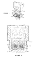
- Figure 1 is an isometric cutaway view of a channel induction furnace.
- Figure 2 is a vertical cross-sectional view of a channel induction furnace showing the channels within the refractory and the flow of molten metal through these channels.
- Figure 3 is an exploded isometric view of the channel core pattern, the transition pieces and the top throat mold used to form the cavities of the inductor block.
- Figure 4 is a cutaway isometric view of the inductor block in its mold with the channel core pattern, transition and top throat mold pieces all in place. The mold cores used to form the cavities for the inductor coils are shown removed.
- Figure 5 is a partially cutaway isometric view of the inductor block of the invention.
- Figure 6 is a partially cutaway isometric view of the cured refractory block mounted in the inductor casing. This view also shows the bottom and sidewall thermal insulation, the top refractory seal and the inductor coils wrapped around the laminated iron transformer core.
- Figure 7 is a flow sheet illustrating the process steps of the invention.
- Referring now particularly to Figures 1 and 2, a channel induction furnace is generally indicated at 2 comprising a detachable
upper hearth portion 6 and alower inductor portion 10.Inductor 10 includes acasing 60 having mounted therein refractory 20 havingchannels 30 therein through which molten aluminum flows as the secondary winding of a transformer or inductor. Aniron core 40 is threaded throughopenings inductor lining 20.Iron core 40 carriesprimary coils - In the operation of an induction furnace, current, applied to
primary coils 50 and 62, induces a current flow in the molten metal flowing throughchannels 30 which comprises the secondary coil of the transformer or inductor. The induced current in the molten metal secondary causes downward metal flow incentral channel 32, as shown in Figure 2. The metal flow then divides with approximately one half of the metal flowing throughchannel 36 back out into thehearth 6 with the remainder of the metal flowing throughchannel 38 to also enter thehearth portion 6 offurnace 2. It will be appreciated that the flow of molten metal through the channels, particularly at a sufficient velocity to prevent clogging of the channels with any oxide materials, as well as the indicated changes in direction of flow may cause erosion of the adjoining refractory walls, depending upon the type of refractory used and the sufficiency of curing or firing of the refractory. - As previously discussed, prior attempts at forming
refractory inductor block 20 by ramming in place a dry mix of refractory material around the iron core and a channel core pattern, such as wood which was then burned away, resulted in an incomplete firing of the refractory due to the need to maintain cooling adjacent the metal portions, such as either the iron core or the primary windings, during the firing of the refractory material. - Turning now to Figure 3, a
channel core pattern 80 is illustrated which, in accordance with one aspect of the invention, comprises a low melting material, such as a paraffin wax material, which may be used to formchannels 30 in the refractory inductor block of the invention.Core pattern 80 includes a large diametercentral portion 82 which will form thecentral channel 32 and reduceddiameter wing portions form channels channel core pattern 80. Preferably, however,channel core pattern 80 should be made of a material which can be removed by desolidifying, such as by volatilizing or decomposing or the like, without leaving any substantial residue upon exposure to heat rather than charring or burning as might be the case with materials, such as wood or some plastics. In any event, the material chosen will be one which will, upon its removal, leave a very smooth surface in the refractory inductor block channels to permit streamlined nonturbulent flow of the molten aluminum without providing ridges or discontinuities which may cause erosion and wear. - In a preferred embodiment, to make
channel core pattern 80 of low melting material, a wood pattern designed and constructed by the inductor manufacturer may be purchased and used to make a plaster split mold. This plaster mold is then used to form thechannel core pattern 80 made of low melting material, such as paraffin wax. Largediameter machine screws 96 are cast into the top portion of thecenter channel 82 and theside channels top mold block 120 as a template. These screws then properly locate and hold thetop mold block 120 andtransition members channel core pattern 80 during the refractory casting. - In accordance with the invention, the refractory mix used in forming the inductor block comprises a mixture of calcim aluminate, borosilicate frit and an aggregate selected from the group consisting of an alumina-bearing compound, a silica-bearinj compound and mixtures thereof. The mixture preferably consists essentially of 74.5 to 90%, and preferably 79.5 to 89.5 wt.X alumina, 9.5 to 25 wt.%, and preferably 10 to 20 wt.X calcium aluminate and 0.5 to 1.5 wt.X borosilicate frit.
- When alumina is utilized as the aggregate, it may be tabular alumina, and its particle size is preferably controlled such that 20 to 40 wt.% of the alumina particles are between 1.41 mm and 4.76 mm in size, 15 to 30 wt.% are between 0.297 mm and 1.41 mm in size, and 25 to 40 wt.X are less than 0.297 mm in size.
- When silica is used as the aggregate, it may be used in a particle size range of about -4 mesh (U.S. Standard). Preferably, the silica particle mixture contains about 50 wt.% particles of -10 to +325 mesh with the balance smaller. Most preferably, about 20 to 30 wt.% of the particles are -10 to +20 mesh, about 15 to 25 wt.% -20 to +100 mesh and the balance -100 mesh.
- The calcium aluminate which is used in the invention may be obtained from a variety of commercial sources. In a preferred embodiment of the invention, the calcium aluminate comprises a mixture of 75 to 83 wt.% aluminum oxide and 14 to 23 wt.% calcium oxide, with a total of no more than 3 wt.X of other oxides, primarily zinc oxide, boron oxide and silicon dioxide. Such a calcium aluminate product is sold by the Aluminum Company of America under the designation "CA-25". The particle size of the calcium aluminate is preferably controlled so that at least 90 wt.X is less than 0.044 mm.
- The borosilicate frit consists essentially of 15 to 35 wt.% boron oxide; 5 to 30 wt.% silicon dioxide; 10 to 60 wt.% of a metal selected from the class consisting of zinc oxide, lead oxide and calcium oxide; and a total of no more than 20 wt.% alkali compounds, such as lithium oxide, sodium oxide and potassium oxide. The preferred frit also contains 5 to 25 wt.% fluorine, and its particle size is controlled to less than 0.149 mm.
- To form the refractory inductor block of the invention, the
top throat mold 120, thetransition pieces channel core pattern 80 are all assembled and anchored upside down inmold 100, as shown in Figure 4. The coilcore mold pieces 110 are then placed inmold 100 and anchored to thesidewalls 104 ofmold 100. The refractory mix is then poured into the mold using a stick vibrator during the fill to make sure all air bubbles have been removed and that the fill is complete. - The refractory material is first cured for a period of from 6 to 10 hours at from about 21 to 32°C (70 to 90°F.) and then dried to remove physically absorbed water for from 20 to 30 hours at from 35 to 110°C (95 to 230°F).
Top mold block 120 andtransition pieces mold blocks 110 are removed through the sidewall ofcontainer mold 100. The greenrefractory inductor block 20 is then removed fromcontainer mold 100. The resulting greenrefractory inductor block 20 only containschannel core pattern 80 therein which may be melted out prior to the firing operation. - The green
refractory inductor block 20, as seen in Figure 5, in accordance with the invention, is now fired. The firing is carried out at a temperature of from about 760 to 871°C (1400 to 1600°F), preferably about 815.5°C (1500°F), for from 5 to 20 hours, preferably 6 hours. Most preferably, the firing is done at 815.5°C (1500°F) for 6 hours with a maximum temperature variation of + 2.78°C (5°F). The green refractory is brought up to the firing temperature slowly at a rate of about 5.6°C (10°F) climb per hour until the 815.5°C (1500°F) firing temperature is reached. After the firing time has elapsed, the furnace is shut off, and the firedrefractory inductor block 20 is allowed to cool, on its own in the closed furnace, back to ambient temperature. -
Refractory inductor block 20 is now ready for installation incasing 60, as shown in Figure 6. The bottomcastable insulation layer 72 is poured intocasing 60 to the proper depth (12 inches) and permitted to air dry and harden.Inductor block 20 is positioned in casing 60 oninsulation layer 72 and acastable insulation material 70, such as a calcium aluminate mixture, is poured intocasing 60 aroundrefractory inductor block 20 to holdblock 20 in place. Pouring the toprefractory seal 74 in place flush with the top ofinductor block 20 and the top flange of thecasing 60 completes the lining. It should be noted here thatinsulation materials insulation insulation refractory inductor block 20 in alignment withcasing 60 and provide thermal insulation for the whole system. - After
refractory inductor block 20 has been mounted incasing 60,iron core 40 withcoils openings block 20 and the corresponding openings incasing 60. -
Hearth member 6 is then secured toinductor 10, coils 50 and 52 connected to an external power source, and molten aluminum is poured intopreheated hearth 6 to enter thechannels 30 formed ininduction block 20 to form the secondary coil of the transformer or inductor. In accordance with the invention, the erosion or abrasion ofrefractory inductor block 20 by the flow of molten aluminum inchannels 30 will be substantially mitigated. - In a test conducted to determine the resistance to abrasion by molten aluminum of an inductor block formed in accordance with the invention, a refractory inductor block was cast from a mixture consisting essentially (in wt.%) of 80 to 85% alumina, 14 to 18% calcium aluminate and 0.5 to 1.5% of a borosilicate frit consisting essentially of about 21.5
% B 203, 12.2X F, 15.3% Na 20, 3.0% MgO, 0.7% A1203, 25.1% Si02 and 22.2% CaO. The dry refractory mixture was blended with an amount of water equal to about 5 to 8 wt.X of the dry mix weight. The mixture was cast around a wax channel core pattern and cured at 21 to 32°C for about 8 hours. The cured block was then dried to remove physically absorbed water for about 24 hours at 35 to 110°C. The channel core pattern was melted out by heating to 135°C. The block was then fired by raising the temperature in a shuttle kiln from ambient about 5.6°C (10°F) per hour up to 815.5°C (1500°F). The refractory was fired for 6 hours while maintaining this temperature + 2.78°C (+ 5°F). The block was allowed to cool back to room temperature. The resultant fired refractory inductor block was then mounted in a channel induction furnace, which was operated successfully for 225 days not limited by refractory life and far beyond that previously experienced with prior art lining types. - Thus, the invention provides an improved refractory inductor block and a method of making same wherein a refractory mix capable, after firing, of withstanding corrosion and erosion by contact with molten aluminum, is molded around a channel core pattern made from a material, such as wax, capable of desolidifying upon the application of heat. The green refractory block is heated to remove the channel core pattern and then further heated under carefully controlled conditions to uniformly fire the refractory to obtain the desired properties of corrosion and abrasion resistance to molten aluminum in finished refractory inductor block product.
whereby a fired refractory inductor block will be formed capable of withstanding deterioration from contact with molten aluminum.
Claims (10)
whereby a fired refractory inductor block (20) will be formed capable of withstanding deterioration from contact with molten aluminum.
Applications Claiming Priority (2)
| Application Number | Priority Date | Filing Date | Title |
|---|---|---|---|
| US67250684A | 1984-11-19 | 1984-11-19 | |
| US672506 | 1984-11-19 |
Publications (2)
| Publication Number | Publication Date |
|---|---|
| EP0182345A2 true EP0182345A2 (en) | 1986-05-28 |
| EP0182345A3 EP0182345A3 (en) | 1987-11-11 |
Family
ID=24698841
Family Applications (1)
| Application Number | Title | Priority Date | Filing Date |
|---|---|---|---|
| EP85114660A Withdrawn EP0182345A3 (en) | 1984-11-19 | 1985-11-18 | Improved channel inductor block for channel induction furnace and method of making same |
Country Status (5)
| Country | Link |
|---|---|
| EP (1) | EP0182345A3 (en) |
| JP (1) | JPS61173074A (en) |
| AU (1) | AU4998885A (en) |
| CA (1) | CA1263882A (en) |
| NO (1) | NO854531L (en) |
Cited By (2)
| Publication number | Priority date | Publication date | Assignee | Title |
|---|---|---|---|---|
| US20130075963A1 (en) * | 2010-03-29 | 2013-03-28 | Bluescope Steel Limited | Ceramic lined channel inductor |
| EP2371467A4 (en) * | 2008-12-30 | 2017-08-02 | GH Electrotermia, S.A. | Method for manufacturing inductors for induction heating using microfusion techniques |
Families Citing this family (1)
| Publication number | Priority date | Publication date | Assignee | Title |
|---|---|---|---|---|
| AP2013007140A0 (en) * | 2011-03-01 | 2013-09-30 | Louis Johannes Fourie | Channel type induction furnace |
Family Cites Families (6)
| Publication number | Priority date | Publication date | Assignee | Title |
|---|---|---|---|---|
| US1461863A (en) * | 1923-07-17 | Walter e | ||
| US3092682A (en) * | 1960-03-24 | 1963-06-04 | Ajax Magnethermic Corp | Submerged resistor type induction furnaces and methods and processes therefor |
| US4088502A (en) * | 1975-12-12 | 1978-05-09 | Aluminum Company Of America | Corrosion resistant castable refractory mix |
| DE2847483C2 (en) * | 1978-11-02 | 1982-12-02 | Fa. Adolf A. Fleischmann, 6000 Frankfurt | Process for the production of the monolithic channel lining of an induction channel melting furnace |
| US4348236A (en) * | 1980-09-09 | 1982-09-07 | Aluminum Company Of America | Composition for castable refractory block |
| SE8103473L (en) * | 1981-06-02 | 1982-12-03 | Hoeganaes Ab | LINING OF INDUCTIONS FOR HEATING AND MELTING OF METALS |
-
1985
- 1985-11-13 NO NO854531A patent/NO854531L/en unknown
- 1985-11-13 CA CA000495247A patent/CA1263882A/en not_active Expired
- 1985-11-18 AU AU49988/85A patent/AU4998885A/en not_active Abandoned
- 1985-11-18 EP EP85114660A patent/EP0182345A3/en not_active Withdrawn
- 1985-11-19 JP JP60259652A patent/JPS61173074A/en active Pending
Cited By (3)
| Publication number | Priority date | Publication date | Assignee | Title |
|---|---|---|---|---|
| EP2371467A4 (en) * | 2008-12-30 | 2017-08-02 | GH Electrotermia, S.A. | Method for manufacturing inductors for induction heating using microfusion techniques |
| US20130075963A1 (en) * | 2010-03-29 | 2013-03-28 | Bluescope Steel Limited | Ceramic lined channel inductor |
| US9429364B2 (en) * | 2010-03-29 | 2016-08-30 | Bluescope Steel Limited | Ceramic lined channel inductor |
Also Published As
| Publication number | Publication date |
|---|---|
| JPS61173074A (en) | 1986-08-04 |
| EP0182345A3 (en) | 1987-11-11 |
| NO854531L (en) | 1986-05-20 |
| AU4998885A (en) | 1986-05-29 |
| CA1263882A (en) | 1989-12-12 |
Similar Documents
| Publication | Publication Date | Title |
|---|---|---|
| CN107512918A (en) | A kind of preformed bricks of resource reusing | |
| EP0182345A2 (en) | Improved channel inductor block for channel induction furnace and method of making same | |
| US4106945A (en) | Investment material | |
| SU927103A3 (en) | Method for making prefabricated structure of metal production furnace wall | |
| AU683263B2 (en) | Device for feeding molten metal, particularly cast iron, to a casting machine, and casting installation incorporating same | |
| US20090114365A1 (en) | Material used to combat thermal expansion related defects in high temperature casting processes | |
| US8007580B2 (en) | Material used to combat thermal expansion related defects in high temperature casting processes | |
| CA1207124A (en) | Metal founding | |
| EP0069094A1 (en) | Lining of inductors for holding and melting of metals | |
| JPS645759Y2 (en) | ||
| Hammersmith et al. | Improved Channel Inductor Block for Channel Induction Furnace and Method of Making Same | |
| US20030011093A1 (en) | Method for production of an oxidation inhibiting titanium casting mould | |
| CN215279844U (en) | Parallel smelting and casting facility | |
| JP2004083361A (en) | Playable castable | |
| JPS645758Y2 (en) | ||
| JP3841185B2 (en) | Induction furnace | |
| JP3952222B2 (en) | Induction furnace | |
| SU1184840A1 (en) | Device for manufacturing fusion-cast refractories | |
| JPH0340319B2 (en) | ||
| JPS5845173A (en) | Lining material for dielectric melting furnace | |
| SU1002787A1 (en) | Induction furnace | |
| JP2676223B2 (en) | Refractory lining material removal method in crucible induction furnace | |
| SU1085669A1 (en) | Method of producing bimetal steel-cast iron castings | |
| SU944726A1 (en) | Mixture for producing casting moulds and cores | |
| KR810000447B1 (en) | Thermit compositions for ingot mould repair |
Legal Events
| Date | Code | Title | Description |
|---|---|---|---|
| PUAI | Public reference made under article 153(3) epc to a published international application that has entered the european phase |
Free format text: ORIGINAL CODE: 0009012 |
|
| AK | Designated contracting states |
Kind code of ref document: A2 Designated state(s): AT BE CH DE FR GB LI NL SE |
|
| PUAL | Search report despatched |
Free format text: ORIGINAL CODE: 0009013 |
|
| AK | Designated contracting states |
Kind code of ref document: A3 Designated state(s): AT BE CH DE FR GB LI NL SE |
|
| 17P | Request for examination filed |
Effective date: 19880505 |
|
| 17Q | First examination report despatched |
Effective date: 19890425 |
|
| STAA | Information on the status of an ep patent application or granted ep patent |
Free format text: STATUS: THE APPLICATION IS DEEMED TO BE WITHDRAWN |
|
| 18D | Application deemed to be withdrawn |
Effective date: 19900725 |
|
| RIN1 | Information on inventor provided before grant (corrected) |
Inventor name: ORMESHER, ROBERT J. Inventor name: HAMMERSMITH, VIRGINIA L. |