EP0182382A2 - Centralized control method for looms and device thereof - Google Patents
Centralized control method for looms and device thereof Download PDFInfo
- Publication number
- EP0182382A2 EP0182382A2 EP85114810A EP85114810A EP0182382A2 EP 0182382 A2 EP0182382 A2 EP 0182382A2 EP 85114810 A EP85114810 A EP 85114810A EP 85114810 A EP85114810 A EP 85114810A EP 0182382 A2 EP0182382 A2 EP 0182382A2
- Authority
- EP
- European Patent Office
- Prior art keywords
- looms
- host computer
- data
- loom
- control
- Prior art date
- Legal status (The legal status is an assumption and is not a legal conclusion. Google has not performed a legal analysis and makes no representation as to the accuracy of the status listed.)
- Withdrawn
Links
Images






Classifications
-
- G—PHYSICS
- G05—CONTROLLING; REGULATING
- G05B—CONTROL OR REGULATING SYSTEMS IN GENERAL; FUNCTIONAL ELEMENTS OF SUCH SYSTEMS; MONITORING OR TESTING ARRANGEMENTS FOR SUCH SYSTEMS OR ELEMENTS
- G05B19/00—Program-control systems
- G05B19/02—Program-control systems electric
- G05B19/04—Program control other than numerical control, i.e. in sequence controllers or logic controllers
- G05B19/042—Program control other than numerical control, i.e. in sequence controllers or logic controllers using digital processors
- G05B19/0421—Multiprocessor system
-
- D—TEXTILES; PAPER
- D03—WEAVING
- D03J—AUXILIARY WEAVING APPARATUS; WEAVERS' TOOLS; SHUTTLES
- D03J1/00—Auxiliary apparatus combined with or associated with looms
- D03J1/006—Controlling a group of looms
Definitions
- the present invention relates to a method for centralizing and controlling a plurality of looms, and more particularly to that for preparing weaving conditions by trial weaving, and storing, reading, and transferring control data bearing the weaving conditions after completing the preparation, and further means for changing contol data at need after the preparation.
- a monitoring system is known up to now as a system to connect many looms with a control computer.
- the monitoring system collects data of the rates of operations of respective looms and display them for every looms, but it does not directly control the respective looms.
- the respective looms require many control parameters such as a number of RPM of a prime motor of the loom, a number of beatings, tension of a warp yarn, on/off timing of each nozzle, and pressure of air for weft insertion, etc.
- many looms not one loom, from several tens to several hundreds thereof are operated. Moreover, they must often weave the same products. However, provided that the same many data are then set for every looms, working efficiency is lowered and requires much times to be needed.
- a centralized control system may be profitably employed, in which a host computer is placed on the center of the factory, and control paramenters previously stored in the computer are delivered to control units of respective looms only by entering a product number. Namely, with control parameters for every products stored and kept in the host central computer, a required control data in need can be immediately set to the control devices of the respective looms upon starting to weave any fabric.
- control data provided with symbols showing fabric specifications are previously registered for every kinds of fabrics, and a required control data is delivered to all the looms to permit the looms to be automatically set by designating a symbol showing a fabric specification.
- switch means for switching a plurality of looms between on-line and off-line operations are provided among control devices and terminals of the looms.
- a testing loom is switched off, for which the optimum control (weaving) condition is then evaluated while directly changing various weaving conditions, i.e., control parameters.
- the resultant optimum control condition is stored in a central host computer, and thereafter other remaining looms are operated based on the estimated optimum control condition.
- a centralized control system peculiar to the looms can be achieved.
- Another object of the present invention is to provide a centralized control method capable of effectively operating a plurality of looms even if characteristics peculiar to the respective looms are varied.
- standard control data for controlling looms and contents thereof i.e., peculiear style numbers representative of fabric specifications are previously stored in a memory of a host computer.
- There standard control data are corrected in response to variations of characteristics of the respective looms.
- the corrected peculiar control data are made to include loom numbers besides style numbers, and stored.
- the host computer as a control data having a certain style number is designated besides the presence of the above control data in a retrieval process, and transmits the control data peculiar to the loom to the loom instead of delivering a standard control data if there is the above control data with the loom number.
- the host computer transmits control data taken in consideration of the variations, even if present, of the characteristics of the looms to the looms.
- control data taken in consideration of the variations, even if present, of the characteristics of the looms to the looms.
- Still another object of the present invention is to provide a centralized control method for looms and a device thereof capable of eliminating a trial weaving process requiring much labor and time and improving production efficiency.
- past accumulation data are stored beforehand in a memory connected with a host computer serving to control a plurality of looms.
- the host computer executes prescribed arithmetic operation or interpolation operation to evaluate standard set values for loom control.
- past accumulation data are stored beforehand in a memory connected with a host computer serving as a plurality of looms.
- the host computer executes prescribed arithmetic operation or interpolation operation to evaluate standard set values for loom control, successively compares various operation data available from the looms starting to be operated by operation signals based on the above standard set values with a plurality of reference values entered therein and previously put in the order of priority to subject the looms to the optimal control, and corrects the above standard set values based on the compared results.
- the host computer automatically evaluates respective standard set values from past enormous actually resulting data by entering the fabric specifications therein, and then respectively delivers the standard set values to corresponding looms to effect centralized control. Accordingly, a trial weaving process can be eliminated to improve production efficiency.
- the evaluated standard set values are self-corrected to provide the optimum operation of the looms.
- the looms rapidly respond in the optimum conditions to frequent changes of kinds of fabrics including unknown fabrics due to many kinds of fabrics but with a small quantities of production.
- a first embodiment according to the present invention will be described below, which corresponds to the first object of the present invention and relates to a method of preparing the optimal weaving condition by trial weaving.
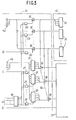
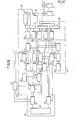
- a centralized control apparatus 1 for looms being a main constituent of the- present invention has a central host computer 2 connected with many looms 3 via a bidirectional data bus 4.
- the host computer 2 includes a display 6 connected bidirectionally to a CPU 5, an input keyboard 7, a printer 8 for recording, an external memory 9, and a terminal control unit 10.
- each of the looms 3 has therein a terminal device 13 connected with the terminal control unit 10, a setting unit 12 connected with the terminal device 13, and a control unit 11 connectable with the terminal device 13 and setting unit 12 via an on/off line switch 14.
- Fig. 3 shows the interiors of the setting unit 12 and the terminal device 13.
- the setting unit 12 for example, if an air jet loom, has a plurality of setting units 15 for setting a number of RPM of a prime mover motor, a number of times of yarn beatings, warp yarn tension, on/off timing of each nozzle, and air pressure for weft insertion, etc.
- These setting units are connected with an input data bus 4a via interfaces 1 6 in the terminal device 13.
- an output data bus 4b is connected with latches 17 having numbers corresponding to those of the setting units 15.
- the control unit 11 can be connected with both the setting units 15 and the latches 17 corresponding therreto by the switch 14, i.e., gang switches 18 for switching on-and off/off line states of the setting unit 12 and the terminal device 13.
- a data selection signal A is provided to a common one side of input terminals of AND gates 20, 21 via decoder 19.
- the AND gates 20 are connected with the interfaces 16 on the comon output side of the gates, while the AND gates 21 connected with control input terminals of the latches 17 on the output sides of the gates 21.
- a read command signal B is entered into the other input terminals of the AND gates 20, while a data setting command signal C in the other input terminals of the AND gates 21.
- a operation prohibiting signal D is directly entered from the host computer 2 into the control unit 11 via the terminal device 13 at need.
- the switch 14 (gang switches 18) of the loom 3 for trial weaving is set to an off-line state, and the respective setting units 15 of the setting unit 12 are connected with the control unit 11 of the loom.
- the respective setting units 15 are operated to set the control conditions i.e., the control data such as a number of RPM of the prime mover motor required for weaving, a number of time of beatings, warp yarn tension, on/off timing of each nozzle and air pressure for weft insertion.
- trial weaving is repeated on the basis of the respective data until a product with an intended quality is yielded.
- the switch 14 is switched to an on-line state, whereby the control unit 11 is connected with the latches 17.
- the optimal control data is read out of the external memory 9 and stored in the respective latches 17 of the loom 3 via the output data bus 4b based on the data setting command signal C in succession by the data selection signal A.
- the control unit 11 incorporates therein the optimal control condition data from the latches 17, whereby control the corresponding loom 3 under the optimal control conditions.
- the optimal control data can be supplied from the external memory 9 to other looms 3.
- the host computer 2 checks numbers of stop times of the respective looms 3, and issues an operation prohibiting signal D to the loom 3 when the number of the stop times thereof is over a prescribed value to stop the loom 3, and alarms.
- the loom 3 is switched to an off-line state, and control parameters are adjusted by the setting unit 12, and thereafter stored in the host computer 2 as specific data peculiar to the loom 3 for the number of woven at that time.
- the host computer 2 enters the specific conditions in the control unit 11 instead of the standard data.
- This function allows the variations among the looms 3 to be limited to the minimum at the time of corrective operation thereof, and increases productivity of fabrics in a factory.
- the bidirectional bus 4 may be constructed only with one transmission line for serial transmission.
- the embodiment corresponds to the second object of the present invention, and relates to storage, read, and transfer of the optimal control data after the trial weaving.
- the memory 9 in the host computer 2 has stored average or standard control data such as a number of RPM of each loom 3, a number of yarn beatings, and warp yarn tension, etc. These control data are stored together with peculicar style number representative of fabric specifications.
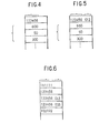
- Fig. 4 shows an example of the standard control data, in which the style number is represented as "123456", for example.
- a number of RPM "600”, a number of beatings "50”, and warp yarn tension "300”, etc. provide control data as target values of weaving control for looms.
- the memory 9 included in the host computer 2 stores, besides standard control datga each having certain style number as shown in Fig. 4, control data which are corrected in consideration of variations of the characteristices of the respective looms 3 corresponding to the style numbers, and which are provided with the style numbers and the respective loom numbers (machine numbers).
- Fig. 5 shows an example of control data after corrected.
- a target value of a number of RPM has been herfe corrected from the standard number of RPM "600" to a peculiar value "550".
- the corrected control data has the style number "123456" affixed with, e.g., a loom number "012" at, e.g., the final end of the.style number, whereby the control data is distinguishable from standard control data.
- Fig. 6 shows a list of style numbers. Many style nubmers are employed in responce to fabrfic specifications. Standard control data are corrected in responce to variations of characteristics of the respective looms 3, each of which has, for example, a three-digit loom number "012" or "055" inserted at the final end thereof.
- the standard control data is corrected to provide that peculiar to each loom 3 by a method wherein a control data corresponding to a style number in interest registered in the host computer corrects the control data, an optionally selected loom is numbered in the control datawhich is then rfegistered as a control data after the correction, or based on first embodiment , a certain loom 3 is made the off-line state, and operating the loom 3 actually, the optimal value of control data is estimated while changing the control data, and thereafter the loom is returned to the on-line state and the changed control data is read in the host computer 2 in which control data of a fabrfic in interest and a loom are then numbered and registered.
- Fig. 7 shows a procedure for operating the host compute 2 in embodying the method according to the present invention.
- Step 1 a number of a loom intended to be supplied with a control data, e.g., "12" is entered in the host computer 2 after starting the program, and then in Step 2, a style number representative of the control data, e.g., "123456" is entered, and successively in Step 3, a style number list as shown in Fig. 4 is read in.
- Step 2 the presence of a data is decided which has the loom number "012" entered in Step 1 in the style number entered in Step 2, and if present, the operation advances to Step 5.
- step 5 it the style number with the loom number is of, for example, "123456012", the CPU 5 reads therein control data after corrected as shown in Fig. 4.
- Step 4 the operation branches to Step 6, in which the host compute 2 reads in a control data having the concerning style number, i.e., a style number shown in Fig. 6 "123456". Data contents as this time is of the standard control data as shown in Fig. 4.
- Step 7 the control data read in the host compute 2 in Step 5 or 6 is transferred to the loom 3.
- Step 7 the control data read in the host compute 2 in Step 5 or 6 is transferred to the loom 3.
- control data peculiar to the loom 3 is transmitted to the loom 3 which can weave a fabric under the optimal condition based on the control data transmitted thereto.
- control datga peculiar to a loom which can be not operated satisfactorily with the standard control data due to variations of the characteristics of the looms produced thereamong is automatically transferred and set to the loom besides the standard control data. Accordingly, with the present invention, flexible centralized control is made possible without deteriorating the rates of operations of a plurality of looms even if therfe are variations in characteristics of the individual looms.
- This embodiment corresponds to the third object of the present invention, and concerns in particular a method for quickly preparing new control data for new fabric specifications such for example as a warp yarn total number, a number of weft yarn beating times, yarn kinds, thickness, and weaving conditions, and concerns a device thereof.
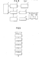
- Fig. 8 illustrates the first centralized control apparatus 1 as a functionnal block in relation to the present embodiment.
- the host computer 2 serves as a center for centralizing and controlling a plurality of looms 3.
- the host computer 2 has the same functions as those of set value evaluation means 23, a set value memory 24, and set value change means 27.
- a keyboard 7 and a display 6 such as a CRT constitutes fabric specification input means 28 for entering fabric specifications.
- accumulation data memory 22 such as a floppy disk is connected as an external memory 9 with the host computer 2.
- the plurality of the looms 3, being control targets constitute a terminal control unit 10 as a communication interface having a bidirectinal data bus 4, set value transmitting means 25, and operation data receiving means 26.
- Fig. 9 shows a procedure for entering the fabraic specifications in the computer.
- Fabric specification data such as kinds of warp yarns, thickness of a warp yarn, a warp yarn total number, kinds of weft yarns, weft yarn density, and weaving width are entered in succession.
- the host computer 2 evaluates a standard set value from past accumulation data stored in the accumulation memory. Further, basic data and similar data yielded based on past trial weaving and results available from actual weaving are assumed to be previously stored.
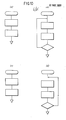
- Flowcharts illustrating the evaluation of the standard set values executed by the host computer 2 are shown in Fig. 10, while functional blocks corresponding to the flowcharts shown in Fig. 11.
- Figs. 10 (a) and 11 (a) are respectively of the flowchart and the functionnal block for evaluating the standard warp yarn total tension of value T.
- Figs. 10 (b) and 11 (b) are respectively of the flowchart and the functionnal block for evaluating a standard pressure (fluid pressure) sedt value P.
- a plurality of relationships between weft yarn thicknesses b 1 , b 2 , ... and fluid pressures P1, P 2 , ... as past similar data of the same kind as that of weft yarns entered from the keyboard 7 are read out from the accumulation data memory 22 as shown in Fig. 12.
- parameters b i , b i+1 , P i , P i+1 satisfying a relation b i ⁇ b ⁇ b i+1 for the weft yarn thicknesses entered from the keyboard 7 are estimated.
- Figs. 10 (c) and 11 (c) are of respectively the flowchart and the functional block for evaluating a number-of-RPM set value R.
- Figs. 10 (d) and 11 (d) are of respectively the flowchart and the functional block for evaluating an on/off timing set value "t" of a nozzle. Also for these cases, using similar data read from the accumulation data memory 22, interpolation operation is executed to evaluate the respective set values. All the standard set values of various kinds so evaluated are successively transmitted to designated relevant looms 3 as standard set values via the terminal control unit 10 as a communication interface and the bidirectional data bus 4.
- Fig. 14 shows a flowchart for illustrating an evaluation process of a number of the contral conditions in the order of Steps 1 to 10, in which any step number is shown in a parenthesis.
- Step 3 a decision process for deciding if the same specifications existed in the past is included in Step 3.
- the respetive looms 3 After receiving an operation signal, weaves based on the standard set value.
- Data associated with respective allowable upper and lower limit reference values of for example (1) the rate of operation, (2) a number of RPM, (3) warp yarn total tension, and (4) fluid pressure are entered through the keyboard after they are put beforehand in the order of priority as optional control reference values.
- the upper reference value of the rate of operation put in the first order of priority may be not entered.
- the respetive looms 3 terminal device 13 starting to be opertated in accordance with the respective standard set values feed back operation data via the bidirectional data bus 4 and the terminal control unit 10 as the communication interface to the host compouter 2.
- the host computer 2 compares in succession the opeation data fed back from the loom 3 with a plurality of the optimal control reference values entered in the order of priority, and corrects the respective standard set values on the basis of the comparison. Such operation is effected by the set value change means 27 and the set value memory 24 included in the host computer 2.
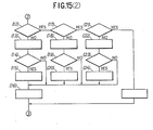
- Figs. 15 (1), (2) are flowcharts showing exemplary operations of the looms in the optimal control. The operation in conformity with the flow of the flowchart is effected at a prescribed period.
- Step 1 the operation is advanced such that a set value of the warp yarn total tension is reduced within a range wherein the set value is less than the lower limit of the warp yarn total tension which is then in the third order of priority (Steps 3 to 7).
- the set value of the number of RPM is reduced within a range wherein the set value is not less than the lower limit of the number of RPM being the second order of priority (Steps 8 to 11).
- the number of RPM, the second order of priority is lowered within a range it is not less than the lower limit thereof (Steps 21 to 24, and 16).
- Step 1 when the rate of operation is very high, i.e., in case of "YES" in step 1, the number of RPM and the warp yarn tension are increased within a range wherein the rate of operation is not less than the lower limit of the reference value (Steps 25 to 33), and if there is nevertheless no problem, the set value of the fluid (air) pressure is reduced (Steps 35 to 37 and 29). Moreover, in Steps 30 to 33, whether the upper limit value is made to be the optimal one or the lower limit value to be the optimal one is previously entered in the host computer along with the reference values. Here, high tension is made optimum.
- Fig. 16 is a block diagram showing an example of a centralized control apparatus according to the present invention.
- the fabric specification input means 28 has the key board 17, the display 6, a fabric specification input circuit 29 for entering fabric specification data from the keyboard 7, a machine number input circuit 30 for entering a loom number, and a fabric specification memory 31 for storing a fabric specification data.
- the accumulation data memory 22 includes a similar item/interpolation data memory 32, a data read circuit 33 for reading data abailable from the above latter memory 32, a data write circuit 34 for writing a data, a data memory 35 for storing arithmetic operation basic data such for example as tension/denier, and a write circuit 36 for writing basic data in the memory 35.
- the set value evaluation means 23 has a coincidence circuit 37 for deciding whether any same specification standard set value exists in the accumulation data memory 22 based on the data from the fabric specificaiton memory 31, a memory 38 for storing arithmetic operation items, a memory 39 for storing similar interpolation items, an evaluation method selection circuit 40 for selecting a proper evaluation method based on data from the above respective memorys 38, 39 and data from the fabric specification memory 31, an arithmetic ciucuit 41 for operating prescribed arithmetic operation on the basis of a signal from the selection circuit 40, a smilarity decision circuit 42, a similar data memory 43 for storing similar data derived from the similarity decision circuit 42, and an interpolation arithmetic circuit 44 based on a signal from the similarity data available from the similarity data memory 43.
- the set value memory 24 comprises various memories for storing data associated with fabric specifications, loom numbers, and respective standard set values evaluated in the arithmetic circuit 41 and the interpolation operation circuit 44.
- the set value transmitting means 25 has a scanning signal generator 45, a loom number transmitting circuit 46, a set value transmitting circuit 47 for transmitting the respective standard set values stored in the set value memory 24, and an output channel 8 connected with the bidirectional data bus 4, and standard set values transmitted therefrom are received by the terminal unit 13 for transmission/reception located on the loom side.
- the operation data receiving means 26 comprises an input channel 49 and an operation data input circuit 50 for inputting operation data from the looms 3 via the input channel 49 and the bidirectional data bus 4.
- the set value change means 27 comprises a decision standard input circuit 51 for entering a decision standard value from the fabirc specification input means 28, a decision reference memory 52 for storing the above decision reference value, an operation quality decidsion circuit 53 for receiving a reference value and an operation data and thereby deciding operation quality, and a set value correction circuit 54 for correcting the respective standard set values stored in the set value memory 24 based on the decision result available from the above operation quality decision circuit 53.
- the respective corrected standard set values are stored in the accumulation data memory 22 as fabric specification standard set values corresponding thereto on the basis of the decision result by the operation quality decision circuit 53.
- the accumulation data memory 22 is supposed to be an external memory such as a floppy disk, it may be one profitably employing a semiconductor memory such as a battery-backed-up random access memory (RAM) contained in the host computer.
- a semiconductor memory such as a battery-backed-up random access memory (RAM) contained in the host computer.
- a fourth embodiment will be described, wherein a method is given which enables data on a newly woven fabric to be automatically transferred to the control units of respective looms and therby control data for the next woven fabric to be set although now in weaving.
- control data in responce to kinds of fabircs are stored beforehand in the memory 9 of the centralized control apparatus 1, and a style number scheduled for the next weaving is made to wait as a queue for every looms.
- control data for the next woven fabirc are read in order based on warp-out signals from the respective looms 3, and transferred to the control units 11 of the respective looms 3, whereby the corresponding looms 3 are continuously operated.
- Control data for the succeeding woven fabrics are previously stored in the memory 9 as the queue, in such a manner. Accordingly, preparing works for the respective looms 3 can be effectively conducted without the need of data input each time of weavings.
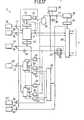
- Fig. 17 shows the arrangement of the host computer 2 for putting the present embodiment into practice.
- a control parameter setting unit 55 is connected with the memory 9 via a gate 56 for determining values of weaving conditions.
- a style number setting unit 57 is connected with the momory 9 via a gate 58 and a upper decoder 59 for setting a style number representative of a group of weaving conditions in responce to kinds of fabrics.
- a setting unit 60 for setting style numbers on and after the next weaving time is connected with an upper docoder 59 via a plurality of queue registers 8 1 ... 8 n corresponding to the respective loom numbers and a gate 62.
- a loom number setting unit 63 is connected with a common latch input terminal of the respective queue registers 8 1 ...8 n via a gate 64 and a loom number decoder 65, and futher via one of input terminals of a plurality of AND gates 66.
- a set pulse generator 67 is connected with the other of input terminals of an AND gate 69 via a gate 68.
- a set pulse generator 70 is connected directly with the memory 9 via a gate 71 while it branches through the gate 71 and is connected with the memory 9 via one of input terminals of an OR gate 72 through an address updating counter 73 and a lower decoder 74.
- a reference pulse generator 96 is connected with the other of the inpt terminals of the OR gate 72 via a gate 75 and a read pulse train generator 76, while it branches on this side of the gate 75 to a gate 77, a scanning counter 78, and a decoder and is connected with a multiplexer 80.
- the reference pulse generator 96 further branches and is connected with the loom number decoder 65 via a gate 82.
- the pulse train generator 76 is also connected in the other output terminal with clear input terminals of the queue registers 81...8n and a reset input terminal of a flip-flop 84 via a plurality of AND gates 83.
- the multiplexer 80 is connected with a set input ternimal of the flip-flop 84.
- One input terminal of the flip-flop is connected with a gate 82, while the other output terminal connected with respective one-side input terminals of a gate 75 and an AND gate, and with the gate 77 through a NOT gate 86 and with the gates 56, 58, 61, 68, 64, 71 through a NOT gate 87.
- Fig. 18 shows internal arrangement of the terminal device 13 which has plurality of latches 88 and a decoder 89.
- the plurality of the latches 88 store data such as a number of RPM of a loom prime motor and a number of times of yarn beatings, or warp yarn tension via a waveform shaper 90 and deliver them to a loom control circuit 91.
- the decoder 89 receives a selection item code from the waveform shaper 92 and operates the latch 88 corresponding to the code.
- a warp-out contact 93 of the loom control circit 91 is connected with the multiplexer 80 via a NOT gate 94 and an amplifier 95.
- the gate 82 remains opened due to the one output of the flip-flop 84 and the gates 56, 58, 61, 68, 64, 71, 77 remain opened because of the NOT gates 86, 87 due to the other output of the flip-flop 84.
- a style number selects upper addresses in the memory 9 via the upper decoder 59 by the style number setting unit 57 in order to set weaving conditions of a certain fabric.
- control parameters such as a number of RPM of the prime motor, a number of times of yarn beatings, and warp yarn tension are successively stored in the memory 9 based on memory timing pulses issued from set pluse generator 70 in order to set the control parameters, i.e., weaving conditions.
- a memory address in this case is determined without ambiguity by an upper address defined by the style number and a lower address defined by the counter 73 via the lower decoder 74.
- the lower address can be updated by the counter 73 and the lower decoder 74.
- the memory stores control parameters for every style numbers carried thereon.
- the succeeding style numbers are stored in the queue registers 8 1 ...8 n corresponding thereto via the setting unit 60 synchronized with the successive set pulses from the set pulse generator 67.
- the above operation for specifying the queue registers 8 1 ...8 n is performed by the loom number setting unit 63 and the loom number decoder 65.
- next style number is previously stored in the queue registers 8 1 ...8 n ⁇
- the flip-flop 84 changes to a set state and scanning effected by the loom number decoder 65 is stopped.
- the gates 56, 58, 61, 68, 64, 71, 77 are set to a closed state, while the gate 75 is opened.
- an output pulse from the reference pulse generator 96 is provided to the read pulse train generator 76.
- the corresponding gate 62 is opened by a signal from the loom number decoder 65. Then, the upper decoder 59 of the memory 9 receives the next style number concerning the loom 3 in the warp-out state from the queue registers 8 1 ...8 n corresponding to the warp-out loom 3, and a control parameter having the above style number is transferred to the corresponding loom 3 via the multiplexer 80. As described above, provided that the warp-out signal concerning a certain loom 3 is produced, the host computer 2 reads out the next style number from the corresponding queue registers 81...8n and automatically transfers a control parameter corresponding to the above style number via the multiplexer 80. Accordingly, in the warp-out state, the next preparation for weaving can be automatically effected without requiring new designation of the style number.
- the queue registers 8 1 ...8 n are provided for storing the next style number
- a further long queue may be formed with use of a microprocessor to store many style numbers.
- style numbers on and after the next time can be stored to further improve system performance.
- the embodiment provides a method for realizing the optimal control for looms in which control data for weaving required for actual operation of respective looms can be simply transferred from a central control unit to control units of the respective looms while yarn information can be also delivered to the control units of the respective looms.
- control data for weaving for every fabric styles are previously stored in the memory 9 of the host computer 2 in correspondence with 9 style number, and upon changing the fabirc style of each loom the style number is designated, whereby all the control data required for the weaving can be read out of the memory 9 and immediately transmitted for every control units 11 of the corresponding looms 3.
- information of yarns needed for the weaving in silk reeling processes thereof is also stored simultaneously with that of beam numbers and lot numbers, and upon changing warp yarn beams and weft yarn cones information thereof is entered in the carbonl device 11 of the loom 3.
- the present invention can realize the optimal operation state for every looms 3 in response to the yarn information.
- the host computer 2 incorporates therein control data required for the control units 11 of the respective looms 3 by a control program based on control, arithmetic operation, and memory functions of the CPU 5, and stores them in the memory 9.
- the host computer 2 further transfers required control data through the data bus 4 on the basis of a request from the control device 11 of each loom 3.
- Such control data are entered in the host computer 2 via the keyboard 7 and prepared while checking them with the display 6, and thereafter stored in the memory 9 together with a style number peculiar to a fabric style.
- weaving condition data such for example as a number of RPM of a loom per unit time is for example an air jet loom, a number of times of weft beatings per unit length, warp tension in weaving, on/off timing of a nozzle for weft insertion, pressure setting of air for weft insertion, and others are prepared beforehand for every style numbers, i.e., for every fabric styles, and thereafter stored in the memory 9.
- designation of any control data thereafter can be simply effected only by specifying a style number in interest.
- contents of the control data so set can be changed at need, and in order to realize the optimal conditions can be altered each time of actual weaving or trial weaving.
- Fig. 19 shows a procedure in changing internal control data for every style numbers.
- style change by an operator through the keyboard 7, a program needed to change a fabric style is automatically started.
- the CPU 5 reads out the designated style number from the memory 9 and displays it on the display 6.
- an operator selects an item to be changed from the above control data and changes its numerical value to a needed one.
- the CPU 5 newly stores in the memory 9 the changes control data as style number data.
- yarn information is stored in the memory 9 together with a warp yarn beam number and a weft yarn cone lot number.
- Warp yarn information is representative of the total length of a yarn, a beam outer diameter or bad yarn information such as fluffing, siges, unevenness, yarn break in a pre-process, e.g., in a sizing process.
- weft yarn information is representation of, besides bad yarn information such as yarn break in yarn manufacture, i.e., a yarn lot, yarn length, and yarn thickness.
- the host computer 2 stores style numbers each for specifying control data, beam numbers each for specifying warp yarn information, and lot numbers for specifying weft yarn information as a queue for every loom numbers as a series of starting data, in the external memory 9 of the CPU 5.
- Fig. 20 shows the order of operation by a centralized control apparatus of the present embodiment.
- the centralized control is executed by a centralized control program contained in the CPU 5.
- the CPU 5 upon receiving a command of starting the centralized control, starts its control, designates a loom number, e.g., "1", and receives weaving information data from the terminal unit 13 of the loom 3 control device 11.
- the terminal unit 13 provides data needed to control the corresponding loom and delivered from the host computer 2 to the loom control device 11, while incorporates a signal representative of weaving information from the corresponding loom, temporarily stores the signal, and transfers it to the host computer 2 at the time of receiving a data transfer command from the host computer 2.
- the CPU 5 decides here the presence of a data request by the control device 11 of the loom 3 based on the above reception data.
- the control device 11 requests any data
- the CPU 5 desgnates the style number of the data, a warp yarn beam number, and a weft yarn let number, whereby reads out control data and yarn information corresponding to the above numbers, and transfers them to the corresponding terminal device 13 through the terminal control unit 10 and the data bus 4.
- the terminal device 13 here temporarily the transferred control data and yarn information data, and transmits them to the control unit 11 of the corresponding loom 3 which then holds the above data as required for loom operation to conduct necessary control based on the above data.
- yarn information, particularly bad yarn data are profitably employed to temporarily set a speed of loom revolutions to lower value in the vicinity of a bad portion of the yarn.
- the CPU 5 reads the next loom number, e.g., "2", and conducts the same processing as before therefor.
- the CPU 5 branches from a data transfer routine, enters a registering routine, and decides the presence of style registering, beam registering, and lot number registering, in order.
- the host computer 2 stores the control data for each style number.
- an operator enters first a loom number, then a style number, and finally a beam number corresponding to the style number, yarn information thereof, a cone number corresponding to the style number, and weft yarn information thereof. Futhermore, the operator stores the above information in the external memory 9, while registers the style number and beam number, and a lot number in the external memory 9 as starting data of the corresponding loom.
- the host computer 2 enters the loom number and style number corresponding thereto, the beam number, and lot number as starting data for all the looms 3, and registers them therein.
- Fig. 21 shows other form of the centralized control described above.
- the CPU 5 after starting the centralized control, decides the presence of a control data transfer request from the control unit 11 of the loom 3. For example, when there is a transfer request from the control unit 11 of the loom 3, the CPU 5 starts a data transfer routine. In the first place, the CPU 5 decides whether the data for which transfer is req.uested in control data for a style or not, and if no, advances forward the next step to transfer needed yarn information. But, when control data are requested because of the need of style change, the CPU 5 searches a number of the next starting style, reads needed control data from the above number and transfers it, and thereafter transfers yarn information of a warp yarn beam number and a weft yarn lot number to the control unit 11 of the loom 3. Such operation is repeated also for the other control unit 11, whereby the host computer 2 controls the control unit 11 of all the looms.
- the CPU 5 When there is no data transfer request at the above decision of the presence of the control data transfer request, the CPU 5 enters a registering routine and decides the presence of style registering, yarn informaion registering, and transfer order registering from an operator.
- a style registering command is provided to the CPU 5 to permit an operator to newly enter control data corresponding to a style number, a step of style registering is started. The operator, after registering or style number, enters in succession, control data corresponding to the above style number. Thus, all the control data are registered. At the time of end of such style registering, the control program again returns to the first step.
- the CPU 5 starts this program.
- the operator after registering a beam number and a lot number, enters in sucession yarn information of warp and weft yarns.
- the control program again returns to the first step after all the needed information is enterd.
- the centralized control apparatus 1 When the operator requests registering of the transfer order, the centralized control apparatus 1 starts its steps. Then, the operator, after specifying the loom number, designates the transfer order based on the weaving order of the associated loom and simultanelusly enters the style number. The operator further enters in succession a corresponding beam number and lot number. In such manner, when a style number to be weaved, a warp yarn beam number and a weft yarn cone lot number at that time, etc., are specified for a control unit 11 of a certain loom 3, the transfer order is provided and entered. Accordingly, in the present program, various data can be entered even if it is not specified to which loom 3, a warp yarn beam, and a weft yarn cone should be supplied. This is advantageous to prepare starting data when the above information is specified.
Landscapes
- Engineering & Computer Science (AREA)
- Physics & Mathematics (AREA)
- General Physics & Mathematics (AREA)
- Automation & Control Theory (AREA)
- Textile Engineering (AREA)
- Looms (AREA)
Abstract
Description
- The present invention relates to a method for centralizing and controlling a plurality of looms, and more particularly to that for preparing weaving conditions by trial weaving, and storing, reading, and transferring control data bearing the weaving conditions after completing the preparation, and further means for changing contol data at need after the preparation.
- A monitoring system is known up to now as a system to connect many looms with a control computer. The monitoring system collects data of the rates of operations of respective looms and display them for every looms, but it does not directly control the respective looms.
- By contrast, upon actually operating looms, for example, air jet looms, the respective looms require many control parameters such as a number of RPM of a prime motor of the loom, a number of beatings, tension of a warp yarn, on/off timing of each nozzle, and pressure of air for weft insertion, etc. In an ordinarly weaving factory, many looms, not one loom, from several tens to several hundreds thereof are operated. Moreover, they must often weave the same products. However, provided that the same many data are then set for every looms, working efficiency is lowered and requires much times to be needed.
- So, a centralized control system may be profitably employed, in which a host computer is placed on the center of the factory, and control paramenters previously stored in the computer are delivered to control units of respective looms only by entering a product number. Namely, with control parameters for every products stored and kept in the host central computer, a required control data in need can be immediately set to the control devices of the respective looms upon starting to weave any fabric.
- Then, the recent textile weaving industry intends to obtain highly value-added fabrics, and thus development for yielding new products has been increasing needed. In such a developmental process, the optimum weaving conditions must be determined ordinarily with use of one loom as a trial one while changing control conditions of looms. In the instance, a general-purpose centralized control system as described above may lower rather than raise efficiency of the trial weaving.
- In addition, another centralized control device for looms is conventionally known in which control data provided with symbols showing fabric specifications (a number of RPM of a prime motor of a loom, number of beatings, warp tension, and weaving density) are previously registered for every kinds of fabrics, and a required control data is delivered to all the looms to permit the looms to be automatically set by designating a symbol showing a fabric specification.
- In such prior devices, a data to be registered is in general an average one commonly usable for all the looms. Accordingly, provided that individual looms change in inherent characteristics thereof, the looms can not be operated respectively as desired with the average registered data. Prior arts suffer from these problems.
- In addition, in the prior weaving techniques, upon weaving a new fabric, only a single loom is opeated as a testing machine to estimate the optimum control condition while changing for trial weaving many control parameters such for example as a number of RPM of a prime power mover motor of a loom, a number of beatings, warp yarn tensions, on/off timing of each nozzle for weft insertion, etc. In such trial weaving, an operator first provides certain condition to a loom based on his past experiences and perception, starts weaving, evaluates the results in succession, to estimate the optimum condition with trial and error.
- However, such a technique requires much labor and time, as well as a great deal of skill. This is a serious obstacle in quickly supplying woven fabrics to markets based on new specifications since the markets have been recently diversified in demand.
- It is an object of the present invention to provide a method of briefly estimating the optimum control condition on a trial loom in trial weaving and operating other all looms with a centralized control system based on the estimated optimum control condition.
- According to the present invention, switch means for switching a plurality of looms between on-line and off-line operations are provided among control devices and terminals of the looms. In trial weaving, a testing loom is switched off, for which the optimum control (weaving) condition is then evaluated while directly changing various weaving conditions, i.e., control parameters. The resultant optimum control condition is stored in a central host computer, and thereafter other remaining looms are operated based on the estimated optimum control condition. Thus, a centralized control system peculiar to the looms can be achieved.
- Another object of the present invention is to provide a centralized control method capable of effectively operating a plurality of looms even if characteristics peculiar to the respective looms are varied.
- According to the present invention, standard control data for controlling looms and contents thereof, i.e., peculiear style numbers representative of fabric specifications are previously stored in a memory of a host computer. There standard control data are corrected in response to variations of characteristics of the respective looms. The corrected peculiar control data are made to include loom numbers besides style numbers, and stored. The host computer, as a control data having a certain style number is designated besides the presence of the above control data in a retrieval process, and transmits the control data peculiar to the loom to the loom instead of delivering a standard control data if there is the above control data with the loom number.
- With such a method, the host computer transmits control data taken in consideration of the variations, even if present, of the characteristics of the looms to the looms. Thus, flexible and effective centralized control can be achieved.
- Still another object of the present invention is to provide a centralized control method for looms and a device thereof capable of eliminating a trial weaving process requiring much labor and time and improving production efficiency.
- Thus, according to the first method of the present invention, past accumulation data are stored beforehand in a memory connected with a host computer serving to control a plurality of looms. With use of fabric specifications entered in the host computer and the past accumulation data read out of the memory, the host computer executes prescribed arithmetic operation or interpolation operation to evaluate standard set values for loom control.
- Moreover, according to the second method of the present invention, past accumulation data are stored beforehand in a memory connected with a host computer serving as a plurality of looms. With use of fabric specifications entered in the host computer and the past accumulation data read out of the memory, the host computer executes prescribed arithmetic operation or interpolation operation to evaluate standard set values for loom control, successively compares various operation data available from the looms starting to be operated by operation signals based on the above standard set values with a plurality of reference values entered therein and previously put in the order of priority to subject the looms to the optimal control, and corrects the above standard set values based on the compared results.
- In such a manner, the host computer automatically evaluates respective standard set values from past enormous actually resulting data by entering the fabric specifications therein, and then respectively delivers the standard set values to corresponding looms to effect centralized control. Accordingly, a trial weaving process can be eliminated to improve production efficiency.
- In addition, the evaluated standard set values are self-corrected to provide the optimum operation of the looms. Thus, the looms rapidly respond in the optimum conditions to frequent changes of kinds of fabrics including unknown fabrics due to many kinds of fabrics but with a small quantities of production.
- The above and other objects, features and advantages of the present invention will become more apparent from the following description when taken in conjunction with the accompanying drawings in which preferred embodiments of the present invention are shown by way of illustrative examples.
-
- Fig. 1 is a block diagram illustrating a first embodiment of a centralized control unit for looms according to the present invention;
- Fig. 2 is a block diagram showing switching part between on-line and off-line operations;
- Fig. 3 shows circuit block diagrams of respective terminal device and setting units;
- Fig. 4 is a view showing an exemplary standard control data in second embodiment;
- Fig. 5 is a view showing an exemplary control data after corrected;
- Fig. 6 shows a style number list;
- Fig. 7 is a flowchart illustrating operation of a host computer;
- Fig. 8 is a block diagram showing a function of third embodiment;
- Fig. 9 is a flowchart showing a procedure for entering fabric specifications in the host computer;
- Figs. 10(a), (b), (c) and (d) are flowcharts for evaluating respective standard set values;
- Figs. 11 (a), (b), (c), and (d) are respectively block diagrams showing the functions corresponding to the flowcharts of Figs. 10(a), (b), (c) and (d);
- Fig. 12 is a list showing a relationship among similar data read from past accumulation data;
- Fig. 13 is a view illustrating interpolation operation;
- Fig. 14 is a flowchart showing the whole of the operation of the host computer;
- Fig. 15(1) and (2) are flowcharts respectively showing exemplary operations of an optimally controlled loom;
- Fig. 16 is a block diagram showing in detail an exemplary centralized control apparatus in the present embodiment;
- Fig. 17 is a block diagram of a host computer in fourth embodiment;
- Fig. 18 is a block diagram of a terminal device;
- Fig. 19 is a flowchart showing operation of the host computer upon changing kinds of fabrics in fifth embodiment; and
- Figs. 20 and 21 are timing charts of control programs by a centralized control system in the present embodiment.
- A first embodiment according to the present invention will be described below, which corresponds to the first object of the present invention and relates to a method of preparing the optimal weaving condition by trial weaving.
- First, as shown in Fig. 1, a
centralized control apparatus 1 for looms being a main constituent of the- present invention has acentral host computer 2 connected withmany looms 3 via abidirectional data bus 4. Thehost computer 2 includes adisplay 6 connected bidirectionally to aCPU 5, aninput keyboard 7, aprinter 8 for recording, anexternal memory 9, and aterminal control unit 10. - As shown in Fig. 2, each of the
looms 3 has therein aterminal device 13 connected with theterminal control unit 10, asetting unit 12 connected with theterminal device 13, and acontrol unit 11 connectable with theterminal device 13 and settingunit 12 via an on/offline switch 14. - Fig. 3 shows the interiors of the
setting unit 12 and theterminal device 13. The settingunit 12, for example, if an air jet loom, has a plurality of settingunits 15 for setting a number of RPM of a prime mover motor, a number of times of yarn beatings, warp yarn tension, on/off timing of each nozzle, and air pressure for weft insertion, etc. These setting units are connected with an input data bus 4a viainterfaces 1 6 in theterminal device 13. Further, anoutput data bus 4b is connected withlatches 17 having numbers corresponding to those of the settingunits 15. Thecontrol unit 11 can be connected with both the settingunits 15 and thelatches 17 corresponding therreto by theswitch 14, i.e., gang switches 18 for switching on-and off/off line states of thesetting unit 12 and theterminal device 13. In addtion, a data selection signal A is provided to a common one side of input terminals of ANDgates decoder 19. The ANDgates 20 are connected with theinterfaces 16 on the comon output side of the gates, while the ANDgates 21 connected with control input terminals of thelatches 17 on the output sides of thegates 21. A read command signal B is entered into the other input terminals of the ANDgates 20, while a data setting command signal C in the other input terminals of the ANDgates 21. A operation prohibiting signal D is directly entered from thehost computer 2 into thecontrol unit 11 via theterminal device 13 at need.. - Then, operation of
embodiment 1 will be described below. - First, in trial weaving, the switch 14 (gang switches 18) of the loom 3 for trial weaving is set to an off-line state, and the
respective setting units 15 of thesetting unit 12 are connected with thecontrol unit 11 of the loom. With this situation, therespective setting units 15 are operated to set the control conditions i.e., the control data such as a number of RPM of the prime mover motor required for weaving, a number of time of beatings, warp yarn tension, on/off timing of each nozzle and air pressure for weft insertion. After setting, trial weaving is repeated on the basis of the respective data until a product with an intended quality is yielded. When the optimal control condition is established during such trial weaving, with the read command signal B entered from thehost computer 2 into theterminal device 13, values representative of the optimal conditions of therespective setting units 15 pass through theinterfaces 16, and via the input data bus 4a, stored in anexternal memory 9 of thehost computer 2. Thus, the optimal control data required for weaving are stored in thehost computer 2. - In normal weaving thereafter, the
switch 14 is switched to an on-line state, whereby thecontrol unit 11 is connected with thelatches 17. The optimal control data is read out of theexternal memory 9 and stored in therespective latches 17 of theloom 3 via theoutput data bus 4b based on the data setting command signal C in succession by the data selection signal A. Thereafter, thecontrol unit 11 incorporates therein the optimal control condition data from thelatches 17, whereby control the corresponding loom 3 under the optimal control conditions. Likewise, the optimal control data can be supplied from theexternal memory 9 toother looms 3. - Thereupon, it is feared that some looms may be very often stopped due to variations of the operation characteristics of the looms even if they are operated under the same weaving conditions. In such a case, the
host computer 2 checks numbers of stop times of therespective looms 3, and issues an operation prohibiting signal D to the loom 3 when the number of the stop times thereof is over a prescribed value to stop theloom 3, and alarms. - Then, the
loom 3 is switched to an off-line state, and control parameters are adjusted by the settingunit 12, and thereafter stored in thehost computer 2 as specific data peculiar to the loom 3 for the number of woven at that time. - Accordingly, on and after that time, in applying the product to the loom 3, the
host computer 2 enters the specific conditions in thecontrol unit 11 instead of the standard data. - This function allows the variations among the
looms 3 to be limited to the minimum at the time of corrective operation thereof, and increases productivity of fabrics in a factory. - In addition, it is assumed in this embodiment that no microcomputer is arranged in the
terminal device 13 and so data are transmitted in parallel to each other, but provided that any microcomputer is installed in theterminal device 13, thebidirectional bus 4 may be constructed only with one transmission line for serial transmission. - Upon trial weaving thereof, and data of the resultant optimal control conditions are stored in the common host computer for all the looms in the on-line state thereof. Thus, all the looms can weave fabrics in their normal weaving under the optimal control conditions with the centralized control system. Such a control form, unlike conventional group control for machine tools, is suited to a factorey control form peculiar to weaving factories, and thus very effective for the improvement of productivity and the development of new products in the weaving factories.
- Second embodiment of a centralized control method for looms according to the present invention will be described.
- The embodiment corresponds to the second object of the present invention, and relates to storage, read, and transfer of the optimal control data after the trial weaving.
- In the
centralized control apparatus 1 in Fig. 1, thememory 9 in thehost computer 2 has stored average or standard control data such as a number of RPM of each loom 3, a number of yarn beatings, and warp yarn tension, etc. These control data are stored together with peculicar style number representative of fabric specifications. - Fig. 4 shows an example of the standard control data, in which the style number is represented as "123456", for example. In addition, a number of RPM "600", a number of beatings "50", and warp yarn tension "300", etc., provide control data as target values of weaving control for looms.
- Moreover, the
memory 9 included in thehost computer 2 stores, besides standard control datga each having certain style number as shown in Fig. 4, control data which are corrected in consideration of variations of the characteristices of therespective looms 3 corresponding to the style numbers, and which are provided with the style numbers and the respective loom numbers (machine numbers). - Fig. 5 shows an example of control data after corrected. A target value of a number of RPM has been herfe corrected from the standard number of RPM "600" to a peculiar value "550". The corrected control data has the style number "123456" affixed with, e.g., a loom number "012" at, e.g., the final end of the.style number, whereby the control data is distinguishable from standard control data.
- Fig. 6 shows a list of style numbers. Many style nubmers are employed in responce to fabrfic specifications. Standard control data are corrected in responce to variations of characteristics of the
respective looms 3, each of which has, for example, a three-digit loom number "012" or "055" inserted at the final end thereof. - Here, the standard control data is corrected to provide that peculiar to each loom 3 by a method wherein a control data corresponding to a style number in interest registered in the host computer corrects the control data, an optionally selected loom is numbered in the control datawhich is then rfegistered as a control data after the correction, or based on first embodiment , a
certain loom 3 is made the off-line state, and operating the loom 3 actually, the optimal value of control data is estimated while changing the control data, and thereafter the loom is returned to the on-line state and the changed control data is read in thehost computer 2 in which control data of a fabrfic in interest and a loom are then numbered and registered. - Fig. 7 shows a procedure for operating the
host compute 2 in embodying the method according to the present invention. - First, in
Step 1 , a number of a loom intended to be supplied with a control data, e.g., "12" is entered in thehost computer 2 after starting the program, and then inStep 2, a style number representative of the control data, e.g., "123456" is entered, and successively inStep 3, a style number list as shown in Fig. 4 is read in. Next, for the read style number list, the presence of a data is decided which has the loom number "012" entered inStep 1 in the style number entered inStep 2, and if present, the operation advances toStep 5. instep 5, it the style number with the loom number is of, for example, "123456012", theCPU 5 reads therein control data after corrected as shown in Fig. 4. By contrast, if the result inStep 4 is no, i.e., if the style number with the loom number described above has been not registered, the operation branches toStep 6, in which thehost compute 2 reads in a control data having the concerning style number, i.e., a style number shown in Fig. 6 "123456". Data contents as this time is of the standard control data as shown in Fig. 4. - Thereafter, the operation proceeds to Step 7, the control data read in the
host compute 2 inStep - By this operation, the control data peculiar to the loom 3 is transmitted to the loom 3 which can weave a fabric under the optimal condition based on the control data transmitted thereto.
- The control datga peculiar to a loom which can be not operated satisfactorily with the standard control data due to variations of the characteristics of the looms produced thereamong is automatically transferred and set to the loom besides the standard control data. Accordingly, with the present invention, flexible centralized control is made possible without deteriorating the rates of operations of a plurality of looms even if therfe are variations in characteristics of the individual looms.
- Third embodiment of a centralized control system for looms according to the present invention will be described.
- This embodiment corresponds to the third object of the present invention, and concerns in particular a method for quickly preparing new control data for new fabric specifications such for example as a warp yarn total number, a number of weft yarn beating times, yarn kinds, thickness, and weaving conditions, and concerns a device thereof.
- First, Fig. 8 illustrates the first
centralized control apparatus 1 as a functinal block in relation to the present embodiment. Thehost computer 2 serves as a center for centralizing and controlling a plurality of looms 3. Thehost computer 2 has the same functions as those of set value evaluation means 23, aset value memory 24, and set value change means 27. Akeyboard 7 and adisplay 6 such as a CRT constitutes fabric specification input means 28 for entering fabric specifications. Further,accumulation data memory 22 such as a floppy disk is connected as anexternal memory 9 with thehost computer 2. In addition, the plurality of thelooms 3, being control targets, constitute aterminal control unit 10 as a communication interface having abidirectinal data bus 4, set value transmitting means 25, and operationdata receiving means 26. - Then, opeation of the centralized control apparatus for example in weaving a new specification fabric is described.
- First, watching the
display 6, fabric specifications are entered interactively in the host computer with use of thekeyboard 7. Fig. 9 shows a procedure for entering the fabraic specifications in the computer. Fabric specification data such as kinds of warp yarns, thickness of a warp yarn, a warp yarn total number, kinds of weft yarns, weft yarn density, and weaving width are entered in succession. - Entered such a fabric specifications, the
host computer 2 evaluates a standard set value from past accumulation data stored in the accumulation memory. Further, basic data and similar data yielded based on past trial weaving and results available from actual weaving are assumed to be previously stored. - Flowcharts illustrating the evaluation of the standard set values executed by the
host computer 2 are shown in Fig. 10, while functional blocks corresponding to the flowcharts shown in Fig. 11. - Figs. 10 (a) and 11 (a) are respectively of the flowchart and the functinal block for evaluating the standard warp yarn total tension of value T. Basic data "a" the same kind is read out from the
accumulation data memory 22. Then, using a warp yarn total number N and a warp yarn denier number "D" among fabric specifications entered with use of thekeyboard 7, T=a d N/1000 is operated to evalutate the warp yarn total tension set value T. - Figs. 10 (b) and 11 (b) are respectively of the flowchart and the functinal block for evaluating a standard pressure (fluid pressure) sedt value P. A plurality of relationships between weft yarn thicknesses b1, b2, ... and fluid pressures P1, P2, ... as past similar data of the same kind as that of weft yarns entered from the
keyboard 7 are read out from theaccumulation data memory 22 as shown in Fig. 12. And, parameters bi, bi+1, Pi, Pi+1 satisfying a relation bi<b<bi+1 for the weft yarn thicknesses entered from thekeyboard 7 are estimated. With use of these parameters, interpolation operation; P=(Pi+1-Pi) (b-bi)/(bi+1-bi)+Pi is executed from a relationship shown in Fig. 13 to evaluate the standard pressure set values P. - Further, Figs. 10 (c) and 11 (c) are of respectively the flowchart and the functional block for evaluating a number-of-RPM set value R. Likewise, Figs. 10 (d) and 11 (d) are of respectively the flowchart and the functional block for evaluating an on/off timing set value "t" of a nozzle. Also for these cases, using similar data read from the
accumulation data memory 22, interpolation operation is executed to evaluate the respective set values. All the standard set values of various kinds so evaluated are successively transmitted to designatedrelevant looms 3 as standard set values via theterminal control unit 10 as a communication interface and thebidirectional data bus 4. - Subsequently, Fig. 14 shows a flowchart for illustrating an evaluation process of a number of the contral conditions in the order of
Steps 1 to 10, in which any step number is shown in a parenthesis. - Here, a decision process for deciding if the same specifications existed in the past is included in
Step 3. - If there existed the same one, it is read out of the
accumulation data memory 22. Following the operation shown in the flowchard, the respetive looms 3, after receiving an operation signal, weaves based on the standard set value. - Then, operation for subjecting the looms to the optimal control will be described as follows.
- Data associated with respective allowable upper and lower limit reference values of for example (1) the rate of operation, (2) a number of RPM, (3) warp yarn total tension, and (4) fluid pressure are entered through the keyboard after they are put beforehand in the order of priority as optional control reference values. Here, the upper reference value of the rate of operation put in the first order of priority may be not entered. On the other hand, the respetive looms 3 (terminal device 13) starting to be opertated in accordance with the respective standard set values feed back operation data via the
bidirectional data bus 4 and theterminal control unit 10 as the communication interface to thehost compouter 2. - The
host computer 2 compares in succession the opeation data fed back from theloom 3 with a plurality of the optimal control reference values entered in the order of priority, and corrects the respective standard set values on the basis of the comparison. Such operation is effected by the set value change means 27 and theset value memory 24 included in thehost computer 2. - Figs. 15 (1), (2) are flowcharts showing exemplary operations of the looms in the optimal control. The operation in conformity with the flow of the flowchart is effected at a prescribed period.
- Now, it is assumed that a certain loom 3 for example, is often stopped because warp yarns are broken and so does not satisfy the rate of operation thereof being the highest priority reference value, namely, "NO" is decided in
Step 1 while "YES" inStep 2. Thereupon, the operation is advanced such that a set value of the warp yarn total tension is reduced within a range wherein the set value is less than the lower limit of the warp yarn total tension which is then in the third order of priority (Steps 3 to 7). However, proivded that the rate of the loom operation does not still reach the reference value, the set value of the number of RPM is reduced within a range wherein the set value is not less than the lower limit of the number of RPM being the second order of priority (Steps 8 to 11). - In addition, when the feed of the weft yarn is often stopped due to its breakage and so does not satisfy the rate of operation being the highest priority reference value, i.e., in case of "NO" in
Step 1 while "NO" inStep 2, fluid (air) pressure is increased within a range wherein it is not more than the upper limit of the fluid pressure being the fourth ordr of priority (Steps 12 to 16). Then, the warp yarn total tension is reduced within a range it is not less than the lower limit of the warp yarn total tension being the third order of priority (Steps 17 to 20 and Step 16). - However, provided that the rate of operation still does not reach the reference value, the number of RPM, the second order of priority, is lowered within a range it is not less than the lower limit thereof (
Steps 21 to 24, and 16). - In contrast with the above cases, when the rate of operation is very high, i.e., in case of "YES" in
step 1, the number of RPM and the warp yarn tension are increased within a range wherein the rate of operation is not less than the lower limit of the reference value (Steps 25 to 33), and if there is nevertheless no problem, the set value of the fluid (air) pressure is reduced (Steps 35 to 37 and 29). Moreover, inSteps 30 to 33, whether the upper limit value is made to be the optimal one or the lower limit value to be the optimal one is previously entered in the host computer along with the reference values. Here, high tension is made optimum. - Fig. 16 is a block diagram showing an example of a centralized control apparatus according to the present invention.
- The fabric specification input means 28 has the
key board 17, thedisplay 6, a fabricspecification input circuit 29 for entering fabric specification data from thekeyboard 7, a machinenumber input circuit 30 for entering a loom number, and afabric specification memory 31 for storing a fabric specification data. - The
accumulation data memory 22 includes a similar item/interpolation data memory 32, a data readcircuit 33 for reading data abailable from the abovelatter memory 32, adata write circuit 34 for writing a data, adata memory 35 for storing arithmetic operation basic data such for example as tension/denier, and awrite circuit 36 for writing basic data in thememory 35. - The set value evaluation means 23 has a
coincidence circuit 37 for deciding whether any same specification standard set value exists in theaccumulation data memory 22 based on the data from thefabric specificaiton memory 31, amemory 38 for storing arithmetic operation items, amemory 39 for storing similar interpolation items, an evaluationmethod selection circuit 40 for selecting a proper evaluation method based on data from the aboverespective memorys fabric specification memory 31, an arithmetic ciucuit 41 for operating prescribed arithmetic operation on the basis of a signal from theselection circuit 40, asmilarity decision circuit 42, asimilar data memory 43 for storing similar data derived from thesimilarity decision circuit 42, and aninterpolation arithmetic circuit 44 based on a signal from the similarity data available from thesimilarity data memory 43. - In addition, the
set value memory 24 comprises various memories for storing data associated with fabric specifications, loom numbers, and respective standard set values evaluated in the arithmetic circuit 41 and theinterpolation operation circuit 44. Moreover the set value transmitting means 25 has ascanning signal generator 45, a loomnumber transmitting circuit 46, a setvalue transmitting circuit 47 for transmitting the respective standard set values stored in theset value memory 24, and anoutput channel 8 connected with thebidirectional data bus 4, and standard set values transmitted therefrom are received by theterminal unit 13 for transmission/reception located on the loom side. - The operation data receiving means 26 comprises an
input channel 49 and an operationdata input circuit 50 for inputting operation data from thelooms 3 via theinput channel 49 and thebidirectional data bus 4. Moreover, the set value change means 27 comprises a decisionstandard input circuit 51 for entering a decision standard value from the fabirc specification input means 28, adecision reference memory 52 for storing the above decision reference value, an operationquality decidsion circuit 53 for receiving a reference value and an operation data and thereby deciding operation quality, and a setvalue correction circuit 54 for correcting the respective standard set values stored in theset value memory 24 based on the decision result available from the above operationquality decision circuit 53. Moreover, the respective corrected standard set values are stored in theaccumulation data memory 22 as fabric specification standard set values corresponding thereto on the basis of the decision result by the operationquality decision circuit 53. - Although, in the above embodiments, the
accumulation data memory 22 is supposed to be an external memory such as a floppy disk, it may be one profitably employing a semiconductor memory such as a battery-backed-up random access memory (RAM) contained in the host computer. - A fourth embodiment will be described, wherein a method is given which enables data on a newly woven fabric to be automatically transferred to the control units of respective looms and therby control data for the next woven fabric to be set although now in weaving.
- Namely, in the this embodiment, control data in responce to kinds of fabircs are stored beforehand in the
memory 9 of thecentralized control apparatus 1, and a style number scheduled for the next weaving is made to wait as a queue for every looms. Thereby, control data for the next woven fabirc are read in order based on warp-out signals from therespective looms 3, and transferred to thecontrol units 11 of therespective looms 3, whereby the corresponding looms 3 are continuously operated. Control data for the succeeding woven fabrics are previously stored in thememory 9 as the queue, in such a manner. Accordingly, preparing works for therespective looms 3 can be effectively conducted without the need of data input each time of weavings. - Fig. 17 shows the arrangement of the
host computer 2 for putting the present embodiment into practice. A controlparameter setting unit 55 is connected with thememory 9 via agate 56 for determining values of weaving conditions. In addtion, a stylenumber setting unit 57 is connected with themomory 9 via a gate 58 and aupper decoder 59 for setting a style number representative of a group of weaving conditions in responce to kinds of fabrics. Furthermore, asetting unit 60 for setting style numbers on and after the next weaving time is connected with anupper docoder 59 via a plurality ofqueue registers 81... 8n corresponding to the respective loom numbers and agate 62. In addition, a loomnumber setting unit 63 is connected with a common latch input terminal of therespective queue registers 81...8n via agate 64 and a loomnumber decoder 65, and futher via one of input terminals of a plurality of AND gates 66. Moreover, aset pulse generator 67 is connected with the other of input terminals of an ANDgate 69 via agate 68. Still more, aset pulse generator 70 is connected directly with thememory 9 via agate 71 while it branches through thegate 71 and is connected with thememory 9 via one of input terminals of anOR gate 72 through anaddress updating counter 73 and alower decoder 74. - By contrast, a
reference pulse generator 96 is connected with the other of the inpt terminals of theOR gate 72 via agate 75 and a readpulse train generator 76, while it branches on this side of thegate 75 to agate 77, ascanning counter 78, and a decoder and is connected with amultiplexer 80. Thereference pulse generator 96 further branches and is connected with theloom number decoder 65 via agate 82. Still more, thepulse train generator 76 is also connected in the other output terminal with clear input terminals of the queue registers 81...8n and a reset input terminal of a flip-flop 84 via a plurality of ANDgates 83. Themultiplexer 80 is connected with a set input ternimal of the flip-flop 84. One input terminal of the flip-flop is connected with agate 82, while the other output terminal connected with respective one-side input terminals of agate 75 and an AND gate, and with thegate 77 through aNOT gate 86 and with thegates NOT gate 87. - Then, Fig. 18 shows internal arrangement of the
terminal device 13 which has plurality oflatches 88 and adecoder 89. The plurality of thelatches 88 store data such as a number of RPM of a loom prime motor and a number of times of yarn beatings, or warp yarn tension via awaveform shaper 90 and deliver them to a loom control circuit 91. Moreover, thedecoder 89 receives a selection item code from thewaveform shaper 92 and operates thelatch 88 corresponding to the code. Here, a warp-out contact 93 of the loom control circit 91 is connected with themultiplexer 80 via aNOT gate 94 and anamplifier 95. - Then, examplary control data transfer will be described.
- Since the flip-
flop 84 has not been set with all thelooms 3 out of a warp-out state, thegate 82 remains opened due to the one output of the flip-flop 84 and thegates NOT gates flop 84. - Meanwhile, a style number selects upper addresses in the
memory 9 via theupper decoder 59 by the stylenumber setting unit 57 in order to set weaving conditions of a certain fabric. - With this situation, control parameters such as a number of RPM of the prime motor, a number of times of yarn beatings, and warp yarn tension are successively stored in the
memory 9 based on memory timing pulses issued fromset pluse generator 70 in order to set the control parameters, i.e., weaving conditions. A memory address in this case is determined without ambiguity by an upper address defined by the style number and a lower address defined by thecounter 73 via thelower decoder 74. The lower address can be updated by thecounter 73 and thelower decoder 74. In such a manner, the memory stores control parameters for every style numbers carried thereon. - In addition, the succeeding style numbers are stored in the queue registers 81...8n corresponding thereto via the
setting unit 60 synchronized with the successive set pulses from theset pulse generator 67. The above operation for specifying the queue registers 81...8n is performed by the loomnumber setting unit 63 and theloom number decoder 65. - Thus, the next style number is previously stored in the queue registers 81...8n·
- In such weaving operation, provided that weaving of a
certain loom 3 is completed, the corresponding warp-out contact 93 is closed, so that a warp-out signal is provided to themultiplexer 80 via theterminal device 13. Hereby, the flip-flop 84 changes to a set state and scanning effected by theloom number decoder 65 is stopped. In the set state of the flip-flop, thegates gate 75 is opened. Therefor, an output pulse from thereference pulse generator 96 is provided to the readpulse train generator 76. On the contrary, since the one input terminal of the ANDgate 85 is on an "H" level, the correspondinggate 62 is opened by a signal from theloom number decoder 65. Then, theupper decoder 59 of thememory 9 receives the next style number concerning theloom 3 in the warp-out state from the queue registers 81...8n corresponding to the warp-out loom 3, and a control parameter having the above style number is transferred to the corresponding loom 3 via themultiplexer 80. As described above, provided that the warp-out signal concerning acertain loom 3 is produced, thehost computer 2 reads out the next style number from the corresponding queue registers 81...8n and automatically transfers a control parameter corresponding to the above style number via themultiplexer 80. Accordingly, in the warp-out state, the next preparation for weaving can be automatically effected without requiring new designation of the style number. - Although in the above embodiment, the queue registers 81...8n are provided for storing the next style number, a further long queue may be formed with use of a microprocessor to store many style numbers. Hereby, style numbers on and after the next time can be stored to further improve system performance.
- Then, a fifth embodiment will be described below. The embodiment provides a method for realizing the optimal control for looms in which control data for weaving required for actual operation of respective looms can be simply transferred from a central control unit to control units of the respective looms while yarn information can be also delivered to the control units of the respective looms.
- According to the present embodiment, control data for weaving for every fabric styles are previously stored in the
memory 9 of thehost computer 2 in correspondence with 9 style number, and upon changing the fabirc style of each loom the style number is designated, whereby all the control data required for the weaving can be read out of thememory 9 and immediately transmitted for everycontrol units 11 of the corresponding looms 3. In addition, in order to profitably employ yarn information in the weaving, information of yarns needed for the weaving in silk reeling processes thereof is also stored simultaneously with that of beam numbers and lot numbers, and upon changing warp yarn beams and weft yarn cones information thereof is entered in thecontrel device 11 of theloom 3. Thus, the present invention can realize the optimal operation state for every looms 3 in response to the yarn information. - Then, operation of the present embodiment will be described.
- The
host computer 2 incorporates therein control data required for thecontrol units 11 of therespective looms 3 by a control program based on control, arithmetic operation, and memory functions of theCPU 5, and stores them in thememory 9. Thehost computer 2 further transfers required control data through thedata bus 4 on the basis of a request from thecontrol device 11 of each loom 3. - Such control data are entered in the
host computer 2 via thekeyboard 7 and prepared while checking them with thedisplay 6, and thereafter stored in thememory 9 together with a style number peculiar to a fabric style. In such a manner, weaving condition data such for example as a number of RPM of a loom per unit time is for example an air jet loom, a number of times of weft beatings per unit length, warp tension in weaving, on/off timing of a nozzle for weft insertion, pressure setting of air for weft insertion, and others are prepared beforehand for every style numbers, i.e., for every fabric styles, and thereafter stored in thememory 9. Thus, designation of any control data thereafter can be simply effected only by specifying a style number in interest. - In addition, contents of the control data so set can be changed at need, and in order to realize the optimal conditions can be altered each time of actual weaving or trial weaving.
- Fig. 19 shows a procedure in changing internal control data for every style numbers. With selection of "style change" by an operator through the
keyboard 7, a program needed to change a fabric style is automatically started. Designating here a style number to be changed, theCPU 5 reads out the designated style number from thememory 9 and displays it on thedisplay 6. Hereupon, an operator selects an item to be changed from the above control data and changes its numerical value to a needed one. Thereafter, theCPU 5 newly stores in thememory 9 the changes control data as style number data. - By contrast, yarn information is stored in the
memory 9 together with a warp yarn beam number and a weft yarn cone lot number. Such a beam number and a lot number are previously written in a beam and a cone in a preparation stage of weaving. Warp yarn information is representative of the total length of a yarn, a beam outer diameter or bad yarn information such as fluffing, siges, unevenness, yarn break in a pre-process, e.g., in a sizing process. In addition, weft yarn information is representation of, besides bad yarn information such as yarn break in yarn manufacture, i.e., a yarn lot, yarn length, and yarn thickness. - In such a manner the
host computer 2 stores style numbers each for specifying control data, beam numbers each for specifying warp yarn information, and lot numbers for specifying weft yarn information as a queue for every loom numbers as a series of starting data, in theexternal memory 9 of theCPU 5. - Then, Fig. 20 shows the order of operation by a centralized control apparatus of the present embodiment.
- The centralized control is executed by a centralized control program contained in the
CPU 5. First, theCPU 5, upon receiving a command of starting the centralized control, starts its control, designates a loom number, e.g., "1", and receives weaving information data from theterminal unit 13 of theloom 3control device 11. Theterminal unit 13 provides data needed to control the corresponding loom and delivered from thehost computer 2 to the loomcontrol device 11, while incorporates a signal representative of weaving information from the corresponding loom, temporarily stores the signal, and transfers it to thehost computer 2 at the time of receiving a data transfer command from thehost computer 2. - The
CPU 5 decides here the presence of a data request by thecontrol device 11 of theloom 3 based on the above reception data. As thecontrol device 11 requests any data, theCPU 5 desgnates the style number of the data, a warp yarn beam number, and a weft yarn let number, whereby reads out control data and yarn information corresponding to the above numbers, and transfers them to the correspondingterminal device 13 through theterminal control unit 10 and thedata bus 4. Theterminal device 13 here temporarily the transferred control data and yarn information data, and transmits them to thecontrol unit 11 of the corresponding loom 3 which then holds the above data as required for loom operation to conduct necessary control based on the above data. Here, yarn information, particularly bad yarn data are profitably employed to temporarily set a speed of loom revolutions to lower value in the vicinity of a bad portion of the yarn. - By contrast, the
CPU 5 reads the next loom number, e.g., "2", and conducts the same processing as before therefor. - In such a processing process, when there is no request for control data from the
control unit 11, theCPU 5 branches from a data transfer routine, enters a registering routine, and decides the presence of style registering, beam registering, and lot number registering, in order. - When the style number registering is requested and a registable state is reached, an operator first enters the style number and their control data corresponding to the above style number, and commands data registering. With such operation, the
host computer 2 stores the control data for each style number. - In addition, when a beam registering or a lot registering is requested and a registrable state is reached, an operator enters first a loom number, then a style number, and finally a beam number corresponding to the style number, yarn information thereof, a cone number corresponding to the style number, and weft yarn information thereof. Futhermore, the operator stores the above information in the
external memory 9, while registers the style number and beam number, and a lot number in theexternal memory 9 as starting data of the corresponding loom. - In such a manner, the
host computer 2 enters the loom number and style number corresponding thereto, the beam number, and lot number as starting data for all thelooms 3, and registers them therein. - Then, Fig. 21 shows other form of the centralized control described above.
- First, the
CPU 5, after starting the centralized control, decides the presence of a control data transfer request from thecontrol unit 11 of theloom 3. For example, when there is a transfer request from thecontrol unit 11 of theloom 3, theCPU 5 starts a data transfer routine. In the first place, theCPU 5 decides whether the data for which transfer is req.uested in control data for a style or not, and if no, advances forward the next step to transfer needed yarn information. But, when control data are requested because of the need of style change, theCPU 5 searches a number of the next starting style, reads needed control data from the above number and transfers it, and thereafter transfers yarn information of a warp yarn beam number and a weft yarn lot number to thecontrol unit 11 of theloom 3. Such operation is repeated also for theother control unit 11, whereby thehost computer 2 controls thecontrol unit 11 of all the looms. - When there is no data transfer request at the above decision of the presence of the control data transfer request, the
CPU 5 enters a registering routine and decides the presence of style registering, yarn informaion registering, and transfer order registering from an operator. When a style registering command is provided to theCPU 5 to permit an operator to newly enter control data corresponding to a style number, a step of style registering is started. The operator, after registering or style number, enters in succession, control data corresponding to the above style number. Thus, all the control data are registered. At the time of end of such style registering, the control program again returns to the first step. - Moreover, when the operator requests yarn infomation registering, the
CPU 5 starts this program. The operator, after registering a beam number and a lot number, enters in sucession yarn information of warp and weft yarns. The control program again returns to the first step after all the needed information is enterd. - When the operator requests registering of the transfer order, the
centralized control apparatus 1 starts its steps. Then, the operator, after specifying the loom number, designates the transfer order based on the weaving order of the associated loom and simultanelusly enters the style number. The operator further enters in succession a corresponding beam number and lot number. In such manner, when a style number to be weaved, a warp yarn beam number and a weft yarn cone lot number at that time, etc., are specified for acontrol unit 11 of acertain loom 3, the transfer order is provided and entered. Accordingly, in the present program, various data can be entered even if it is not specified to which loom 3, a warp yarn beam, and a weft yarn cone should be supplied. This is advantageous to prepare starting data when the above information is specified. - Although certain preferred embodiments have been shown and described, it should be understood that many changes and modifications may be made therein without departing from the scope of the appendel claims.
- The features disclosed in the foreaoinq description, in the claims and/or in the accompanying drawings may, both separately and in any combination thereof, be material for realising the invention in diverse forms thereof.
Claims (11)
- (1) A centralized control method for looms with use of a centralized control apparatus for looms, said centralized control apparatus comprising a plurality of control units each provided in said looms for controlling said looms, a plurality of terminal devices each provided in said respective looms and connected with each of said control units, a plurality of setting units provided in said respective looms and connected with each of said terminal devices for setting control conditions, a plurality of switches respectively interposed between each of said terminal devices and each of said setting units for switching said looms to on-line state or off-line state, and a host computer connected with said plurality of said terminal devices said method comprising the steps of:(a) setting a switch of a certain loom for trial weaving, to an off-line state in said trial weaving to estimate the optimal control conditions based on the trial weavign by said loom,(b) storing estimated optimal control conditions in said host computer,(c) transmitting thereafter data of said optimal control conditions stored in said host computer to said control units of the respective looms, and(d) operating other looms except said trial loom based on said data.
- (2) A centralized control method for looms according to claim 1, wherein said switches of the respective looms are switched to said off-line state for variations of weaving data of said looms, control conditions being adjusted for every looms, said control conditions after said adjustment being stored in said host computer as specific conditions peculiar to said respective associated looms, and at the time of weaving thereafter by said looms in the on-line state, said specific conditions being transmitted to said respective looms.
- (3) A centralized control method for looms with use of a centralized control appratus for looms, said centralized control apparatus comprising a host computer and a plurality of looms controlled based on control data available from said host computer, said method comprising the steps of:(a) registering style numbers representative of fabric specifications as well as the control data in said host computer,(b) correcting said control data in response to variations of loom characteristics peculiar to the respective looms,(c) affixing said style numbers and loom numbers thereof to said corrected control data respectively and registering them in said host computer,(d) allowing said host computer to decide, as a certain style number is designated to a certain loom, whether peculiar control data affixed with a loom number associated with said designated style number are present or not,(e) allowing said host computer to read, if said specific peculiar data are present, them from the host computer, and(f) allowing said host computer to deliver said read control data to the corresponding looms.
- (4) A centralized control method for looms with use of a centralized control apparatus for looms, said centralized control apparatus comprising a host computer, a memory connected with said host computer, and a plurality of the looms controlled by an operation signal from said host computer, said method comprising the steps of:(a) storing past accumulation data in said memory,(b) allowing said host computer to decide, based on fabric specifications for a certain loom entered in the host computer, whether any control data having the same specifications as said fabric specifications for controlling operation of said loom are stored in said memory,(c) allowing said host computer to read, if stored, said stored control data,(d) allowing said host computer to read, unless stored, similar specification data to subject said similar specification data to prescribed arithmetic operation or prescribed interpolation operation,(e) allowing said host computer to estimate standard set values based on said arithmetic operation; and(f) allowing said host computer to deliver said standard set values to said plurality of said looms as said operation signal.
- (5) A centralized control method for looms according to claim 4, wherein said standard set values estimated by said host computer include numbers of RPM of loom prime motors and warp yarn total tension.
- (6) A centralized control method for looms according to claim 4, wherein said standard set values estimated by the host computer include on/off timing of respective nozzles and fluid pressure of nozzles for weft insertion.
- (7) A centralized control method for looms with use of a centralized control apparatus for looms, said centralized control apparatus comprising a host computer, a memory connected with said host computer, and a plurality of the looms controlled by an operation signal from said host computer, said method comprising the steps of:(a) storing past accumulation data in said memory,(b) allowing said host computer to decide, based on fabric specifications for a certain loom entered in said host computer, whether any control data having the same specifications as said fabric specifications for controlling operation of said loom are stored in said memory,(c) allowing said host computer to read, if stored, said control data,(d) allowing said host computer to read, unless stored, similar specification data to subject said data to prescribed arithmetic operation or prescribed interpolation operation,(e) allowing said host computer to estimate said standard set values based on said arithmetic operator,(f) allowing said host computer to deliver said standard set values to said plurality of said looms as said operation signal,(g) allowing said host computer to compare various operation data available from the looms starting to be operated by said standard set values with reference values previously entered in the order of priority in the host computer to optimally control the looms, and(h) allowing said host computer to correct said standard set values based on said comparison results.
- (8) A centralized control method for looms according to claim 7, wherein said reference values previously entered for the optimal control of the looms include the rate of operation of the looms and warp yarn total tension.
- (9) A centralized control method for looms according to claim 7, wherein said reference values previously entered for the optimal control of the looms include fluid pressure.
- (10) A centralized control method for looms according to claim 7, wherein said various operation data available from the looms include a number of stop times of the looms due to broken warp and weft yarns.
- (11) A centralized control apparatus for looms comprising:(a) fabric specification input means for entering fabric specifications,(b) accumulation data memory for storing past accumulation data,(c) set value evaluation means for conducting prescribed arithmetic operation or prescribed interpolation operation with use of data representative of said fabric specifications entered from said fabric specification input means at the time of entering non- accumulation fabric specifications and said accumulation data read out from said accumulation data memory and thereby evaluating standard set value as an operation signal for loom control,(d) a set value memory for storing said standard set values evaluated by said set value evaluation means,(e) set value transmitting means for transmitting said standard set values to a plurality of the looms,(f) operation data receiving means for receiving various operation data from said plurality of the looms, and(g) set value change means for changing said standard set values stored in said set value memory based on said various operation data received by said operation data receiving means.
Priority Applications (2)
| Application Number | Priority Date | Filing Date | Title |
|---|---|---|---|
| EP91110251A EP0459527B1 (en) | 1984-11-20 | 1985-11-21 | Centralized control method for a system having a host computer and a plurality of looms controlled by control data from said host computer |
| EP91110250A EP0460706B1 (en) | 1984-11-20 | 1985-11-21 | Centralized control method for a plurality of looms and apparatus |
Applications Claiming Priority (10)
| Application Number | Priority Date | Filing Date | Title |
|---|---|---|---|
| JP243499/84 | 1984-11-20 | ||
| JP59243499A JPS61124652A (en) | 1984-11-20 | 1984-11-20 | Concentration control of loom |
| JP59257238A JPH07100904B2 (en) | 1984-12-04 | 1984-12-04 | Central control method for loom |
| JP257238/84 | 1984-12-04 | ||
| JP6849785A JPH0635696B2 (en) | 1985-04-02 | 1985-04-02 | Central control method for loom |
| JP68497/85 | 1985-04-02 | ||
| JP7351085A JPS61239057A (en) | 1985-04-09 | 1985-04-09 | Central control method and apparatus of loom |
| JP60073507A JPH0811857B2 (en) | 1985-04-09 | 1985-04-09 | Central control method of loom |
| JP73507/85 | 1985-04-09 | ||
| JP73510/85 | 1985-04-09 |
Related Child Applications (3)
| Application Number | Title | Priority Date | Filing Date |
|---|---|---|---|
| EP91110251.5 Division-Into | 1985-11-21 | ||
| EP91110250A Division EP0460706B1 (en) | 1984-11-20 | 1985-11-21 | Centralized control method for a plurality of looms and apparatus |
| EP91110250.7 Division-Into | 1985-11-21 |
Publications (2)
| Publication Number | Publication Date |
|---|---|
| EP0182382A2 true EP0182382A2 (en) | 1986-05-28 |
| EP0182382A3 EP0182382A3 (en) | 1988-11-17 |
Family
ID=27524116
Family Applications (3)
| Application Number | Title | Priority Date | Filing Date |
|---|---|---|---|
| EP91110251A Expired - Lifetime EP0459527B1 (en) | 1984-11-20 | 1985-11-21 | Centralized control method for a system having a host computer and a plurality of looms controlled by control data from said host computer |
| EP85114810A Withdrawn EP0182382A3 (en) | 1984-11-20 | 1985-11-21 | Centralized control method for looms and device thereof |
| EP91110250A Expired - Lifetime EP0460706B1 (en) | 1984-11-20 | 1985-11-21 | Centralized control method for a plurality of looms and apparatus |
Family Applications Before (1)
| Application Number | Title | Priority Date | Filing Date |
|---|---|---|---|
| EP91110251A Expired - Lifetime EP0459527B1 (en) | 1984-11-20 | 1985-11-21 | Centralized control method for a system having a host computer and a plurality of looms controlled by control data from said host computer |
Family Applications After (1)
| Application Number | Title | Priority Date | Filing Date |
|---|---|---|---|
| EP91110250A Expired - Lifetime EP0460706B1 (en) | 1984-11-20 | 1985-11-21 | Centralized control method for a plurality of looms and apparatus |
Country Status (3)
| Country | Link |
|---|---|
| US (1) | US4736324A (en) |
| EP (3) | EP0459527B1 (en) |
| DE (2) | DE3588048T2 (en) |
Cited By (8)
| Publication number | Priority date | Publication date | Assignee | Title |
|---|---|---|---|---|
| EP0196677A3 (en) * | 1985-04-05 | 1988-11-23 | Tsudakoma Corporation | Centralized loom control system |
| US4835699A (en) * | 1987-03-23 | 1989-05-30 | Burlington Industries, Inc. | Automated distributed control system for a weaving mill |
| WO1990004059A1 (en) * | 1988-10-06 | 1990-04-19 | H. Stoll Gmbh & Co. | System and process for controlling textile machines, in particular knitting machines |
| EP0302364A3 (en) * | 1987-08-05 | 1990-04-25 | Ichikawa Woolen Textile Co.,Ltd. | Controlling and supervising system for loom, etc |
| EP0403175A3 (en) * | 1989-06-12 | 1991-04-24 | Tsudakoma Kogyo Kabushiki Kaisha | Method for controlling rotational frequency of weaving machine and apparatus therefor |
| EP0435188A1 (en) * | 1989-12-28 | 1991-07-03 | Sumitomo Chemical Company, Limited | Device and method for generating a sequence of industrial process |
| EP0335320A3 (en) * | 1988-03-28 | 1992-09-02 | Tsudakoma Corporation | Centralized loom control method |
| EP4303674A1 (en) * | 2022-07-08 | 2024-01-10 | Maschinenfabrik Rieter AG | Control system for a spinning factory |
Families Citing this family (19)
| Publication number | Priority date | Publication date | Assignee | Title |
|---|---|---|---|---|
| JPH07122201B2 (en) * | 1987-08-24 | 1995-12-25 | 株式会社豊田自動織機製作所 | Replacement item transport control system for loom |
| JPH0197242A (en) * | 1987-10-09 | 1989-04-14 | Nissan Motor Co Ltd | Method for starting loom group |
| KR910008045B1 (en) * | 1988-03-17 | 1991-10-07 | 쯔다고마 고오교오 가부시끼가이샤 | Optinum controlling method of weaving machine |
| JPH0620981B2 (en) * | 1988-05-06 | 1994-03-23 | 村田機械株式会社 | Operation control device in textile machinery |
| CH681077A5 (en) * | 1988-10-25 | 1993-01-15 | Zellweger Uster Ag | |
| JP2668565B2 (en) * | 1988-11-30 | 1997-10-27 | 津田駒工業株式会社 | Loom speed control method |
| US5276627A (en) * | 1989-06-21 | 1994-01-04 | Kabushiki Kaisha Toyoda Jidoshokki Seisakusho | Method of setting weaving conditions for a jet loom |
| DE3928831A1 (en) * | 1989-08-31 | 1991-03-07 | Schlafhorst & Co W | Multistation textile machine prepn. - uses program down-load between central and control computers |
| IT1242051B (en) * | 1990-04-20 | 1994-02-02 | Tiziano Barea | REFERENCES CONCERNING THE CHECK OF THE CORRECT ABSORPTION OF THE THREADS USED IN A TEXTILE MACHINE, IN PARTICULAR FOR KNITWEAR OR FOOTWEAR |
| JPH0525752A (en) * | 1991-07-16 | 1993-02-02 | Tsudakoma Corp | Control for improvement of profit in textile factory |
| JP2935307B2 (en) | 1992-02-20 | 1999-08-16 | 株式会社日立製作所 | display |
| JP3334211B2 (en) * | 1993-02-10 | 2002-10-15 | 株式会社日立製作所 | display |
| US5402367A (en) * | 1993-07-19 | 1995-03-28 | Texas Instruments, Incorporated | Apparatus and method for model based process control |
| DE19934514C5 (en) * | 1999-07-22 | 2013-03-14 | Pilz Gmbh & Co. Kg | Method for configuring a bus device connected to a fieldbus |
| AU2001288049A1 (en) * | 2000-09-19 | 2002-04-02 | Shima Seiki Mfg., Ltd. | Knitting support system for knitted product and knitting support server system |
| DE10127099A1 (en) * | 2001-06-02 | 2002-12-19 | Dornier Gmbh Lindauer | Process for setting weaving machines and weaving machine systems |
| JP2003096645A (en) * | 2001-09-26 | 2003-04-03 | Tsudakoma Corp | Host computer for loom user support system and user support system using the same |
| US20090252845A1 (en) * | 2008-04-03 | 2009-10-08 | Southwick Kenneth J | Collider chamber apparatus and method of use |
| US20100187320A1 (en) * | 2009-01-29 | 2010-07-29 | Southwick Kenneth J | Methods and systems for recovering and redistributing heat |
Family Cites Families (19)
| Publication number | Priority date | Publication date | Assignee | Title |
|---|---|---|---|---|
| CA850273A (en) * | 1967-07-06 | 1970-08-25 | Charles J. Clarke, Jr. | D. d. c. interfacing circuitry |
| US3588832A (en) * | 1968-08-26 | 1971-06-28 | Burlington Industries Inc | Loom stop data collection system |
| DE2010481A1 (en) * | 1970-03-05 | 1971-09-16 | Siemens Ag | Method and device for numerical table path control of a large number of controllable machine axes |
| DE2026176A1 (en) * | 1970-05-29 | 1971-12-09 | Stute G | Device for connecting a process computer with numerically controlled manufacturing devices |
| DE2426057A1 (en) * | 1973-05-30 | 1974-12-19 | Bendix Corp | CENTRAL NUMERICAL CONTROL AND METHOD FOR CENTRALIZED CONTROL OF A NUMBER OF REMOTE NUMERICAL CONTROLS |
| US4031718A (en) * | 1973-08-10 | 1977-06-28 | Macchine Tessili Circolari Matec S.P.A. Of Roma | Electronic system for centrally controlling a plurality of knitting machines |
| USRE31247E (en) * | 1974-01-15 | 1983-05-17 | Kearney & Trecker Corporation | Diagnostic communications system for computer controlled machine tools |
| US3882305A (en) * | 1974-01-15 | 1975-05-06 | Kearney & Trecker Corp | Diagnostic communication system for computer controlled machine tools |
| BG23522A1 (en) * | 1976-08-23 | 1979-12-12 | Cvetkov | System for group programme controlling of weaving looms and kniting machines |
| US4283773A (en) * | 1977-08-30 | 1981-08-11 | Xerox Corporation | Programmable master controller communicating with plural controllers |
| DE2906467A1 (en) * | 1978-03-03 | 1979-09-06 | Fischer Ag Georg | AUTOMATICALLY CONTROLLED WORKPIECE PROCESSING SYSTEM |
| CS201779B1 (en) * | 1978-09-06 | 1980-11-28 | Jiri Sloupensky | Method of and apparatus for controlling the operation of open-end spinning machines |
| US4281379A (en) * | 1978-12-18 | 1981-07-28 | Mcdonnell Douglas Corporation | Computer driven control system for a numerically controlled machine tool |
| US4363090A (en) * | 1980-08-01 | 1982-12-07 | Pellerin Milnor Corporation | Process control method and apparatus |
| IL64077A (en) * | 1980-11-10 | 1984-12-31 | Kearney & Trecker Corp | Diagnostic communications system for computer controlled machine tools |
| JPS5884308A (en) * | 1981-11-16 | 1983-05-20 | Toshiba Mach Co Ltd | Programmable sequence controller |
| US4556945A (en) * | 1982-06-03 | 1985-12-03 | Fry Richard B | Multi-harness loom control |
| US4525787A (en) * | 1982-09-17 | 1985-06-25 | Centralen Savet Na Nauchnotechnicheski Sayusi | Program automaton for weaving machines |
| JPS59192752A (en) * | 1983-04-13 | 1984-11-01 | 株式会社豊田自動織機製作所 | Constant position stopping control in loom |
-
1985
- 1985-11-20 US US06/799,991 patent/US4736324A/en not_active Expired - Lifetime
- 1985-11-21 EP EP91110251A patent/EP0459527B1/en not_active Expired - Lifetime
- 1985-11-21 DE DE3588048T patent/DE3588048T2/en not_active Expired - Fee Related
- 1985-11-21 EP EP85114810A patent/EP0182382A3/en not_active Withdrawn
- 1985-11-21 DE DE3588047T patent/DE3588047T2/en not_active Expired - Fee Related
- 1985-11-21 EP EP91110250A patent/EP0460706B1/en not_active Expired - Lifetime
Cited By (9)
| Publication number | Priority date | Publication date | Assignee | Title |
|---|---|---|---|---|
| EP0196677A3 (en) * | 1985-04-05 | 1988-11-23 | Tsudakoma Corporation | Centralized loom control system |
| US4835699A (en) * | 1987-03-23 | 1989-05-30 | Burlington Industries, Inc. | Automated distributed control system for a weaving mill |
| EP0302364A3 (en) * | 1987-08-05 | 1990-04-25 | Ichikawa Woolen Textile Co.,Ltd. | Controlling and supervising system for loom, etc |
| EP0335320A3 (en) * | 1988-03-28 | 1992-09-02 | Tsudakoma Corporation | Centralized loom control method |
| WO1990004059A1 (en) * | 1988-10-06 | 1990-04-19 | H. Stoll Gmbh & Co. | System and process for controlling textile machines, in particular knitting machines |
| EP0403175A3 (en) * | 1989-06-12 | 1991-04-24 | Tsudakoma Kogyo Kabushiki Kaisha | Method for controlling rotational frequency of weaving machine and apparatus therefor |
| EP0435188A1 (en) * | 1989-12-28 | 1991-07-03 | Sumitomo Chemical Company, Limited | Device and method for generating a sequence of industrial process |
| US5208743A (en) * | 1989-12-28 | 1993-05-04 | Sumitomo Chemical Company, Limited | Device and method for generating a sequence of industrial process |
| EP4303674A1 (en) * | 2022-07-08 | 2024-01-10 | Maschinenfabrik Rieter AG | Control system for a spinning factory |
Also Published As
| Publication number | Publication date |
|---|---|
| DE3588048T2 (en) | 1996-01-11 |
| EP0459527A2 (en) | 1991-12-04 |
| EP0459527A3 (en) | 1992-12-23 |
| DE3588047D1 (en) | 1995-09-14 |
| EP0182382A3 (en) | 1988-11-17 |
| DE3588047T2 (en) | 1996-01-11 |
| EP0460706A2 (en) | 1991-12-11 |
| DE3588048D1 (en) | 1995-09-21 |
| EP0459527B1 (en) | 1995-08-09 |
| EP0460706B1 (en) | 1995-08-16 |
| EP0460706A3 (en) | 1992-11-25 |
| US4736324A (en) | 1988-04-05 |
Similar Documents
| Publication | Publication Date | Title |
|---|---|---|
| EP0182382A2 (en) | Centralized control method for looms and device thereof | |
| DE69022035T2 (en) | ARRANGEMENT FOR CONTROL AND / OR MONITORING, IN THE FIRST PLACE OF THREAD FEEDING DEVICES / FEED FEEDING FUNCTIONS IN OR ON A TEXTILE MACHINE. | |
| US4893250A (en) | Centralized loom control method with optimization of operating speed | |
| EP0487740B1 (en) | Method of monitoring operating conditions of injection molding machine | |
| EP0525514A2 (en) | Method of optimizing control of looms for improving the economic efficiency of a weaving mill | |
| JP3754462B2 (en) | Loom control device | |
| EP0196677A2 (en) | Centralized loom control system | |
| EP0188619B1 (en) | Method of drawing graphic display for numerically controlled apparatus | |
| EP0503848B1 (en) | Control device for weft inserting in jet loom | |
| EP0461078A2 (en) | Loom diagnosis system | |
| US4924403A (en) | Numerical control method and system therefor having override playback function | |
| EP0290975B1 (en) | Automatic picking controlling method | |
| JPH0210254B2 (en) | ||
| EP0493328A1 (en) | Apparatus for controlling weft inserting air pressure in a jet loom | |
| KR890000563B1 (en) | Loom control method and device thereof | |
| JPH05239742A (en) | Manufacture of woven cloth with loom and machine for the same | |
| US6314335B1 (en) | Fuzzy control apparatus for jet loom | |
| US5453935A (en) | Method for displaying a figure in a cathode ray tube on a numerical control system | |
| JP2872672B2 (en) | Weft management method for weaving factory | |
| JPS61239054A (en) | Central control method of loom | |
| JPH0726289B2 (en) | Loom control method | |
| JPH0578954A (en) | Information-displaying device of loom | |
| KR20020054830A (en) | Automatic operation system of electric monorail system and method for the same | |
| JPS61296148A (en) | Central control of loom | |
| JPH05163641A (en) | Weaving machine diagnosing system |
Legal Events
| Date | Code | Title | Description |
|---|---|---|---|
| PUAI | Public reference made under article 153(3) epc to a published international application that has entered the european phase |
Free format text: ORIGINAL CODE: 0009012 |
|
| AK | Designated contracting states |
Kind code of ref document: A2 Designated state(s): BE CH DE FR GB IT LI |
|
| PUAL | Search report despatched |
Free format text: ORIGINAL CODE: 0009013 |
|
| RHK1 | Main classification (correction) |
Ipc: G05B 19/04 |
|
| AK | Designated contracting states |
Kind code of ref document: A3 Designated state(s): BE CH DE FR GB IT LI |
|
| 17P | Request for examination filed |
Effective date: 19890425 |
|
| 17Q | First examination report despatched |
Effective date: 19900926 |
|
| STAA | Information on the status of an ep patent application or granted ep patent |
Free format text: STATUS: THE APPLICATION IS DEEMED TO BE WITHDRAWN |
|
| 18D | Application deemed to be withdrawn |
Effective date: 19920116 |
|
| RIN1 | Information on inventor provided before grant (corrected) |
Inventor name: SAINEN, TSUTOMU Inventor name: ASAI, TAKESHI Inventor name: MAENAKA, KOYU Inventor name: SAKANO, TOSHIYUKI |