EP0182393A2 - Excluder device for telephones installed in parallel - Google Patents
Excluder device for telephones installed in parallel Download PDFInfo
- Publication number
- EP0182393A2 EP0182393A2 EP85201128A EP85201128A EP0182393A2 EP 0182393 A2 EP0182393 A2 EP 0182393A2 EP 85201128 A EP85201128 A EP 85201128A EP 85201128 A EP85201128 A EP 85201128A EP 0182393 A2 EP0182393 A2 EP 0182393A2
- Authority
- EP
- European Patent Office
- Prior art keywords
- relay circuit
- parallel
- cathode
- zener diode
- current divider
- Prior art date
- Legal status (The legal status is an assumption and is not a legal conclusion. Google has not performed a legal analysis and makes no representation as to the accuracy of the status listed.)
- Withdrawn
Links
- 230000004913 activation Effects 0.000 description 1
- 238000010276 construction Methods 0.000 description 1
- 238000010586 diagram Methods 0.000 description 1
- 238000009434 installation Methods 0.000 description 1
- 238000004519 manufacturing process Methods 0.000 description 1
- 230000004048 modification Effects 0.000 description 1
- 238000012986 modification Methods 0.000 description 1
Images

Classifications
-
- H—ELECTRICITY
- H04—ELECTRIC COMMUNICATION TECHNIQUE
- H04M—TELEPHONIC COMMUNICATION
- H04M1/00—Substation equipment, e.g. for use by subscribers
- H04M1/68—Circuit arrangements for preventing eavesdropping
- H04M1/70—Lock-out or secrecy arrangements in party-line systems
Definitions
- the invention refers to an electronic device, suitable in those cases where several telephones have been installed in series on a single telephone line, and when one of them is in use, the user wishes all the other telephones to be excluded from conversation.
- the device hereby proposed, on the contrary, is characterised by a construction which, although original, is extremely simple. It can be manufactured in the form of a hybrid circuit which can be incorporated into the telephone when it is being assembled, just as one more component, at almost no extra cost for the entire telephone unit.
- the device is made up by combining a full wave bridge rectifier with a relay circuit, couple in parallel with a thyristor.
- This assembly repeated in each of the telephones installed in parallel on the same line, enables the line to be opened when any one of the telephones is taken off to make or receive a call, but at the same time automatically causes the other telephones to be cut off and go temporarily out of service.
- the excluder device which has been given the general reference letter E, is made up by the combination of a rectifier (1) with a relay circuit, which consists of a zener diode (2) and a current divider made up by the resistors (3) and (4).
- the relay circuit is also associated with a thyristor (5), whose anode is connected to the cathode of the zener diode (2), and to the positive of the rectifier (1), whilst the cathode is connected to earth and the switch to the current divider.
- the device is completed with an independent resistor (6), able to cause a voltage drop equivalent to that which determines the rest of the described system, so that it can, in this way, equilibrate the telephone line.
- the device consists of four connection leads, of which two belong to the resistor (6), and further two lead to the input of the bridge rectifier (1).
- the device is installed by connecting any one of the resistor leads (I, in the illustrated example ) to one of the poles (LI) of the telephone line, and one of the leads of the bridge rectifier (IV in the example) to the other pole (L2) of the line.
- a telephone T which is controlled as described below.
- the corresponding relay circuit of the excluder device E will act as an interruptor, cutting off the other telephones. This occurs despite the fact that they are installed in parallel, since the current in their respective excluders does not reach a high enough level to activate their relay circuits.
Landscapes
- Engineering & Computer Science (AREA)
- Signal Processing (AREA)
- Emergency Protection Circuit Devices (AREA)
- Devices For Supply Of Signal Current (AREA)
Abstract
Description
- The invention refers to an electronic device, suitable in those cases where several telephones have been installed in series on a single telephone line, and when one of them is in use, the user wishes all the other telephones to be excluded from conversation.
- Devices have already been proposed, and are known on the market, which fulfill this objective. However, they are based on fundamentally complex concepts and are relatively large in size, and thus should be considered as an independent and auxiliary equipment of the telephone. Because of this, these devices entail manufacturing costs which are sufficiently high to have inhibited their popularization.
- The device hereby proposed, on the contrary, is characterised by a construction which, although original, is extremely simple. It can be manufactured in the form of a hybrid circuit which can be incorporated into the telephone when it is being assembled, just as one more component, at almost no extra cost for the entire telephone unit.
- Essentially, and as it will be seen in greater detail below, the device is made up by combining a full wave bridge rectifier with a relay circuit, couple in parallel with a thyristor.
- This assembly, repeated in each of the telephones installed in parallel on the same line, enables the line to be opened when any one of the telephones is taken off to make or receive a call, but at the same time automatically causes the other telephones to be cut off and go temporarily out of service.
- A set of drawings if attached to this specification, so that the characteristics of this excluder device and its mode of operation can be more clearly understood.
- FIGURE 1 illustrates the electronic circuit of the excluder device and the way in which it is connected to the line and to the telephone.
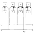
- FIGURE 2 is a block diagram of the installation on a single line of a number n of telephones into which the excluder device of this invention has been incorporated.
- With reference to the drawings, and especially to figure I, it may be understood how the excluder device, which has been given the general reference letter E, is made up by the combination of a rectifier (1) with a relay circuit, which consists of a zener diode (2) and a current divider made up by the resistors (3) and (4). The relay circuit is also associated with a thyristor (5), whose anode is connected to the cathode of the zener diode (2), and to the positive of the rectifier (1), whilst the cathode is connected to earth and the switch to the current divider.
- The device is completed with an independent resistor (6), able to cause a voltage drop equivalent to that which determines the rest of the described system, so that it can, in this way, equilibrate the telephone line.
- As it may be seen from this description and from the drawings, the device consists of four connection leads, of which two belong to the resistor (6), and further two lead to the input of the bridge rectifier (1).
- The device is installed by connecting any one of the resistor leads (I, in the illustrated example ) to one of the poles (LI) of the telephone line, and one of the leads of the bridge rectifier (IV in the example) to the other pole (L2) of the line. Thus, between the other two free leads (II and III) belonging to the resistor and the rectifier respectively, it is possible to have a telephone T, which is controlled as described below.
- As soon as the telephone T is taken off, a determinate current appears in the outlets of the bridge rectifier (1). This current then sets off the relay circuit, which closes the line so that the telephone call can be made. However, once this occurs, the current causing it drops to a level which does not allow activation of the thyristors in the devices installed in the other telephones on the line, leaving them cut off although still in parallel on the line.
- Such an outcome can be understood by observing figure 2, where telephones Tl to Tn are installed on the line oLl-L2. each one incorporating one excluder device, El to En, respectively.
- As it will be understood when the telephone T is taken off, the corresponding relay circuit of the excluder device E will act as an interruptor, cutting off the other telephones. This occurs despite the fact that they are installed in parallel, since the current in their respective excluders does not reach a high enough level to activate their relay circuits.
- It has to be understood that the invention is in no way limited to the details such as described and shown because many variants and modifications may be brought thereto without departing from the scope of this invention.
Claims (1)
- Excluder device for telephones installed in parallel, characterised in that it basically consists of a combination of a full wave bridge rectifier (1) with a relay circuit, made up of a zener diode (2) and a current divider consisting of two resistors (3,4) the relay circuit being associated with a thyristor (5), whose anode is connected to the cathode of the zener diode and to the positive of the rectifier (1), whilst the cathode is connected to earth and the switch to the current divider, and in that an independent resistor is incorporated, able to cause a voltage drop equivalent to that which determines the rest of the telephone system.
Applications Claiming Priority (2)
| Application Number | Priority Date | Filing Date | Title |
|---|---|---|---|
| ES1984282513U ES282513Y (en) | 1984-11-12 | 1984-11-12 | EXCLUSIVE DEVICE FOR PARALLEL-INSTALLED PHONES |
| ES282513U | 1984-11-12 |
Publications (2)
| Publication Number | Publication Date |
|---|---|
| EP0182393A2 true EP0182393A2 (en) | 1986-05-28 |
| EP0182393A3 EP0182393A3 (en) | 1987-09-30 |
Family
ID=8432815
Family Applications (1)
| Application Number | Title | Priority Date | Filing Date |
|---|---|---|---|
| EP85201128A Withdrawn EP0182393A3 (en) | 1984-11-12 | 1985-07-09 | Excluder device for telephones installed in parallel |
Country Status (8)
| Country | Link |
|---|---|
| EP (1) | EP0182393A3 (en) |
| AU (1) | AU572959B2 (en) |
| BR (1) | BR8501351A (en) |
| CA (1) | CA1230438A (en) |
| ES (1) | ES282513Y (en) |
| GR (1) | GR850967B (en) |
| MX (1) | MX156924A (en) |
| PT (1) | PT80026B (en) |
Cited By (3)
| Publication number | Priority date | Publication date | Assignee | Title |
|---|---|---|---|---|
| GB2228649A (en) * | 1989-02-14 | 1990-08-29 | Compact Products Limited | Telephone apparatus |
| EP0348956A3 (en) * | 1988-06-29 | 1990-12-05 | Cselt Centro Studi E Laboratori Telecomunicazioni S.P.A. | A device for the exclusive use of a single telephone line by a telephone set in installations comprising a plurality of telephone sets |
| US6411694B1 (en) | 1999-04-15 | 2002-06-25 | Telefonaktiebolaget Lm Ericsson | Arrangement for improving a telephone system |
Families Citing this family (2)
| Publication number | Priority date | Publication date | Assignee | Title |
|---|---|---|---|---|
| JPS63217758A (en) * | 1987-03-05 | 1988-09-09 | Nec Corp | Branching telephone set |
| AT392974B (en) * | 1989-07-13 | 1991-07-25 | Chemiefaser Lenzing Ag | MIXED POLYIMIDES AND METHOD FOR THE PRODUCTION THEREOF |
Family Cites Families (1)
| Publication number | Priority date | Publication date | Assignee | Title |
|---|---|---|---|---|
| NL7809628A (en) * | 1978-09-21 | 1980-03-25 | Nederlanden Staat | SWITCH FOR MULTIPLE CONNECTED PHONES. |
-
1984
- 1984-11-12 ES ES1984282513U patent/ES282513Y/en not_active Expired
-
1985
- 1985-02-14 AU AU38727/85A patent/AU572959B2/en not_active Ceased
- 1985-02-18 MX MX204354A patent/MX156924A/en unknown
- 1985-02-28 PT PT80026A patent/PT80026B/en not_active IP Right Cessation
- 1985-03-12 CA CA000476309A patent/CA1230438A/en not_active Expired
- 1985-03-26 BR BR8501351A patent/BR8501351A/en unknown
- 1985-04-22 GR GR850967A patent/GR850967B/el unknown
- 1985-07-09 EP EP85201128A patent/EP0182393A3/en not_active Withdrawn
Cited By (3)
| Publication number | Priority date | Publication date | Assignee | Title |
|---|---|---|---|---|
| EP0348956A3 (en) * | 1988-06-29 | 1990-12-05 | Cselt Centro Studi E Laboratori Telecomunicazioni S.P.A. | A device for the exclusive use of a single telephone line by a telephone set in installations comprising a plurality of telephone sets |
| GB2228649A (en) * | 1989-02-14 | 1990-08-29 | Compact Products Limited | Telephone apparatus |
| US6411694B1 (en) | 1999-04-15 | 2002-06-25 | Telefonaktiebolaget Lm Ericsson | Arrangement for improving a telephone system |
Also Published As
| Publication number | Publication date |
|---|---|
| GR850967B (en) | 1985-11-25 |
| MX156924A (en) | 1988-10-14 |
| EP0182393A3 (en) | 1987-09-30 |
| AU3872785A (en) | 1986-05-22 |
| CA1230438A (en) | 1987-12-15 |
| ES282513U (en) | 1986-03-16 |
| BR8501351A (en) | 1986-10-14 |
| PT80026A (en) | 1985-03-01 |
| PT80026B (en) | 1986-10-28 |
| ES282513Y (en) | 1986-10-01 |
| AU572959B2 (en) | 1988-05-19 |
Similar Documents
| Publication | Publication Date | Title |
|---|---|---|
| US4710949A (en) | Telephone line fault locating device | |
| EP0817349A3 (en) | High voltage protection circuits | |
| DK163549B (en) | Voltage controlled transient protection | |
| USRE28283E (en) | Threshold circuit for tone-ringer or like load means | |
| GB963319A (en) | Electronic switching telephone system | |
| US3278687A (en) | Four-layer diode network for identifying parties on a telephone line | |
| EP0182393A2 (en) | Excluder device for telephones installed in parallel | |
| US4382222A (en) | Series regulated rectifier circuit for a battery charging system | |
| US4747128A (en) | Telephone privacy protector | |
| EP0009293A1 (en) | Circuit for connecting, at one time, only one of a number of telephone sets to a subscriber's line | |
| US4039759A (en) | Line security device | |
| US3934089A (en) | Automatic disconnect circuit for subscriber carrier telephone system | |
| US3699265A (en) | Line lockout circuit | |
| EP0224645B1 (en) | Electronic trigger switch for maintenance termination unit | |
| US4947426A (en) | Telephone protection circuit | |
| EP0179812B1 (en) | Circuit for maintaining the dc voltage on an electrically isolated telecommunication line at a reference level | |
| US4324953A (en) | Four-party automatic number identification circuit arrangements | |
| US3389228A (en) | Controlled latching semiconductor switch and switching network | |
| US6965672B1 (en) | Electronic switching system | |
| US4369337A (en) | Central office interface circuit | |
| US5418834A (en) | Maintenance termination units | |
| US3763319A (en) | Impedance responsive voltage booster circuit for telephone systems | |
| US3535461A (en) | Busy detector circuit for step-by-step telephone exchange | |
| US1889466A (en) | Telephone plant | |
| US3956590A (en) | Switching arrangement for switching between different current values by means of mechanical or electronic switches |
Legal Events
| Date | Code | Title | Description |
|---|---|---|---|
| PUAI | Public reference made under article 153(3) epc to a published international application that has entered the european phase |
Free format text: ORIGINAL CODE: 0009012 |
|
| AK | Designated contracting states |
Kind code of ref document: A2 Designated state(s): AT BE CH DE FR GB IT LI LU NL SE |
|
| PUAL | Search report despatched |
Free format text: ORIGINAL CODE: 0009013 |
|
| AK | Designated contracting states |
Kind code of ref document: A3 Designated state(s): AT BE CH DE FR GB IT LI LU NL SE |
|
| 17P | Request for examination filed |
Effective date: 19880316 |
|
| 17Q | First examination report despatched |
Effective date: 19891219 |
|
| STAA | Information on the status of an ep patent application or granted ep patent |
Free format text: STATUS: THE APPLICATION IS DEEMED TO BE WITHDRAWN |
|
| 18D | Application deemed to be withdrawn |
Effective date: 19900501 |
|
| RIN1 | Information on inventor provided before grant (corrected) |
Inventor name: LOPEZ GARCIA, ANTONIO |