EP0182408A1 - Betätigungsvorrichtung und Druckeinstelleinheit für diesen - Google Patents
Betätigungsvorrichtung und Druckeinstelleinheit für diesen Download PDFInfo
- Publication number
- EP0182408A1 EP0182408A1 EP85201704A EP85201704A EP0182408A1 EP 0182408 A1 EP0182408 A1 EP 0182408A1 EP 85201704 A EP85201704 A EP 85201704A EP 85201704 A EP85201704 A EP 85201704A EP 0182408 A1 EP0182408 A1 EP 0182408A1
- Authority
- EP
- European Patent Office
- Prior art keywords
- medium
- chamber
- unit
- pressure
- switch
- Prior art date
- Legal status (The legal status is an assumption and is not a legal conclusion. Google has not performed a legal analysis and makes no representation as to the accuracy of the status listed.)
- Granted
Links
- 230000008878 coupling Effects 0.000 claims description 2
- 238000010168 coupling process Methods 0.000 claims description 2
- 238000005859 coupling reaction Methods 0.000 claims description 2
- 239000012528 membrane Substances 0.000 description 5
- 238000007599 discharging Methods 0.000 description 2
- 230000000903 blocking effect Effects 0.000 description 1
- 230000000295 complement effect Effects 0.000 description 1
- 230000007797 corrosion Effects 0.000 description 1
- 238000005260 corrosion Methods 0.000 description 1
- 238000006073 displacement reaction Methods 0.000 description 1
- 206010016256 fatigue Diseases 0.000 description 1
- 238000009434 installation Methods 0.000 description 1
- 239000007788 liquid Substances 0.000 description 1
- 239000000463 material Substances 0.000 description 1
- 238000007789 sealing Methods 0.000 description 1
- 208000024891 symptom Diseases 0.000 description 1
Images

Classifications
-
- F—MECHANICAL ENGINEERING; LIGHTING; HEATING; WEAPONS; BLASTING
- F16—ENGINEERING ELEMENTS AND UNITS; GENERAL MEASURES FOR PRODUCING AND MAINTAINING EFFECTIVE FUNCTIONING OF MACHINES OR INSTALLATIONS; THERMAL INSULATION IN GENERAL
- F16K—VALVES; TAPS; COCKS; ACTUATING-FLOATS; DEVICES FOR VENTING OR AERATING
- F16K31/00—Actuating devices; Operating means; Releasing devices
- F16K31/12—Actuating devices; Operating means; Releasing devices actuated by fluid
- F16K31/16—Actuating devices; Operating means; Releasing devices actuated by fluid with a mechanism, other than pulling-or pushing-rod, between fluid motor and closure member
- F16K31/163—Actuating devices; Operating means; Releasing devices actuated by fluid with a mechanism, other than pulling-or pushing-rod, between fluid motor and closure member the fluid acting on a piston
- F16K31/1635—Actuating devices; Operating means; Releasing devices actuated by fluid with a mechanism, other than pulling-or pushing-rod, between fluid motor and closure member the fluid acting on a piston for rotating valves
-
- F—MECHANICAL ENGINEERING; LIGHTING; HEATING; WEAPONS; BLASTING
- F15—FLUID-PRESSURE ACTUATORS; HYDRAULICS OR PNEUMATICS IN GENERAL
- F15B—SYSTEMS ACTING BY MEANS OF FLUIDS IN GENERAL; FLUID-PRESSURE ACTUATORS, e.g. SERVOMOTORS; DETAILS OF FLUID-PRESSURE SYSTEMS, NOT OTHERWISE PROVIDED FOR
- F15B20/00—Safety arrangements for fluid actuator systems; Applications of safety devices in fluid actuator systems; Emergency measures for fluid actuator systems
Definitions
- the invention relates to a switch unit engergized by a medium under pressure, comprising a switch provided with a piston chamber having therein at least one reciprocally movable piston which separates a second chamber from a first chamber, and with a drive gear which couples said piston with a switch element.
- Such a switch unit is known and also comprises spring means arranged in the second chamber for returing the piston to its original position should the pressure generated by the medium discontinue, so that the switch is movable between two positions. Because of the use of these spring means, this known switch unit has the drawback that, as a result of material fatigue symptoms, said spring means partially lose their force after a period of time, so that the switch no longer fulfils its function optimally and reliable. The spring means and the interior surface of the second chamber are moreover exposed to corrosion as a result of the suction of outside air into said second chamber. This drawback can however be obviated by arranging new spring means in the switch unit, which however be obviated by considerable fitting costs and the switch unit being temporarily out of use.
- the invention has for its object to provide a switch unit improved in this respect and which does not have the above-mentioned drawbacks because the spring means are omitted.
- the spring means are replaced by means for generating a pressure in the second chamber, that is reduced relative to the pressure prevailing in the first chamber.
- the switch unit also features a pressure adjust unit coupled with the switch, which unit is provided with a medium inlet which on the one hand communicates via a high pressure medium duct with the medium conduit and which on the other hand communicates via a pressure reduction unit and a low pressure medium duct with the second chamber.
- the underpressure limiting valve switches between a first position, whereby the medium inlet is blocked and the high pressure medium bore communicates with an outlet discharging into the outside air, and a second position, whereby said medium inlet communicates with said high pressure medium bore and said outlet discharging into the atmosphere is blocked, the advantage is achieved that, with the fall of the primary pressure to below a minimal value, the supply of medium with the primary pressure is blocked, and the pressue present in the first chamber is simultaneously released into the atmosphere, so that the switch unit moves to a position which is also a safety position.
- the secondary pressure is limited to a maximum value, so that it is possible in all circumstances to switch the switch unit between both positions.
- the switch unit can be operated in a simple manner because, with said switch element in the first position, medium with primary pressure is carried into the chamber, and with said element in the second position, the prevailing pressure in the first chamber is released into the atmosphere.
- a failsafe switch unit is obtained if the switch unit is energizable from outside, and if during energizing said switch element is in the first position.
- a particularly preferred switch unit is obtained if the pressure adjust unit is given the form of an integral block and the medium inlet is coupled via gastight connecting means on the one hand with a section of the low pressure medium bore and on the other hand with a section of the low pressure medium bore arranged in the switch.
- the pressure switch unit can be manufactured beforehand as a whole and possibly also be applied to existing switches, if the outlets of said pressure switch unit correspond within determined tolerance limits with the inlets of such a switch for the low pressure and high pressure medium bores.
- a pressure increase is generated therein which is substantially equal to 1 bar by compressing the medium in said second chamber by displacement of the cylinder.
- Said pressure adjust unit is characterized by an integral block which comprises a medium inlet, the pressure reduction unit and a high and low pressure medium bore, and which is provided with gastight connecting means for coupling said bores with the medium conduit and low pressure medium bore section arranged in the switch unit, respectively.
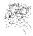
- Fig. 1 shows a switch unit 2 energized by a medium under pressure 1, for example a gas, for operating a shut-off valve 4 arranged in a conduit piece 3.
- Said switch unit 2 comprises a switch 5 and a pressure adjust unit 6 according to the invention arranged thereon.
- the switch 5 is provided with a piston chamber 7 having therein two coupled reciprocally movable pistons 8, 9 which separate second chambers 11 situated on either side of said pistons 8, 9 form a first chamber 10 situated between both said pistons 8, 9.
- a medium conduit 12 emerges into said first chamber 10.
- Each piston 8, 9 is provided with three guide elements 13, 14 and 15, whereby guide element 15 is provided with a rack 16 which grips onto a pinion 18 arranged on a rotary shaft 17.
- Said rack 16 and pinion 18 form here the drive mechanism which couples both pistons 8, 9 with a switch element illustrated by said rotary shaft 17 which can be operated manually on the one hand via shaft stump 19 and is provided on the other hand in a manner not shown with a form complementary to a shut-off valve end 20.
- the piston chamber 7 is formed by a cylindrical piece and two covers 23 arranged thereon with the aid of attaching means 22.
- the pressure adjust unit 6 is provided with a medium inlet 24 which communicates on the one hand via a high pressure medium bore 25 with medium conduit 12 and which on the other hand communicates via a pressure reduction unit 26 and a low pressure medium bore 27 with both the two chambers 11.
- the pressure reduction unit 26 according to fig. 1 consists of a ball-bearing 28 which is under spring pretensioning of a spring 29 and which is pressed against a seat 30.
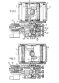
- FIGS 2-5 inclusive show another pressure adjust unit 40 coupled with the switch 5, which unit is also provided with medium inlet 24 which communicates on the one hand via high pressure medium bore 25 with medium conduit 12 that emerges into the first chamber 10, and which communicates on the other hand via pressure reduction unit 41 and low pressure medium duct 27 with both the two chambers 11.
- An underpressure limiting valve 42 is accomodated in the high pressure medium bore 25. Said valve 42 continues to block said high pressure medium bore 25 until the pressure input supplied via medium inlet 24 exceeds a pre-selected minimum value that is adjusted with the spring. Said valve 42 then first opens and medium flows to pressure reduction unit 41. Said pressure reduction unit 41 has the purpose of forming and keeping constant the secondary pressure (the operative pressure in the second chambers) derived from the primary pressure, irrespective of changed primary pressure and of the medium used. The primary pressure must always be higher than the secondary (operative) pressure.
- the pressure reduction unit 41 adjusts the secondary pressure with the aid of a membrane 43.
- One side 44 of said membrane 43 is exposed to the primary pressure, while a spring 46, the spring force whereof is adjustable using an adjusting screw 47, acts upon the other side 45.
- a spring 46 the spring force whereof is adjustable using an adjusting screw 47
- said membrane 43 moves against said spring 46, and with the aid of a valve body 48 attached to said membrane 43 alters the operative section of a valve seat 49.
- said valve body 48 comes to lie on said valve seat 49 and closes off the passage. At that moment the maximum secondary pressure in low pressure medium duct 27 is reached. If the pressure in the second chambers 11 falls, membrane 43 then moves to the position indicated by dashed lines, and medium with the high primary pressure can pass valve body 48 until the maximum adjustable secondary pressure is again reached.
- An underpressure limiting valve 50 is also arrranged in low pressure medium bore 27. Should the primary pressure fall or be removed suddenly, said underpressure limiting valve 50 prevents the medium pressure prevailing in the second chambers 11 from likewise falling or being lost (see also fig. 4).
- the pressure adjust unit 40 is in addition provided with an electrically energizable switch element 52 accomodated in the high pressure medium duct 25, which element switches between a first position, whereby medium inlet 24 communicates with the first chamber 10 (fig. 3), and a second postion whereby the communication between said medium inlet 24 and said first chamber 10 is blocked and said first chamber 10 communicates with the atmosphere (fig. 2).
- Said switch element 52 is provided with magnet 53 which acts upon an anchor 55 operating under the spring force of spring 54. When said magnet 53 is energized, said anchor 55 is moved counter to the spring force of spring 54, and medium inlet 24 communicates vai high pressure medium bore 25 and medium conduit 12 with the first chamber 10.
- An outlet 56 communicating with the atmosphere is simultaneously blocked with the aid of anchor 55 (fig.
- Underpressure limiting valve 42 is therefore also equipped with a valve disc 57, which, if the primary pressure falls below a minimum value, is pressed against a valve seat 58 with the aid of spring 59.
- High pressure medium bore 25 communicates simultaneously via a passage 60 around the disc shank 61 with an outlet 62 which emerges into the atmosphere (fig. 4). In this way is achieved that, when primary pressure falls below the minimum while switch element 52 is energized, the first chamber expels air and both pistons 8 and 9 move towards one another and thereby assume the failsafe position.
- the overpressure limiting valve 51 has the function that, if as a result of play 63 between for example a sealing ring 64 and piston 8, medium at high pressure flows out of the first chamber 10 to the second chamber 11, said higher pressure is released via outlet 65 into the atmosphere, until a miximum secondary pressure is again attained. Because in these circumstances underpressure limiting valve 50 blocks low pressure medium bore 27, there is sufficient pressure present in both second chambers 11 to enable pistons 8 and 9 to be moved towards one another so as to again reach the failsafe position, either when switch element 52 is not energized and/or when underpressure limiting valve 42 is in a position blocking medium inlet 24.
- gastight connecting means 66 have to be present between said switch 5 and both said pressure adjust units.
- this pressure difference is as small as possible. This can be achieved by choosing a stroke volume for both pistons 8 and 9 at least greater than the volume of both the chambers 11 and the stroke volume of both said pistons 8, 9 is adjusted to a value substantially equal to 2.5 bar, the pressure difference is equal to a maximum 1 bar.
- the pressure adjust unit can be used on different types of switch, whereby, depending on the stroke volumes of the pistons 8, 9 and the volumes of both the second chambers 11, and adjustable pressure can always be set in both said second chambers 11 using the pressure reduction unit, so that an optimal pressure difference resulting from the movement of both said pistons 8, 9 can be found, and an optimal moment can be applied on rotary shaft 17 for operating the shut-off valve to be coupled with said rotary shaft 17.
- pressure adjust unit 6 is constructed such that, with the loss of pressure on the medium inlet or with a fall below a preadjusted value, the pressure in the first chamber 10 increases and in this way the pistons are moved to a position which can correspond substantially with a failsafe position of the switch to be operated by the switch unit 2.
- the pressure adjust unit can also be used with a swich provided with only a single piston and consequently with a single second chamber.
- Air is preferably used as medium, but other gaseous media and possibly liquid media are in principle also usable.
Landscapes
- Engineering & Computer Science (AREA)
- General Engineering & Computer Science (AREA)
- Mechanical Engineering (AREA)
- Chemical & Material Sciences (AREA)
- Analytical Chemistry (AREA)
- Physics & Mathematics (AREA)
- Fluid Mechanics (AREA)
- Vehicle Body Suspensions (AREA)
- Fluid-Damping Devices (AREA)
- Fluid-Driven Valves (AREA)
- Switches Operated By Changes In Physical Conditions (AREA)
- Control Of Fluid Pressure (AREA)
- Fluid-Pressure Circuits (AREA)
Priority Applications (1)
| Application Number | Priority Date | Filing Date | Title |
|---|---|---|---|
| AT85201704T ATE42385T1 (de) | 1984-10-24 | 1985-10-17 | Betaetigungsvorrichtung und druckeinstelleinheit fuer diesen. |
Applications Claiming Priority (2)
| Application Number | Priority Date | Filing Date | Title |
|---|---|---|---|
| NL8403234A NL8403234A (nl) | 1984-10-24 | 1984-10-24 | Schakeleenheid en een drukinsteleenheid daarvoor. |
| NL8403234 | 1984-10-24 |
Publications (2)
| Publication Number | Publication Date |
|---|---|
| EP0182408A1 true EP0182408A1 (de) | 1986-05-28 |
| EP0182408B1 EP0182408B1 (de) | 1989-04-19 |
Family
ID=19844655
Family Applications (1)
| Application Number | Title | Priority Date | Filing Date |
|---|---|---|---|
| EP85201704A Expired EP0182408B1 (de) | 1984-10-24 | 1985-10-17 | Betätigungsvorrichtung und Druckeinstelleinheit für diesen |
Country Status (4)
| Country | Link |
|---|---|
| EP (1) | EP0182408B1 (de) |
| AT (1) | ATE42385T1 (de) |
| DE (1) | DE3569603D1 (de) |
| NL (1) | NL8403234A (de) |
Cited By (4)
| Publication number | Priority date | Publication date | Assignee | Title |
|---|---|---|---|---|
| GB2210955A (en) * | 1987-10-08 | 1989-06-21 | Rucker Co | Rotary valve with shear seals |
| EP0797035A1 (de) * | 1996-03-22 | 1997-09-24 | Worcester Controls Corporation | Pneumatischer Stellantrieb mit endmontierter Steuervorrichtung |
| FR2781861A1 (fr) * | 1998-07-31 | 2000-02-04 | Buracco Sa | Dispositif de commande d'une vanne quart de tour |
| WO2003027552A1 (en) * | 2001-09-27 | 2003-04-03 | Honeywell International Inc. | Dual actuator air turbine starter valve |
Citations (7)
| Publication number | Priority date | Publication date | Assignee | Title |
|---|---|---|---|---|
| US2539709A (en) * | 1948-08-12 | 1951-01-30 | Toronto Star Ltd | Air circuit and valve for air saving |
| DE1157872B (de) * | 1960-05-20 | 1963-11-21 | Sarl Cie Auxiliaire Ind | Pneumatischer Antrieb fuer Ventile od. dgl. |
| CH480544A (de) * | 1968-10-01 | 1969-10-31 | Waldenmaier J E H | Kraftkolbenantrieb für Armaturen, insbesondere ein Regelungsorgan |
| DE2020568A1 (de) * | 1969-04-28 | 1970-11-05 | Argenton S A | Ventilsteuerung |
| FR2127281A5 (de) * | 1971-03-03 | 1972-10-13 | Ellingsen Karl | |
| FR2354464A1 (fr) * | 1976-06-08 | 1978-01-06 | Shoketsu Kinzoku Kogyo Kk | Circuit fluidique comprenant un mecanisme de commande |
| GB2095759A (en) * | 1981-03-26 | 1982-10-06 | Rexnord Inc | Energy-conserving apparatus for a piston cylinder arrangement |
-
1984
- 1984-10-24 NL NL8403234A patent/NL8403234A/nl not_active Application Discontinuation
-
1985
- 1985-10-17 DE DE8585201704T patent/DE3569603D1/de not_active Expired
- 1985-10-17 EP EP85201704A patent/EP0182408B1/de not_active Expired
- 1985-10-17 AT AT85201704T patent/ATE42385T1/de not_active IP Right Cessation
Patent Citations (7)
| Publication number | Priority date | Publication date | Assignee | Title |
|---|---|---|---|---|
| US2539709A (en) * | 1948-08-12 | 1951-01-30 | Toronto Star Ltd | Air circuit and valve for air saving |
| DE1157872B (de) * | 1960-05-20 | 1963-11-21 | Sarl Cie Auxiliaire Ind | Pneumatischer Antrieb fuer Ventile od. dgl. |
| CH480544A (de) * | 1968-10-01 | 1969-10-31 | Waldenmaier J E H | Kraftkolbenantrieb für Armaturen, insbesondere ein Regelungsorgan |
| DE2020568A1 (de) * | 1969-04-28 | 1970-11-05 | Argenton S A | Ventilsteuerung |
| FR2127281A5 (de) * | 1971-03-03 | 1972-10-13 | Ellingsen Karl | |
| FR2354464A1 (fr) * | 1976-06-08 | 1978-01-06 | Shoketsu Kinzoku Kogyo Kk | Circuit fluidique comprenant un mecanisme de commande |
| GB2095759A (en) * | 1981-03-26 | 1982-10-06 | Rexnord Inc | Energy-conserving apparatus for a piston cylinder arrangement |
Cited By (7)
| Publication number | Priority date | Publication date | Assignee | Title |
|---|---|---|---|---|
| GB2210955A (en) * | 1987-10-08 | 1989-06-21 | Rucker Co | Rotary valve with shear seals |
| GB2210955B (en) * | 1987-10-08 | 1991-09-18 | Rucker Co | Rotary shear seal hydraulic valve |
| EP0797035A1 (de) * | 1996-03-22 | 1997-09-24 | Worcester Controls Corporation | Pneumatischer Stellantrieb mit endmontierter Steuervorrichtung |
| US5865419A (en) * | 1996-03-22 | 1999-02-02 | Worcestor Controls Licenseco, Inc. | Pneumatic actuator having an end mounted control device |
| FR2781861A1 (fr) * | 1998-07-31 | 2000-02-04 | Buracco Sa | Dispositif de commande d'une vanne quart de tour |
| WO2003027552A1 (en) * | 2001-09-27 | 2003-04-03 | Honeywell International Inc. | Dual actuator air turbine starter valve |
| US6684898B2 (en) | 2001-09-27 | 2004-02-03 | Honeywell International Inc. | Dual actuator air turbine starter valve |
Also Published As
| Publication number | Publication date |
|---|---|
| ATE42385T1 (de) | 1989-05-15 |
| NL8403234A (nl) | 1986-05-16 |
| EP0182408B1 (de) | 1989-04-19 |
| DE3569603D1 (en) | 1989-05-24 |
Similar Documents
| Publication | Publication Date | Title |
|---|---|---|
| AU657661B2 (en) | Boom control valve | |
| US5388968A (en) | Compressor inlet valve | |
| CA2128953A1 (en) | Pilot stage for pressure control valves | |
| US5081904A (en) | Locking valve and flow control valve assembly | |
| US4966196A (en) | Balanced servo-operated multiway valve | |
| GB2275987A (en) | Valve with actuator | |
| WO1997005416B1 (en) | Apparatus and method for reducing water use | |
| EP0427865A4 (en) | Hydraulic driving device of construction equipment | |
| EP0439621A4 (en) | Pressure oil feed circuit device for hydraulic cylinder of operation machine | |
| US4461320A (en) | Manually operable hydraulic control device with hydraulic position retention | |
| WO2002018800A3 (en) | Pilot solenoid control valve with an emergency operator | |
| TW365575B (en) | Mechanical pressure apparatus having a hydraulic-pressure-overload-ratio-valve system | |
| GB1562675A (en) | Nonreturn valve for use with hydraulic apparatus | |
| US4748896A (en) | Safety valve assembly | |
| EP0182408B1 (de) | Betätigungsvorrichtung und Druckeinstelleinheit für diesen | |
| WO1996008398A1 (en) | Solenoid-operated pressure control valve | |
| US4449759A (en) | Service brake accelerator for rail vehicle air brake systems | |
| EP1524163A2 (de) | Modulator | |
| EP0122247A1 (de) | Steuerventil | |
| CA2048415A1 (en) | Gas pressure control valve cartridge | |
| JPH09504854A (ja) | サーボ式ガス調節弁 | |
| SE518374C2 (sv) | Tryckluftförsörjningsanläggning för fordon med en anordning för avkänning av påskjutningsfaser samt förfarande för desamma | |
| EP0097223A1 (de) | Einrichtung zur Dämpfung der Abluft von Ventileinrichtungen | |
| US4724859A (en) | Self-lapping type valve device | |
| EP0869225A3 (de) | Wassermengenbegrenzer |
Legal Events
| Date | Code | Title | Description |
|---|---|---|---|
| PUAI | Public reference made under article 153(3) epc to a published international application that has entered the european phase |
Free format text: ORIGINAL CODE: 0009012 |
|
| AK | Designated contracting states |
Kind code of ref document: A1 Designated state(s): AT BE CH DE FR GB IT LI LU NL SE |
|
| 17P | Request for examination filed |
Effective date: 19861121 |
|
| 17Q | First examination report despatched |
Effective date: 19870915 |
|
| ITF | It: translation for a ep patent filed | ||
| GRAA | (expected) grant |
Free format text: ORIGINAL CODE: 0009210 |
|
| AK | Designated contracting states |
Kind code of ref document: B1 Designated state(s): AT BE CH DE FR GB IT LI LU NL SE |
|
| REF | Corresponds to: |
Ref document number: 42385 Country of ref document: AT Date of ref document: 19890515 Kind code of ref document: T |
|
| REF | Corresponds to: |
Ref document number: 3569603 Country of ref document: DE Date of ref document: 19890524 |
|
| ET | Fr: translation filed | ||
| PG25 | Lapsed in a contracting state [announced via postgrant information from national office to epo] |
Ref country code: LU Free format text: LAPSE BECAUSE OF NON-PAYMENT OF DUE FEES Effective date: 19891031 |
|
| PLBE | No opposition filed within time limit |
Free format text: ORIGINAL CODE: 0009261 |
|
| STAA | Information on the status of an ep patent application or granted ep patent |
Free format text: STATUS: NO OPPOSITION FILED WITHIN TIME LIMIT |
|
| 26N | No opposition filed | ||
| PGFP | Annual fee paid to national office [announced via postgrant information from national office to epo] |
Ref country code: GB Payment date: 19901029 Year of fee payment: 6 Ref country code: BE Payment date: 19901029 Year of fee payment: 6 |
|
| PGFP | Annual fee paid to national office [announced via postgrant information from national office to epo] |
Ref country code: FR Payment date: 19901030 Year of fee payment: 6 |
|
| ITTA | It: last paid annual fee | ||
| PGFP | Annual fee paid to national office [announced via postgrant information from national office to epo] |
Ref country code: SE Payment date: 19901031 Year of fee payment: 6 Ref country code: NL Payment date: 19901031 Year of fee payment: 6 Ref country code: CH Payment date: 19901031 Year of fee payment: 6 |
|
| PGFP | Annual fee paid to national office [announced via postgrant information from national office to epo] |
Ref country code: AT Payment date: 19901114 Year of fee payment: 6 |
|
| PGFP | Annual fee paid to national office [announced via postgrant information from national office to epo] |
Ref country code: LU Payment date: 19901119 Year of fee payment: 6 |
|
| PGFP | Annual fee paid to national office [announced via postgrant information from national office to epo] |
Ref country code: DE Payment date: 19910228 Year of fee payment: 6 |
|
| EPTA | Lu: last paid annual fee | ||
| PG25 | Lapsed in a contracting state [announced via postgrant information from national office to epo] |
Ref country code: GB Effective date: 19911017 Ref country code: AT Effective date: 19911017 |
|
| PG25 | Lapsed in a contracting state [announced via postgrant information from national office to epo] |
Ref country code: SE Effective date: 19911018 |
|
| PG25 | Lapsed in a contracting state [announced via postgrant information from national office to epo] |
Ref country code: LI Effective date: 19911031 Ref country code: CH Effective date: 19911031 Ref country code: BE Effective date: 19911031 |
|
| BERE | Be: lapsed |
Owner name: EL-O-MATIC B.V. Effective date: 19911031 |
|
| PG25 | Lapsed in a contracting state [announced via postgrant information from national office to epo] |
Ref country code: NL Effective date: 19920501 |
|
| NLV4 | Nl: lapsed or anulled due to non-payment of the annual fee | ||
| GBPC | Gb: european patent ceased through non-payment of renewal fee | ||
| PG25 | Lapsed in a contracting state [announced via postgrant information from national office to epo] |
Ref country code: FR Effective date: 19920630 |
|
| REG | Reference to a national code |
Ref country code: CH Ref legal event code: PL |
|
| PG25 | Lapsed in a contracting state [announced via postgrant information from national office to epo] |
Ref country code: DE Effective date: 19920701 |
|
| REG | Reference to a national code |
Ref country code: FR Ref legal event code: ST |
|
| EUG | Se: european patent has lapsed |
Ref document number: 85201704.5 Effective date: 19920510 |