EP0182429A2 - Procédé et agencement destinés à produire des tomographies d'un objet - Google Patents
Procédé et agencement destinés à produire des tomographies d'un objet Download PDFInfo
- Publication number
- EP0182429A2 EP0182429A2 EP85201835A EP85201835A EP0182429A2 EP 0182429 A2 EP0182429 A2 EP 0182429A2 EP 85201835 A EP85201835 A EP 85201835A EP 85201835 A EP85201835 A EP 85201835A EP 0182429 A2 EP0182429 A2 EP 0182429A2
- Authority
- EP
- European Patent Office
- Prior art keywords
- memory
- image
- layer
- pixel
- values
- Prior art date
- Legal status (The legal status is an assumption and is not a legal conclusion. Google has not performed a legal analysis and makes no representation as to the accuracy of the status listed.)
- Granted
Links
Images


Classifications
-
- G—PHYSICS
- G06—COMPUTING OR CALCULATING; COUNTING
- G06T—IMAGE DATA PROCESSING OR GENERATION, IN GENERAL
- G06T12/00—Tomographic reconstruction from projections
- G06T12/20—Inverse problem, i.e. transformations from projection space into object space
-
- G—PHYSICS
- G06—COMPUTING OR CALCULATING; COUNTING
- G06T—IMAGE DATA PROCESSING OR GENERATION, IN GENERAL
- G06T2211/00—Image generation
- G06T2211/40—Computed tomography
- G06T2211/424—Iterative
-
- Y—GENERAL TAGGING OF NEW TECHNOLOGICAL DEVELOPMENTS; GENERAL TAGGING OF CROSS-SECTIONAL TECHNOLOGIES SPANNING OVER SEVERAL SECTIONS OF THE IPC; TECHNICAL SUBJECTS COVERED BY FORMER USPC CROSS-REFERENCE ART COLLECTIONS [XRACs] AND DIGESTS
- Y10—TECHNICAL SUBJECTS COVERED BY FORMER USPC
- Y10S—TECHNICAL SUBJECTS COVERED BY FORMER USPC CROSS-REFERENCE ART COLLECTIONS [XRACs] AND DIGESTS
- Y10S378/00—X-ray or gamma ray systems or devices
- Y10S378/901—Computer tomography program or processor
Definitions
- the invention relates to a method for generating slice images of an object which is irradiated from a plurality of radiation source positions in order to produce separate individual images, image values dependent on the absorption in its pixels being stored in a first memory for each individual image and a slice image value corresponding to the absorption for each layer pixel the image points geometrically assigned to the layer pixel are derived from the stored image values and an arrangement for carrying out the method.
- Such a method is known from US Pat. No. 3,499,146 and from DE-OS 32 37 572.
- the layer image value for a pixel of the layer is formed by superimposing the image values of those pixels that are geometrically assigned to the layer pixel.
- the slice image value of a slice pixel is formed by that image value of the pixels of the individual images geometrically assigned to it that corresponds to the lowest absorption.
- the object of the present invention is to provide a method which delivers more precise slice images with little storage effort.
- the invention is based on the knowledge that, after carrying out steps b) to e), a value is stored in the third memory for each pixel which should be proportional to the image value of this point in the first memory if the images of the individual layers are not affected by errors would be.
- the difference derived in step f) from the values stored for each pixel is therefore a measure of the error in the generation of the slice images from the values stored in the second memory for the different pixels. These Difference is therefore used to modify the value stored in the second memory for this pixel according to step g).
- values are stored in the second memory for each pixel of each individual image, which as a rule no longer correspond to the original image values, but with the help of which more accurate images of each layer can be created than with the aid of the one in the first Memory stored image values of the pixels.
- the reconstruction of the object in layers, which cover the entire object volume, is practically a three-dimensional reconstruction, with the aid of which the values stored in the second memory for the pixels of the various individual images are modified.
- the storage space requirement is relatively small. Only three memories are required, which have a memory location for each pixel of each individual image.
- steps b) to g) are carried out at least once more between steps g) and h).
- steps b) and g) again the third memory must be deleted.
- the values stored in the second memory are modified more and more in the sense of an iterative control process in such a way that the slice images generated with the aid of these values represent the actual absorption distribution in the slice more and more precisely.
- each layer pixel in each individual image is geometrically assigned to only one pixel.
- the layers are selected such that each layer pixel in each individual image is geometrically assigned to only one pixel.
- the layers Select any, but then usually several pixels of a single image must be used for the reconstruction of a slice pixel, the values assigned to these pixels being received with a weight that depends on the position of the pixels in relation to the slice pixel to be reconstructed. This significantly increases the effort.
- only one image point is required from each individual image in order to determine the image value of the layer image point.
- An arrangement for carrying out the method according to claim 1 is provided with a radiation source arrangement for generating a plurality of individual images of the object from a respective radiation source position, with an image converter for converting each individual image into an electrical signal or into a sequence of image values, and with a first memory arrangement for storing these Provide image values and it is provided that a second memory arrangement for storing modified image values for each pixel of each individual image is provided, that a third memory arrangement operated as an accumulator is provided for storing layer image values for each pixel of each individual image, that a first computing device is provided , which for each pixel forms the difference between the value stored for it in the third memory, multiplied by a normalization factor and the image value stored in the first memory and this difference to the content of this B Image point allocated in the second memory forms a layer image processing unit is provided which forms a layer image value for a plurality of layers for each layer image point from the modified image values of the geometrically assigned image points stored in the second memory, and that a second computing device is provided which records the
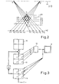
- an object 1 of four radiation sources 2, 3, 4 and 5 is e.g. X-ray tubes, whose emission centers or focal spots lie on the corner points of a square.
- the four radiation sources emit bundles of rays, each of which is illustrated in the drawing by a straight line, but which, however, cover the entire object and which practically coincide in a plane parallel to the plane of the square, which preferably also intersects object 1.
- the radiation sources emit the radiation with the same intensity and the same radiation duration.
- the x-ray radiation influenced by the object 1 is converted by an image sensor 6, for example an x-ray image intensifier, the optical axis of which extends perpendicular to the plane of the square, into four spatially separate individual images such that each individual image produces the x-ray silhouette generated by one of the radiation sources 2 to 5 of object 1 represents.
- the four Single images are converted by an image pickup tube 7 into an electrical signal, which is converted with the aid of an analog-digital converter 8 into a sequence of binary-coded data words, which is fed via a demultiplexer 9 to a unit 10 for generating layer images, which is generated by means of a Image display unit 11 are reproduced.
- Each of the data words generated by the analog-to-digital converter represents the image value, which is dependent on the absorption, in a small area of a single image, which is referred to in the following simply as a pixel.
- Each individual image consists of a large number of such pixels - e.g. 512 lines and 512 columns - so that the analog-digital converter also delivers 512 x 512 data words for each frame.
- A1 denotes the plane in which the radiation sources 2... 5 are located and A2 the input plane of the image sensor 6.
- the plane A1 there are two radiation sources Q and Q ', each of which is a beam for irradiating the object 1 send out.
- the plane A2 five points P1 ... P5, which are located at equal distances from one another, are represented, which represent a line of pixels of a single image generated by the source Q, it being assumed for simplicity that a single image consists of 5 ⁇ 5 pixels.
- Five pixels P1 '... P5' of a line of the single image generated by the radiation source Q ' are also shown.
- the radiation source Q is connected by five beams to the five pixels P1 ...
- the two radiation groups intersect in a variety of (Layer image) points that lie in only nine (layer) planes E1 ... E9. This also applies if one takes into account that the individual images are actually two-dimensional and that instead of two radiation sources, four are present on the corner points of a square. With n pixels in a line, 2n-1 such layer planes would result.
- the values assigned to the individual layer pixels of such a layer can be derived from the image values of the individual pixels, for example by summation or averaging, as described in US Pat. No. 3,499,146.
- the slice image value for the slice pixel L15 in the plane E5 is derived from the image values of the pixels P1 and P1 ', the value for the adjacent slice pixel from the image values of the pixels P2 and P2' and the slice pixel located on the other side in it Level from the image values of the pixels P5 and P5 '.
- the values assigned to the layer pixels are derived from the image values of the corresponding pixels, for example P1, P1 '; P2, P2 'etc. formed.
- the layer image value for the layer pixel L14 is determined from the image values of the pixels P1 and P2 ', for the adjacent point of this layer the image values of the pixels P2 and P3' are used, etc. That is, the values for the layer pixels for this layer are derived from the pixels which result from the individual images offset by one pixel.
- layer E3 the layer pixels result by shifting the individual images by two pixels, etc.
- each layer image can be separated by only one pixel in each Define single image.
- the invention is not restricted to the layers lying as described; however, several pixels must then be used to determine the value of a slice pixel, which significantly increases the reconstruction effort.
- the unit 10 comprises (FIG. 1) has three memory 12, 13 and 14, each of which has as many memory locations, such as pixels are available in the four frames.
- the image values supplied by the analog-digital converter 8 and present as binary-coded data words are stored in the first memory 12. At the beginning, these values are also transferred to the second memory 13, while the content of the third memory 14 is deleted.
- a slice image value is formed, which is intended to characterize the absorption of the object in the slice pixel L15.
- This value can be formed in the slice image decoder by summing the values stored for the said pixels in the second memory 13, by averaging, by selecting the smallest or largest value or in some other way.
- the layer image value determined in this way for a layer pixel (L15) is added in the third memory 14 to the content of the memory locations which belong to the geometrically assigned pixels (P1, P1 ', ). This is repeated for all points of the layer (E5).
- the image of the first layer (E5) is then stored in the memory 14.
- the slice image determined by the decoder 15 can also be fed to a playback unit 11 at the same time, so that the slice image (which is initially still subject to errors) can be viewed by the user during the processing operation.
- Another layer is then processed, for example layer E4.
- the value formed by the layer image decoder 14 for a point in this layer, for example point L14, is in turn added to the content of the memory locations which belong to pixels which are geometrically assigned to this layer pixel (for example P1, P2 ').
- this layer has also been processed in the manner described, further layers follow until all layers E1 ... E9 have been processed.
- the memory location assigned to a pixel of a single image contains the sum of the values calculated by the layer image decoder for the layer pixels geometrically assigned to this pixel; For example, the storage space for P1 contains the sum of the slice image values calculated for points L 11 ... L15.
- the sum stored in the third memory 14 for the individual pixels of the individual images would, apart from a normalization factor that is the same for all image values, that in the first memory 12 for these Pixels correspond to stored image values. This prerequisite is generally not met with the slice image decoders known to date. If, for example, the value for a layer pixel is formed from the sum or from the mean value of the values belonging to the pixels geometrically assigned to the respective layer pixel, the image of one layer contains the structures of all other layers, albeit more or less out of focus.
- the deviations between the image values or sums stored in the first memory 12 and the third memory 14 for one pixel due to the lack of this requirement are used in the invention to modify the image values in the second memory 13 in such a way that one due to the modified ones Values produced layer image better reflects the actual absorption distribution in the layer.
- the difference between the image value stored in the first memory 12 and the total value stored in the third memory 14 for the same pixel, multiplied by a normalization factor N, is formed for each pixel.
- This difference is added in the second memory 13 to the content of the memory location which is assigned to the same pixel of the same single image.
- the third memory 14 is deleted and the cycle described can start again. Due to the modification of the signals stored in the second memory however, there are better slice images. This improvement is more pronounced the more often the cycle described is run through.
- the image values supplied in this way to the first memory 12a ... 12d are also added via the arithmetic units 16a ... 16d and 17a ... 17d to the content of the memory locations provided in the second memory 13a ... 13d with the same address . Since the second memory 13a ... 13d and the third memory 14a ... 14d were previously deleted, this means that the content of the partial memory 12a is transferred to the partial memory 13a, the content of the partial memory 12b is transferred to the partial memory 13b, and so on each partial memory initially contains the image values of a single image.
- the addressing of the memory locations required for this can be carried out accordingly, as in connection with DE-OS 32 37 572, esp. Fig. 4, described.
- the slice image decoder 15 forms, for example by summation, a slice image value which is supplied to the partial memories 14a ... 14d via the arithmetic units 18a ... 18d and stored there under the same addresses under which the values from the memories 13a ... 13d were called. This is repeated for all layer pixels of a layer, after which the layer pixels of a second layer are processed.
- the slice image values generated in the process are then added to the content of the memory locations by means of the arithmetic units 18a ... 18d, the addresses of which correspond to the addresses of the values previously called up in the partial memories 13a ... 13d.
- the values assigned to the individual pixels are called up in succession in each of the partial image memories 14a ... 14d, weighted with a normalization factor in one of the circuits 19a ... 19d and in one of the arithmetic units 16a ... 16d the partial memory 12a ... 12d subtracts the stored image value for the same pixel.
- the difference formed in this way is added in units 17a ... 17d to the content of that memory location which has the same address or is assigned to the same pixel.
- the partial memories 14a ... 14d are deleted.
- the cycle already described then begins (generation of slice images, addition of the slice image values belonging to the same pixels in the partial memories 14a ... 14d, normalization of the sum values, comparison with the image values, addition of the difference to the content of the (modified) values in the partial memories 13a ... 13d, etc.) again.
- the layer images then generated with the aid of the again modified values in the partial memories 13a ... 13d reflect the absorption distribution in the respective layer even better.
- the cycle described can be repeated several times.
- the layer images generated can be reproduced with the reproduction unit 11 already during the individual cycles, which presupposes that the latter is provided with a memory for the layer pixels.
- the user can then cancel the processing cycle at a certain stage. However, it is also possible to specify a certain number of processing cycles from the outset.
- the circuits 19a ... 19d by means of which the content of the partial memories 14a ... 14d is weighted with the normalization factor N, could also be arranged between the slice image decoder 15 and the arrhythmic units 18a ... 18d or between them and the partial memories .
- the individual values fed to the partial memories 14a ... 14d would then be smaller, which would increase rounding errors.
Landscapes
- Physics & Mathematics (AREA)
- General Physics & Mathematics (AREA)
- Engineering & Computer Science (AREA)
- Theoretical Computer Science (AREA)
- Apparatus For Radiation Diagnosis (AREA)
- Image Processing (AREA)
- Conversion Of X-Rays Into Visible Images (AREA)
- Image Analysis (AREA)
Applications Claiming Priority (2)
| Application Number | Priority Date | Filing Date | Title |
|---|---|---|---|
| DE3442448 | 1984-11-22 | ||
| DE19843442448 DE3442448A1 (de) | 1984-11-22 | 1984-11-22 | Verfahren und anordnung zum erzeugen von schichtbildern eines objektes |
Publications (3)
| Publication Number | Publication Date |
|---|---|
| EP0182429A2 true EP0182429A2 (fr) | 1986-05-28 |
| EP0182429A3 EP0182429A3 (en) | 1989-05-24 |
| EP0182429B1 EP0182429B1 (fr) | 1992-02-26 |
Family
ID=6250793
Family Applications (1)
| Application Number | Title | Priority Date | Filing Date |
|---|---|---|---|
| EP85201835A Expired - Lifetime EP0182429B1 (fr) | 1984-11-22 | 1985-11-11 | Procédé et agencement destinés à produire des tomographies d'un objet |
Country Status (4)
| Country | Link |
|---|---|
| US (1) | US5022066A (fr) |
| EP (1) | EP0182429B1 (fr) |
| JP (1) | JPS61130900A (fr) |
| DE (2) | DE3442448A1 (fr) |
Cited By (2)
| Publication number | Priority date | Publication date | Assignee | Title |
|---|---|---|---|---|
| GB2208194A (en) * | 1987-05-02 | 1989-03-08 | Rolls Royce Plc | Tomographic imaging |
| EP0284158A3 (en) * | 1987-03-26 | 1989-09-27 | Philips Patentverwaltung Gmbh | In the area of examination, processing for radiating from many radiation sources positions |
Families Citing this family (8)
| Publication number | Priority date | Publication date | Assignee | Title |
|---|---|---|---|---|
| US5384861A (en) * | 1991-06-24 | 1995-01-24 | Picker International, Inc. | Multi-parameter image display with real time interpolation |
| US5651047A (en) * | 1993-01-25 | 1997-07-22 | Cardiac Mariners, Incorporated | Maneuverable and locateable catheters |
| DE4304332A1 (de) * | 1993-02-13 | 1994-08-18 | Philips Patentverwaltung | Verfahren zur Erzeugung von Schichtbildern und Anordnung zur Durchführung des Verfahrens |
| US5682412A (en) * | 1993-04-05 | 1997-10-28 | Cardiac Mariners, Incorporated | X-ray source |
| US6181764B1 (en) | 1998-10-06 | 2001-01-30 | Cardiac Mariners, Inc. | Image reconstruction for wide depth of field images |
| US6178223B1 (en) | 1998-10-06 | 2001-01-23 | Cardiac Mariners, Inc. | Image reconstruction method and apparatus |
| JP4599073B2 (ja) * | 2004-03-22 | 2010-12-15 | 株式会社東芝 | X線断層撮影装置 |
| WO2006116316A2 (fr) | 2005-04-22 | 2006-11-02 | University Of Chicago | Systeme d'imagerie |
Family Cites Families (4)
| Publication number | Priority date | Publication date | Assignee | Title |
|---|---|---|---|---|
| US3499146A (en) * | 1966-10-10 | 1970-03-03 | Albert G Richards | Variable depth laminagraphy with means for highlighting the detail of selected lamina |
| DE2517268C2 (de) * | 1975-04-18 | 1982-10-14 | Philips Patentverwaltung Gmbh, 2000 Hamburg | Verfahren zur Erzeugung von verwischungsschattenfreien Röntgen-Schichtbildern und Anordnung zur Durchführung des Verfahrens |
| DE3237572A1 (de) * | 1982-10-09 | 1984-04-12 | Philips Patentverwaltung Gmbh, 2000 Hamburg | Verfahren zum erzeugen von schichtbildern |
| US4598369A (en) * | 1983-05-02 | 1986-07-01 | Picker International, Inc. | Tomography apparatus and method |
-
1984
- 1984-11-22 DE DE19843442448 patent/DE3442448A1/de not_active Withdrawn
-
1985
- 1985-11-11 EP EP85201835A patent/EP0182429B1/fr not_active Expired - Lifetime
- 1985-11-11 DE DE8585201835T patent/DE3585428D1/de not_active Expired - Lifetime
- 1985-11-15 US US06/798,507 patent/US5022066A/en not_active Expired - Fee Related
- 1985-11-20 JP JP60258810A patent/JPS61130900A/ja active Granted
Cited By (2)
| Publication number | Priority date | Publication date | Assignee | Title |
|---|---|---|---|---|
| EP0284158A3 (en) * | 1987-03-26 | 1989-09-27 | Philips Patentverwaltung Gmbh | In the area of examination, processing for radiating from many radiation sources positions |
| GB2208194A (en) * | 1987-05-02 | 1989-03-08 | Rolls Royce Plc | Tomographic imaging |
Also Published As
| Publication number | Publication date |
|---|---|
| JPS61130900A (ja) | 1986-06-18 |
| EP0182429A3 (en) | 1989-05-24 |
| JPH0576301B2 (fr) | 1993-10-22 |
| DE3442448A1 (de) | 1986-05-22 |
| DE3585428D1 (de) | 1992-04-02 |
| EP0182429B1 (fr) | 1992-02-26 |
| US5022066A (en) | 1991-06-04 |
Similar Documents
| Publication | Publication Date | Title |
|---|---|---|
| EP0004258B1 (fr) | Appareil de tomographie de rayonnement à travers un corps | |
| DE3886323T2 (de) | Interpolationsverfahren. | |
| DE3348093C2 (fr) | ||
| DE3710502C2 (fr) | ||
| DE69127986T2 (de) | Anordnung zum geometrischen Korrigieren eines verzerrten Bildes | |
| DE2848376C2 (de) | Einrichtung zur Nachkorrektur von Standardfarbkorrekturen bei der Farbbildaufzeichnung | |
| CH643373A5 (de) | Verfahren und vorrichtung zur herstellung gerasterter druckformen. | |
| DE2705640A1 (de) | Rechnersystem fuer den bildaufbau eines koerperschnittbildes und verfahren zum betrieb des rechnersystems | |
| DE2754687A1 (de) | Korrelationsanordnung | |
| DE3732435C2 (fr) | ||
| EP0182429B1 (fr) | Procédé et agencement destinés à produire des tomographies d'un objet | |
| DE2931420A1 (de) | Verfahren und vorrichtung zur farbbildreproduktion | |
| DE3024459A1 (de) | Pyramideninterpolation | |
| DE3431483A1 (de) | Verfahren und vorrichtung zur verarbeitung von bilddaten bei der bildreproduktion | |
| DE4234985C2 (de) | Verfahren zum Transformieren von Farbsignalen und Vorrichtung zur Durchführung des Verfahrens | |
| DE3503400A1 (de) | Verfahren und vorrichtung zur erzeugung von halbtonpunkten | |
| EP0625762B1 (fr) | Méthode de correction des images radiographiques et dispositif de réalisation de la méthode | |
| EP0106402B1 (fr) | Procédé pour produire des représentations tomographiques | |
| EP0284158B1 (fr) | Dans le domaine de l'examen, procédé de rayonnement à partir de plusieurs positions de sources de rayonnement | |
| DE2556012A1 (de) | Verfahren und anordnung zur ermittlung der raeumlichen verteilung einer strahlung in einer ebene eines koerpers | |
| DE2645416A1 (de) | Verfahren und anordnung zur ermittlung der verteilung der absorption eines koerpers | |
| DE2012728B2 (de) | Verfahren zur elektrooptischen Aufzeichnung von gerasterten Halbtonbildern | |
| DE69031317T2 (de) | Bearbeitung von einem zweidimensionalen Teilchen eines digitalen Bildsignals | |
| DE2919776C2 (de) | Computer-Tomograph | |
| DE2919775C2 (de) | Computer-Tomograph |
Legal Events
| Date | Code | Title | Description |
|---|---|---|---|
| PUAI | Public reference made under article 153(3) epc to a published international application that has entered the european phase |
Free format text: ORIGINAL CODE: 0009012 |
|
| AK | Designated contracting states |
Kind code of ref document: A2 Designated state(s): DE FR GB NL |
|
| RAP1 | Party data changed (applicant data changed or rights of an application transferred) |
Owner name: N.V. PHILIPS' GLOEILAMPENFABRIEKEN Owner name: PHILIPS PATENTVERWALTUNG GMBH |
|
| PUAL | Search report despatched |
Free format text: ORIGINAL CODE: 0009013 |
|
| AK | Designated contracting states |
Kind code of ref document: A3 Designated state(s): DE FR GB NL |
|
| 17P | Request for examination filed |
Effective date: 19891117 |
|
| 17Q | First examination report despatched |
Effective date: 19910419 |
|
| GRAA | (expected) grant |
Free format text: ORIGINAL CODE: 0009210 |
|
| AK | Designated contracting states |
Kind code of ref document: B1 Designated state(s): DE FR GB NL |
|
| PG25 | Lapsed in a contracting state [announced via postgrant information from national office to epo] |
Ref country code: NL Effective date: 19920226 |
|
| REF | Corresponds to: |
Ref document number: 3585428 Country of ref document: DE Date of ref document: 19920402 |
|
| GBT | Gb: translation of ep patent filed (gb section 77(6)(a)/1977) | ||
| ET | Fr: translation filed | ||
| NLV1 | Nl: lapsed or annulled due to failure to fulfill the requirements of art. 29p and 29m of the patents act | ||
| PLBE | No opposition filed within time limit |
Free format text: ORIGINAL CODE: 0009261 |
|
| STAA | Information on the status of an ep patent application or granted ep patent |
Free format text: STATUS: NO OPPOSITION FILED WITHIN TIME LIMIT |
|
| 26N | No opposition filed | ||
| REG | Reference to a national code |
Ref country code: FR Ref legal event code: CD |
|
| PGFP | Annual fee paid to national office [announced via postgrant information from national office to epo] |
Ref country code: GB Payment date: 19961101 Year of fee payment: 12 |
|
| PGFP | Annual fee paid to national office [announced via postgrant information from national office to epo] |
Ref country code: FR Payment date: 19961119 Year of fee payment: 12 |
|
| PGFP | Annual fee paid to national office [announced via postgrant information from national office to epo] |
Ref country code: DE Payment date: 19970127 Year of fee payment: 12 |
|
| PG25 | Lapsed in a contracting state [announced via postgrant information from national office to epo] |
Ref country code: GB Free format text: LAPSE BECAUSE OF NON-PAYMENT OF DUE FEES Effective date: 19971111 |
|
| PG25 | Lapsed in a contracting state [announced via postgrant information from national office to epo] |
Ref country code: FR Free format text: THE PATENT HAS BEEN ANNULLED BY A DECISION OF A NATIONAL AUTHORITY Effective date: 19971130 |
|
| GBPC | Gb: european patent ceased through non-payment of renewal fee |
Effective date: 19971111 |
|
| PG25 | Lapsed in a contracting state [announced via postgrant information from national office to epo] |
Ref country code: DE Free format text: LAPSE BECAUSE OF NON-PAYMENT OF DUE FEES Effective date: 19980801 |
|
| REG | Reference to a national code |
Ref country code: FR Ref legal event code: CD |
|
| REG | Reference to a national code |
Ref country code: FR Ref legal event code: ST |