EP0182433B1 - Verfahren und Vorrichtung zur Temperaturregelung eines Fahrzeugs - Google Patents
Verfahren und Vorrichtung zur Temperaturregelung eines Fahrzeugs Download PDFInfo
- Publication number
- EP0182433B1 EP0182433B1 EP85201857A EP85201857A EP0182433B1 EP 0182433 B1 EP0182433 B1 EP 0182433B1 EP 85201857 A EP85201857 A EP 85201857A EP 85201857 A EP85201857 A EP 85201857A EP 0182433 B1 EP0182433 B1 EP 0182433B1
- Authority
- EP
- European Patent Office
- Prior art keywords
- air
- vehicle
- supplied
- heating
- interior
- Prior art date
- Legal status (The legal status is an assumption and is not a legal conclusion. Google has not performed a legal analysis and makes no representation as to the accuracy of the status listed.)
- Expired
Links
Images

Classifications
-
- B—PERFORMING OPERATIONS; TRANSPORTING
- B61—RAILWAYS
- B61D—BODY DETAILS OR KINDS OF RAILWAY VEHICLES
- B61D27/00—Heating, cooling, ventilating, or air-conditioning
- B61D27/0018—Air-conditioning means, i.e. combining at least two of the following ways of treating or supplying air, namely heating, cooling or ventilating
-
- B—PERFORMING OPERATIONS; TRANSPORTING
- B60—VEHICLES IN GENERAL
- B60H—ARRANGEMENTS OF HEATING, COOLING, VENTILATING OR OTHER AIR-TREATING DEVICES SPECIALLY ADAPTED FOR PASSENGER OR GOODS SPACES OF VEHICLES
- B60H1/00—Heating, cooling or ventilating devices
- B60H1/00357—Air-conditioning arrangements specially adapted for particular vehicles
- B60H1/00371—Air-conditioning arrangements specially adapted for particular vehicles for vehicles carrying large numbers of passengers, e.g. buses
-
- B—PERFORMING OPERATIONS; TRANSPORTING
- B60—VEHICLES IN GENERAL
- B60H—ARRANGEMENTS OF HEATING, COOLING, VENTILATING OR OTHER AIR-TREATING DEVICES SPECIALLY ADAPTED FOR PASSENGER OR GOODS SPACES OF VEHICLES
- B60H1/00—Heating, cooling or ventilating devices
- B60H1/00007—Combined heating, ventilating, or cooling devices
- B60H1/00207—Combined heating, ventilating, or cooling devices characterised by the position of the HVAC devices with respect to the passenger compartment
- B60H2001/00221—Devices in the floor or side wall area of the passenger compartment
-
- B—PERFORMING OPERATIONS; TRANSPORTING
- B60—VEHICLES IN GENERAL
- B60H—ARRANGEMENTS OF HEATING, COOLING, VENTILATING OR OTHER AIR-TREATING DEVICES SPECIALLY ADAPTED FOR PASSENGER OR GOODS SPACES OF VEHICLES
- B60H1/00—Heating, cooling or ventilating devices
- B60H1/00007—Combined heating, ventilating, or cooling devices
- B60H1/00207—Combined heating, ventilating, or cooling devices characterised by the position of the HVAC devices with respect to the passenger compartment
- B60H2001/00235—Devices in the roof area of the passenger compartment
Definitions
- the invention relates to a method for adjusting the temperature in a passengers room bounded by a floor, a roof and upright walls in a vehicle, in particular a motor coach, wherein near both longitudinal sides of the vehicle, near the floor, air is supplied from outside via an air heating device to the passengers room of the vehicle, whilst further outside air is supplied near the roof and the outside air led through the air heating device is regulated dependent on the quantity of heat required to be supplied into the passenger room.
- Vehicles such as motor coaches and the like are put in action quite frequently in cold conditions such as e.g. in winter for conveying passengers to winter-sports areas and the like.
- cold conditions such as e.g. in winter for conveying passengers to winter-sports areas and the like.
- the invention now aims at effecting a method by means of which an even and pleasant temperature can be achieved in the coach while maintaining a regular air-change.
- Figs. 1 and 2 The vehicle diagrammatically illustrated in Figs. 1 and 2 is here formed by a motor coach known by itself, comprising a passengers room 1, which is bounded by a floor 2, upright walls 3 and a roof 4. Near the front side of the bus an entrance door 5 has been provided, whilst also located there is the driver's seat 6.
- an air heating unit 7 which is provided with a radiator fed by cooling water of the combustion engine used for driving the bus and with a fan, whilst said air heating device 7 can be adjusted by the driver to his requirements and dependent of the working conditions, e.g. to direct hot air along the front windows to prevent misting of said windows.
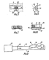
- the air heating device is formed by a radiator to which, as is diagrammatically illustrated in fig. 9, cooling water can be supplied from the abovementioned combustion engine 12 via a supply pipe 13 to which the heating devices 10 and 11 are connected via branch pipes 14, 15 respectively.
- An adjusting valve 16, 17 respectively has been provided to each of the branch pipes for the adjustment of the passage of hot cooling water from the combustion engine 12 to the heating devices 10 and 11, Said cooling water is led back to the engine via a return pipe 18.
- a threeway valve 19 has been provided to the supply pipe 13. In a first position of said valve 19 the cooling water of the engine 12 will be led to the heating devices 10 and 11. In another position of said adjusting valve the supply of cooling water to the heating units 10 and 11 is shut off and the cooling water coming from the engine is passed on to the return pipe 18 direct via a connecting pipe 20.
- air can be supplied to the air supply duct 8 by means of a pair of fans 21 and 22.
- the fan 21 is connected, via a pipe 23, to a suction pipe 24, extending transverse to the longitudinal direction of the vehicle, the ends of said pipe 24 having a direct communication with the outside air.
- the fan 22 sucks air from a closed room 25, located under the passenger room, which e.g. can also be used for storing luggage.
- air can be supplied to the air supply duct 9 via the air heating device 11 by means of a fan 26, which is also connected to the suction pipe 24 and by means of a fan 27, which sucks air from the room 25.
- a temperature sensor 32 has been arranged in the casing 29 for a purpose to be more fully described hereinafter.
- the casing 29 have been insulated relative to the air supply duct 8, 9 respectively by means of insulation material not further illustrated.
- the fans 21, 22 and 26, 27 are provided with non-return valves at their exhaust sides, so that no air can flow back from the air supply ducts 8 and 9 via the fans when the fans are stationary.
- Air supply ducts 33 and 34 extending into the longitudinal direction of the vehicle, have further been provided in the passenger room 1, near the roof at each side of the passenger room. Near the centres of said air supply ducts 33 and 34 a pair of fans 35 and 36 sucking outside air have been arranged which blow the air into the air supply ducts 33 and 34 in opposite directions. Thereby said fans, too, have been provided at their exhaust sides with diagrammatically illustrated non-return valves 37, which oppose the flow of air from the interior of the bus to the outside via said fans.
- exhaust openings 38 which cannot be shut off, have been provided, which have been constructed such that they direct the outflowing air along the roof, as is diagrammatically illustrated in fig 4 by means of the arrow A. Furthermore exhaust nozzles 39 to be operated by the passengers have been provided to the bottom sides of the air supply ducts in the usual manner.
- an air exhaust device has been arranged provided with a casing 40, which has been divided into two parts by means of a vertically standing partition 41.
- grates 42 have been provided in the wall of the casing, via which air can flow from the interior of the passenger room into the casing 40.
- an exhaust grate 43 has been provided at the side of the partition 41 remote from the grates 42.
- a number of passages 44 have been provided, which can be shut off by means of non-return valves 45, which only allow a flow of air in the direction of the grates 42 to the grate 43.
- the room of the casing 44 comprising the exhaust grate 43 has been provided with a connecting stub 46, which has, direct or via a hose connected thereto, a direct communication with the front side of the bus.
- a connecting stub 46 which has, direct or via a hose connected thereto, a direct communication with the front side of the bus.
- the construction of the air supply ducts 8 and 9 and the connection of the fans 21, 22 and 26, 27 respectively to said air supply ducts 8, 9 respectively is thereby such in the embodiment illustrated that via the front par of the air supply duct 9 air sucked from the interior and re-heated via the heating device 11 is supplied to the passenger room, whilst via the rear part of the air supply duct 9, air sucked from outside and led through the heating device 11 is supplied.
- the temperature level desired in the passenger room can be adjusted to a desired value e.g. between 16°C and 26°C.
- the actual temperature in the room is now measured in four places by means of temperature sensors 32 arranged near the exhaust openings 28.
- the number of revolutions of the fan by means of which air sucked from the interior and led along the heating unit 10 is re-supplied to the passenger room via the rear part of the air supply duct 8 will be adjusted by means of the temperature sensor, which has been arranged in the exhaust opening 28 which has been arranged near the rear part of said air supply duct 8. If the temperature decreases to a level below the desired value more air will be displaced by means of said fans, whilst if the temperature increases to a level above the desired value the speed of revolutions of the fans will be reduced in order to displace less air.
- the number of revolutions of the fans 21 and 27 are adjusted by means of which fans outside air led along the heating units 10 and 11 is supplied to the passenger room via the front part of the air supply duct 8 and the rear part of air supply duct 9, respectively. Also here the adjustment is such that if the sensor arranged near the front end of the air supply duct 8 senses too high a temperature the numberof revolutions of the relevantfan 21 will be reduced, whilst if the temperature drops under a desired value the number of revolutions of the fan 21 will be increased again. In a similar manner the number of revolutions of the fan 27 is adjusted.
- the number of revolutions of the air supply fan in the air supply duct 34 is adjusted dependent on the number of revolutions of the fan.21, such that on reducing the number of revolutions of the fan 21 the number of revolutions of the fan in the air supply duct 34 being in action when the heating installation is being used is increased, all this in such a manner that a practically constant quantity of air is always sucked in and supplied to the interior of the passenger room by means of the two fans.
- the number of revolutions of the fan supplying the outside air via the air supply duct 33 when the heating installation is being used is adjusted dependent on the number of revolutions of the fan 26, so that also here said two fans supply a quantity of air to the passenger room of the bus that remains practically even per time unit.
- a temperature sensor has been arranged, by means of which the position of the adjusting valve 16; 17, respectively, can be influenced for adjusting the quantity of water which is supplied to the heating device 10 and to the heating device 11, respectively. In this manner it can be effected that independent of the quantity of air displaced per time unit through the heating device 10, 11 respectively, the temperature of the air heated by means of the heating device 10, 11, respectively, stays practically constantly on a set level of e.g. ⁇ 55°C.
- shut-off valves can be provided near the rear side of the coach near the roof, which are automatically opened when the fans, starting the operate when the heating device is switched off, have reached a certain number of revolutions.
- the two fans which only start operating when the heating units are switched off in the embodiment described above, can be left out as well as the valves which are opened dependent on the speed of revolutions of said fans.
- an air conditioning plant When there is an air conditioning plant present it will be automatically set in operation when the supply of hot water to the heating units is interrupted.
- Normally air supplied via the roof ducts 33, 34 is not pre-heated. When being used in extremely cold conditions, however, means may be provided to pre-heat said air to 2-3°C before supplying it to the interior of the coach.
Landscapes
- Engineering & Computer Science (AREA)
- Mechanical Engineering (AREA)
- Physics & Mathematics (AREA)
- Thermal Sciences (AREA)
- Air-Conditioning For Vehicles (AREA)
- Vehicle Body Suspensions (AREA)
Claims (15)
Priority Applications (1)
| Application Number | Priority Date | Filing Date | Title |
|---|---|---|---|
| AT85201857T ATE30542T1 (de) | 1984-11-17 | 1985-11-12 | Verfahren und vorrichtung zur temperaturregelung eines fahrzeugs. |
Applications Claiming Priority (2)
| Application Number | Priority Date | Filing Date | Title |
|---|---|---|---|
| NL8403512A NL8403512A (nl) | 1984-11-17 | 1984-11-17 | Werkwijze voor het regelen van de temperatuur in een voertuig en voertuig voorzien van een dergelijke temperatuurregeling. |
| NL8403512 | 1984-11-17 |
Publications (2)
| Publication Number | Publication Date |
|---|---|
| EP0182433A1 EP0182433A1 (de) | 1986-05-28 |
| EP0182433B1 true EP0182433B1 (de) | 1987-11-04 |
Family
ID=19844785
Family Applications (1)
| Application Number | Title | Priority Date | Filing Date |
|---|---|---|---|
| EP85201857A Expired EP0182433B1 (de) | 1984-11-17 | 1985-11-12 | Verfahren und Vorrichtung zur Temperaturregelung eines Fahrzeugs |
Country Status (5)
| Country | Link |
|---|---|
| US (1) | US4821956A (de) |
| EP (1) | EP0182433B1 (de) |
| AT (1) | ATE30542T1 (de) |
| DE (1) | DE3560869D1 (de) |
| NL (1) | NL8403512A (de) |
Families Citing this family (8)
| Publication number | Priority date | Publication date | Assignee | Title |
|---|---|---|---|---|
| DE19535373C2 (de) * | 1995-09-25 | 1999-05-27 | Vogel Ind Gmbh | Personenbeförderungsfahrzeug mit Betriebskanal |
| SE510863C2 (sv) * | 1998-02-12 | 1999-06-28 | Uwe Verken Ab | Anordning i ett fluidburet uppvärmningssystem för fordon |
| KR100656627B1 (ko) * | 2005-10-11 | 2006-12-11 | 현대자동차주식회사 | 버스 히터 시스템 |
| DE202006010428U1 (de) * | 2006-07-06 | 2007-09-06 | Hymer-Leichtmetallbau Gmbh & Co. Kg | Klimaanlage in einem Land-, Wasser- oder Luftfahrzeug |
| US20120315836A1 (en) * | 2011-06-07 | 2012-12-13 | Delphi Technologies, Inc. | Assembly for heating, ventilating and conditioning air in an automobile |
| DE102012108411B4 (de) * | 2012-09-10 | 2023-07-06 | Bombardier Transportation Gmbh | Schienenfahrzeug mit einem in einen Gepäckträger teilweise integrierten Lüftungskanal, und Gepäckträgermodul zum Aufbau eines Gepäckträgers |
| CN109532908B (zh) * | 2018-09-07 | 2020-06-19 | 江苏九州电器有限公司 | 具有导流板的车厢电加热器 |
| CN109532907B (zh) * | 2018-09-07 | 2020-06-19 | 江苏九州电器有限公司 | 一种舒适性高的车厢电加热器 |
Family Cites Families (8)
| Publication number | Priority date | Publication date | Assignee | Title |
|---|---|---|---|---|
| US2133067A (en) * | 1936-04-24 | 1938-10-11 | William B Whitsltt | Air conditioning apparatus for railway cars |
| US2476295A (en) * | 1946-11-06 | 1949-07-19 | Edmund E Hans | Air freshening system |
| FR1042902A (fr) * | 1951-04-18 | 1953-11-04 | Daimler Benz Ag | Dispositif de chauffage et d'aération pour véhicules à grande capacité, en particulier pour omnibus automobiles |
| US2794383A (en) * | 1953-05-04 | 1957-06-04 | Budd Co | Air conditioning and ventilating means for vehicles |
| US3520355A (en) * | 1968-10-18 | 1970-07-14 | Budd Co | Air conditioning apparatus for a railway passenger vehicle |
| GB1316429A (en) * | 1969-07-22 | 1973-05-09 | South Wales Transport Co Ltd | Ventilating system for passenger vehicles |
| DE2838425A1 (de) * | 1978-09-02 | 1980-03-13 | Daimler Benz Ag | Heizungs- und belueftungsvorrichtung fuer die obere zone (kopfbereich) eines fahrgastraumes eines fahrzeuges |
| DE3048226C2 (de) * | 1980-12-20 | 1986-11-27 | Brown, Boveri & Cie Ag, 6800 Mannheim | Einrichtung zur Klimatisierung |
-
1984
- 1984-11-17 NL NL8403512A patent/NL8403512A/nl not_active Application Discontinuation
-
1985
- 1985-11-12 DE DE8585201857T patent/DE3560869D1/de not_active Expired
- 1985-11-12 AT AT85201857T patent/ATE30542T1/de not_active IP Right Cessation
- 1985-11-12 EP EP85201857A patent/EP0182433B1/de not_active Expired
-
1987
- 1987-09-29 US US07/102,169 patent/US4821956A/en not_active Expired - Fee Related
Also Published As
| Publication number | Publication date |
|---|---|
| NL8403512A (nl) | 1986-06-16 |
| US4821956A (en) | 1989-04-18 |
| DE3560869D1 (en) | 1987-12-10 |
| ATE30542T1 (de) | 1987-11-15 |
| EP0182433A1 (de) | 1986-05-28 |
Similar Documents
| Publication | Publication Date | Title |
|---|---|---|
| US4852363A (en) | Air conditioner humidity control system | |
| US6581678B1 (en) | Heating or air-conditioning system for a motor vehicle | |
| US5931006A (en) | Vehicle air conditioning unit with an air-conditioning function depending on the external dew point | |
| EP0182433B1 (de) | Verfahren und Vorrichtung zur Temperaturregelung eines Fahrzeugs | |
| US5173078A (en) | Heating and ventilating apparatus for the cabin of a motor vehicle | |
| US6554695B2 (en) | Device for recycling air in a vehicle cabin | |
| CN212950600U (zh) | 一种轨道车辆用空调送风系统 | |
| US6427760B2 (en) | Air-conditioning system for a motor vehicle | |
| GB2235976A (en) | An air conditioning system for vehicles | |
| GB1578643A (en) | Control of the internal enviroment of a coach | |
| US6116329A (en) | Heating or air-conditioning system | |
| KR101403436B1 (ko) | 차량용 공조장치 | |
| CS257945B1 (en) | Device for heating and ventilating electrically driven vehicles' inside space | |
| EP1837216B1 (de) | Kaltluft-Bypass stromabwärts der Mischklappe | |
| JPS606809B2 (ja) | 車輌用空調装置 | |
| US3442449A (en) | Installation for heating and ventilating passenger spaces of motor vehicles | |
| SU1136971A1 (ru) | Отопительно-вентил ционное устройство дл салона транспортного средства | |
| KR101172695B1 (ko) | 차량용 공조장치 | |
| JPS6144891Y2 (de) | ||
| KR0143595B1 (ko) | 대형버스용 공기조화장치 | |
| JPS6227444Y2 (de) | ||
| JPH0126490Y2 (de) | ||
| KR200365529Y1 (ko) | 차량용공기조화케이스 | |
| GB2340221A (en) | Demisting a vehicle | |
| KR20010019970A (ko) | 가습기가 부착된 차량용 냉난방장치 |
Legal Events
| Date | Code | Title | Description |
|---|---|---|---|
| PUAI | Public reference made under article 153(3) epc to a published international application that has entered the european phase |
Free format text: ORIGINAL CODE: 0009012 |
|
| AK | Designated contracting states |
Kind code of ref document: A1 Designated state(s): AT BE CH DE FR GB IT LI LU NL SE |
|
| 17P | Request for examination filed |
Effective date: 19860423 |
|
| 17Q | First examination report despatched |
Effective date: 19861006 |
|
| GRAA | (expected) grant |
Free format text: ORIGINAL CODE: 0009210 |
|
| AK | Designated contracting states |
Kind code of ref document: B1 Designated state(s): AT BE CH DE FR GB IT LI LU NL SE |
|
| REF | Corresponds to: |
Ref document number: 30542 Country of ref document: AT Date of ref document: 19871115 Kind code of ref document: T |
|
| ITF | It: translation for a ep patent filed | ||
| REF | Corresponds to: |
Ref document number: 3560869 Country of ref document: DE Date of ref document: 19871210 |
|
| ET | Fr: translation filed | ||
| PLBE | No opposition filed within time limit |
Free format text: ORIGINAL CODE: 0009261 |
|
| STAA | Information on the status of an ep patent application or granted ep patent |
Free format text: STATUS: NO OPPOSITION FILED WITHIN TIME LIMIT |
|
| 26N | No opposition filed | ||
| ITTA | It: last paid annual fee | ||
| EPTA | Lu: last paid annual fee | ||
| EAL | Se: european patent in force in sweden |
Ref document number: 85201857.1 |
|
| PGFP | Annual fee paid to national office [announced via postgrant information from national office to epo] |
Ref country code: GB Payment date: 19971110 Year of fee payment: 13 |
|
| PGFP | Annual fee paid to national office [announced via postgrant information from national office to epo] |
Ref country code: SE Payment date: 19971113 Year of fee payment: 13 |
|
| PGFP | Annual fee paid to national office [announced via postgrant information from national office to epo] |
Ref country code: LU Payment date: 19971118 Year of fee payment: 13 |
|
| PGFP | Annual fee paid to national office [announced via postgrant information from national office to epo] |
Ref country code: AT Payment date: 19971119 Year of fee payment: 13 |
|
| PGFP | Annual fee paid to national office [announced via postgrant information from national office to epo] |
Ref country code: FR Payment date: 19971125 Year of fee payment: 13 Ref country code: BE Payment date: 19971125 Year of fee payment: 13 |
|
| PGFP | Annual fee paid to national office [announced via postgrant information from national office to epo] |
Ref country code: NL Payment date: 19971130 Year of fee payment: 13 |
|
| PGFP | Annual fee paid to national office [announced via postgrant information from national office to epo] |
Ref country code: CH Payment date: 19971202 Year of fee payment: 13 |
|
| PGFP | Annual fee paid to national office [announced via postgrant information from national office to epo] |
Ref country code: DE Payment date: 19971230 Year of fee payment: 13 |
|
| PG25 | Lapsed in a contracting state [announced via postgrant information from national office to epo] |
Ref country code: LU Free format text: LAPSE BECAUSE OF NON-PAYMENT OF DUE FEES Effective date: 19981112 Ref country code: GB Free format text: LAPSE BECAUSE OF NON-PAYMENT OF DUE FEES Effective date: 19981112 Ref country code: AT Free format text: LAPSE BECAUSE OF NON-PAYMENT OF DUE FEES Effective date: 19981112 |
|
| PG25 | Lapsed in a contracting state [announced via postgrant information from national office to epo] |
Ref country code: SE Free format text: LAPSE BECAUSE OF NON-PAYMENT OF DUE FEES Effective date: 19981113 |
|
| PG25 | Lapsed in a contracting state [announced via postgrant information from national office to epo] |
Ref country code: LI Free format text: LAPSE BECAUSE OF NON-PAYMENT OF DUE FEES Effective date: 19981130 Ref country code: CH Free format text: LAPSE BECAUSE OF NON-PAYMENT OF DUE FEES Effective date: 19981130 Ref country code: BE Free format text: LAPSE BECAUSE OF NON-PAYMENT OF DUE FEES Effective date: 19981130 |
|
| BERE | Be: lapsed |
Owner name: VAN KUIK RUBERTUS JOHANNES PETRUS Effective date: 19981130 |
|
| PG25 | Lapsed in a contracting state [announced via postgrant information from national office to epo] |
Ref country code: NL Free format text: LAPSE BECAUSE OF NON-PAYMENT OF DUE FEES Effective date: 19990601 |
|
| GBPC | Gb: european patent ceased through non-payment of renewal fee |
Effective date: 19981112 |
|
| REG | Reference to a national code |
Ref country code: CH Ref legal event code: PL |
|
| PG25 | Lapsed in a contracting state [announced via postgrant information from national office to epo] |
Ref country code: FR Free format text: LAPSE BECAUSE OF NON-PAYMENT OF DUE FEES Effective date: 19990730 |
|
| EUG | Se: european patent has lapsed |
Ref document number: 85201857.1 |
|
| NLV4 | Nl: lapsed or anulled due to non-payment of the annual fee |
Effective date: 19990601 |
|
| REG | Reference to a national code |
Ref country code: FR Ref legal event code: ST |
|
| PG25 | Lapsed in a contracting state [announced via postgrant information from national office to epo] |
Ref country code: DE Free format text: LAPSE BECAUSE OF NON-PAYMENT OF DUE FEES Effective date: 19990901 |