EP0182439A1 - Fender oder ähnliche Vorrichtung zum Absorbieren von Stosskräften - Google Patents
Fender oder ähnliche Vorrichtung zum Absorbieren von Stosskräften Download PDFInfo
- Publication number
- EP0182439A1 EP0182439A1 EP85201884A EP85201884A EP0182439A1 EP 0182439 A1 EP0182439 A1 EP 0182439A1 EP 85201884 A EP85201884 A EP 85201884A EP 85201884 A EP85201884 A EP 85201884A EP 0182439 A1 EP0182439 A1 EP 0182439A1
- Authority
- EP
- European Patent Office
- Prior art keywords
- fender
- supporting structure
- mooring body
- moored
- vertical axis
- Prior art date
- Legal status (The legal status is an assumption and is not a legal conclusion. Google has not performed a legal analysis and makes no representation as to the accuracy of the status listed.)
- Granted
Links
- XLYOFNOQVPJJNP-UHFFFAOYSA-N water Substances O XLYOFNOQVPJJNP-UHFFFAOYSA-N 0.000 claims description 10
- 230000015572 biosynthetic process Effects 0.000 description 1
- 230000008878 coupling Effects 0.000 description 1
- 238000010168 coupling process Methods 0.000 description 1
- 238000005859 coupling reaction Methods 0.000 description 1
- 238000006073 displacement reaction Methods 0.000 description 1
- 239000000725 suspension Substances 0.000 description 1
Images


Classifications
-
- E—FIXED CONSTRUCTIONS
- E02—HYDRAULIC ENGINEERING; FOUNDATIONS; SOIL SHIFTING
- E02B—HYDRAULIC ENGINEERING
- E02B3/00—Engineering works in connection with control or use of streams, rivers, coasts, or other marine sites; Sealings or joints for engineering works in general
- E02B3/20—Equipment for shipping on coasts, in harbours or on other fixed marine structures, e.g. bollards
- E02B3/26—Fenders
-
- Y—GENERAL TAGGING OF NEW TECHNOLOGICAL DEVELOPMENTS; GENERAL TAGGING OF CROSS-SECTIONAL TECHNOLOGIES SPANNING OVER SEVERAL SECTIONS OF THE IPC; TECHNICAL SUBJECTS COVERED BY FORMER USPC CROSS-REFERENCE ART COLLECTIONS [XRACs] AND DIGESTS
- Y02—TECHNOLOGIES OR APPLICATIONS FOR MITIGATION OR ADAPTATION AGAINST CLIMATE CHANGE
- Y02A—TECHNOLOGIES FOR ADAPTATION TO CLIMATE CHANGE
- Y02A30/00—Adapting or protecting infrastructure or their operation
- Y02A30/30—Adapting or protecting infrastructure or their operation in transportation, e.g. on roads, waterways or railways
Definitions
- the invention relates to a fender or similar device for absorbing forces of impact coming from a mooring or moored floating device, such as a vessel, which fender has been suspended from a mooring body anchored with respect to the water bottom and being of the type allowing the moored device to swing around it about a vertical axis of rotation, said fender comprising a supporting structure, which surrounds said vertical axis of rotation and the mooring body with more than 180° and which is loaded by weights and which at least at the side of the device to be moored or moored respectively is at a distance of the mooring body, which supporting structure at a plurality of locations is suspended from the mooring body by means of movable connecting members attached at points which are at a higher level than the supporting structure.
- a fender of this type is known from e.g. FR-A-2 260 663.
- Said known fender is formed by a rectangular annular weight suspended by means of rods or chains from a tower such that when the fender has to take up impact forces from a vessel the weight is moved horizontally because the rods of chains form a parallel guide system.
- the weight Upon displacement by a vessel the weight is lifted only slightly and remains parallel to its original position by being displaced substantially horizontally. Due to this the forces counteracting the bumping mass of the vessel remain substantially constant.
- the weight has to be very large to be able to generate sufficiently quick a horizontal force component counteracting the force of impact coming from the vessel.
- Purpose of the invention is to provide a fender which in combination with a mooring body operates more effective and/or requires less weight for quickly generating a return force.
- this purpose is achieved in that the supporting structure has been suspended by means of connecting members which all converge upwardly towards each other and are attached at points of the mooring body which lie on or adjacent to the vertical axis of rotation.
- the connecting means in principle are directed to a single spot
- the fender upon engagement by a vessel, is tilted in such a way that the portion of the fender turned away from the vessel is lifted upwardly. This generates the return force very quickly, in particular if said end of the fender turned away from the vessel is lifted out of the water.
- said end of the fender may have additional weight load.
- the fender can extend around the mooring body and can be circular or polygonal.
- the fender also can have the shape of a horse shoe or U-shape and in that case should at any rate be designed such that it can rotate around the mooring body.
- the fender according to the invention can be made in the form of a bumping cushion at the side which will be engaged by the vessel. This, however, is not necessary because its operation is based upon the function of the weight of the fender which weight due to the swinging movement about substantially a single pivot point very quickly generates a sufficiently large return force component. This has a consequence that in certain circumstances the weight can be lower for generating a return force of sufficient magnitude to absorb the impact forces to be expected.
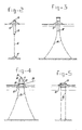
- Figure 1 shows a tower 1, which has been attached to the sea bottom and which extends far above the water level 2. At the upper end the tower 1 supports a derrick 3 with counterweight 4 for handling hoses to be connected to a vessel which hoses are not shown but are connected to a rotatable conduit coupling 5 or swivel placed on top of the tower.
- a tanker 6 has been moored by means of mooring cables 7 to a ring 8 which is rotatably supported for rotation about a vertical axis upon the upper portion of the tower.
- Said ring 8 suspends a heavy ring 12 by means of cables 9,10,11 etc., which ring functions as a fender. If the vessel 6, as shown in Figure 1, bumps against the fender 12 then said fender at the location of the impact will be forced further downwardly as indicated with interrupted lines, and due to the suspension by means of cables which extend upwardly and towards each other, the opposite end, indicated at 13, will be tilted upwardly and out of the water. The mass of the fender 12 then will generate a moment about an imaginative pivot lying at the extension of the cables 9 and 10, which moment generates a return force against the bow of the vessel 6 and forces said vessel backwards with large force.
- the fender is of the same type as shown in Figure 1 and suspended from the top 14 of a cylindrical buoy 15 which by means of a tension resisting member 16 has been attached to a bottom anchor 17.
- a cylindrical buoy 18 is used as well, which, however, has been anchored by means of anchor chains 19.
- the fender has been suspended in a similar way.
- the fender has been shown at the level of the water level.
- the mooring body again has the form of a buoy 20, anchored by means of chains 21 and carrying a turn table 22 for an anchor line 23, which turn table has been provided with a column 24 to which the cables 9 and 10 are connected which support the fender 12 which in this case lies under water.
- Figure 5 diagrammatically shows that the same principle can be used as well with a semi-submersable floating platform structure 25, which by means of vertically downwardly extending cables 26 has been attached to the sea bottom.
- the fender extends around the mooring body and in top view can be circular.
- Heavier weights at the side turned away from the vessel to be moored can be applied with any type of fender according to the invention and has the advantage to generate larger return valve components.
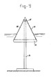
- Figure 9 shows an embodiment comprising a tower 34 rigidly mounted upon the sea bottom and a fender 35 in the form of a ring, which fender has been supported from the top of the column 34 by means of a closed conical sleeve 36, the top of which is supported on the top of the column, e.g. by means of a universal joint 37.
- Said conical sleeve may be the only means of connecting the fender 35 with the top of the column but also may be a sleeve which surrounds chains 38.
- the conical sleeve 36 has the advantage that under arctic circumstances the continuous movements of the conical sleeve through the water prevent the formation of ice around the mooring arrangement. Chains of course do the same, but are less effective.
Landscapes
- Engineering & Computer Science (AREA)
- General Engineering & Computer Science (AREA)
- Ocean & Marine Engineering (AREA)
- Environmental & Geological Engineering (AREA)
- Mechanical Engineering (AREA)
- Civil Engineering (AREA)
- Structural Engineering (AREA)
- Vibration Dampers (AREA)
- Jib Cranes (AREA)
- Revetment (AREA)
- Laying Of Electric Cables Or Lines Outside (AREA)
Applications Claiming Priority (2)
| Application Number | Priority Date | Filing Date | Title |
|---|---|---|---|
| NL8403519 | 1984-11-19 | ||
| NL8403519A NL8403519A (nl) | 1984-11-19 | 1984-11-19 | Fender of dergelijke inrichting voor het opvangen van stoten. |
Publications (2)
| Publication Number | Publication Date |
|---|---|
| EP0182439A1 true EP0182439A1 (de) | 1986-05-28 |
| EP0182439B1 EP0182439B1 (de) | 1990-03-14 |
Family
ID=19844790
Family Applications (1)
| Application Number | Title | Priority Date | Filing Date |
|---|---|---|---|
| EP85201884A Expired - Lifetime EP0182439B1 (de) | 1984-11-19 | 1985-11-15 | Fender oder ähnliche Vorrichtung zum Absorbieren von Stosskräften |
Country Status (7)
| Country | Link |
|---|---|
| US (1) | US4686924A (de) |
| EP (1) | EP0182439B1 (de) |
| JP (1) | JPS61179909A (de) |
| CN (1) | CN1006316B (de) |
| CA (1) | CA1247381A (de) |
| NL (1) | NL8403519A (de) |
| NO (1) | NO167791C (de) |
Cited By (2)
| Publication number | Priority date | Publication date | Assignee | Title |
|---|---|---|---|---|
| EP0253925A1 (de) * | 1986-07-23 | 1988-01-27 | Bluewater Terminal Systems N.V. | Einrichtung zum Festmachen |
| CN104389695A (zh) * | 2014-10-25 | 2015-03-04 | 罗桦 | 船用三元固液推进剂火箭防护设备 |
Families Citing this family (8)
| Publication number | Priority date | Publication date | Assignee | Title |
|---|---|---|---|---|
| KR0140461B1 (ko) * | 1994-07-12 | 1998-06-01 | 김광호 | 전자렌지 |
| US7007623B2 (en) * | 2002-11-12 | 2006-03-07 | Fmc Technologies, Inc. | Retrieval and connection system for a disconnectable mooring yoke |
| US6851892B2 (en) * | 2003-02-10 | 2005-02-08 | Saudi Arabian Oil Company | Marine impact-absorbing structure |
| JP4734055B2 (ja) * | 2005-07-22 | 2011-07-27 | 富士フイルム株式会社 | アセチレン性三重結合を有するモノマーの重合体、これを用いる膜形成用組成物、絶縁膜および電子デバイス |
| WO2010132433A2 (en) * | 2009-05-11 | 2010-11-18 | American Global Maritime, Inc. | Drilling rig ice protector apparatus and methods |
| CN103321140A (zh) * | 2012-03-23 | 2013-09-25 | 范淑君 | 桥梁的水上防撞装置及其系统 |
| CN107610798B (zh) * | 2017-09-30 | 2023-11-03 | 中国船舶重工集团公司第七一九研究所 | 用于海上核能发电的奖杯式浮动核电站 |
| CN114197400B (zh) * | 2021-12-08 | 2023-06-30 | 重庆市排水有限公司 | 贴护式箱涵防撞体系 |
Citations (5)
| Publication number | Priority date | Publication date | Assignee | Title |
|---|---|---|---|---|
| DE1041426B (de) * | 1954-11-27 | 1958-10-16 | Otto Woeltinger | Schwimmender, mehrfach aufgehaengter Ringfender |
| US3901040A (en) * | 1974-10-07 | 1975-08-26 | William A Sandberg | Collision bumper for offshore structures |
| FR2260663A1 (en) * | 1974-02-07 | 1975-09-05 | Gtmbtp | Pendulum type shock absorber for ship's moorings - has inclined suspension cables for mass carrying spring bumpers |
| FR2514451A1 (fr) * | 1981-10-13 | 1983-04-15 | Precontrainte Structures Ste F | Dispositif de defense d'une structure, notamment off shore contre les impacts d'objets de grandes dimensions, notamment de bateaux |
| US4446806A (en) * | 1980-05-05 | 1984-05-08 | Morrison-Knudsen Company, Inc. | Single point mooring and fender |
Family Cites Families (7)
| Publication number | Priority date | Publication date | Assignee | Title |
|---|---|---|---|---|
| GB1383012A (en) * | 1971-01-11 | 1975-02-05 | Larsen O J F | Apparatus for preventing and reducing scours in a bed supporting a body of water |
| US3778854A (en) * | 1971-03-16 | 1973-12-18 | Santa Fe Int Corp | Mooring and oil transfer apparatus |
| US4038830A (en) * | 1975-01-08 | 1977-08-02 | Sumner Maurice N | Modular geometric offshore structures system |
| US4098212A (en) * | 1977-02-17 | 1978-07-04 | Shell Oil Company | Tanker loading terminal |
| SU1015041A1 (ru) * | 1981-03-18 | 1983-04-30 | Государственный Проектный Институт "Днепрпроектстальконструкция" | Морска бурова платформа |
| US4497593A (en) * | 1982-10-13 | 1985-02-05 | The B. F. Goodrich Company | Floating structures |
| NL184312C (nl) * | 1983-06-07 | 1989-06-16 | Single Buoy Moorings | Afmeerinrichting met op verticale kabels geleide fenders. |
-
1984
- 1984-11-19 NL NL8403519A patent/NL8403519A/nl not_active Application Discontinuation
-
1985
- 1985-11-05 US US06/795,236 patent/US4686924A/en not_active Expired - Lifetime
- 1985-11-08 CA CA000494867A patent/CA1247381A/en not_active Expired
- 1985-11-15 EP EP85201884A patent/EP0182439B1/de not_active Expired - Lifetime
- 1985-11-18 CN CN85108491A patent/CN1006316B/zh not_active Expired
- 1985-11-18 NO NO854592A patent/NO167791C/no unknown
- 1985-11-18 JP JP60256843A patent/JPS61179909A/ja active Granted
Patent Citations (5)
| Publication number | Priority date | Publication date | Assignee | Title |
|---|---|---|---|---|
| DE1041426B (de) * | 1954-11-27 | 1958-10-16 | Otto Woeltinger | Schwimmender, mehrfach aufgehaengter Ringfender |
| FR2260663A1 (en) * | 1974-02-07 | 1975-09-05 | Gtmbtp | Pendulum type shock absorber for ship's moorings - has inclined suspension cables for mass carrying spring bumpers |
| US3901040A (en) * | 1974-10-07 | 1975-08-26 | William A Sandberg | Collision bumper for offshore structures |
| US4446806A (en) * | 1980-05-05 | 1984-05-08 | Morrison-Knudsen Company, Inc. | Single point mooring and fender |
| FR2514451A1 (fr) * | 1981-10-13 | 1983-04-15 | Precontrainte Structures Ste F | Dispositif de defense d'une structure, notamment off shore contre les impacts d'objets de grandes dimensions, notamment de bateaux |
Cited By (3)
| Publication number | Priority date | Publication date | Assignee | Title |
|---|---|---|---|---|
| EP0253925A1 (de) * | 1986-07-23 | 1988-01-27 | Bluewater Terminal Systems N.V. | Einrichtung zum Festmachen |
| CN104389695A (zh) * | 2014-10-25 | 2015-03-04 | 罗桦 | 船用三元固液推进剂火箭防护设备 |
| CN104389695B (zh) * | 2014-10-25 | 2016-06-22 | 贺州学院 | 船用三元固液推进剂火箭防护设备 |
Also Published As
| Publication number | Publication date |
|---|---|
| CN1006316B (zh) | 1990-01-03 |
| JPS61179909A (ja) | 1986-08-12 |
| NO167791B (no) | 1991-09-02 |
| US4686924A (en) | 1987-08-18 |
| EP0182439B1 (de) | 1990-03-14 |
| CA1247381A (en) | 1988-12-28 |
| NO167791C (no) | 1991-12-11 |
| NL8403519A (nl) | 1986-06-16 |
| CN85108491A (zh) | 1986-10-01 |
| JPH0519606B2 (de) | 1993-03-17 |
| NO854592L (no) | 1986-05-20 |
Similar Documents
| Publication | Publication Date | Title |
|---|---|---|
| US4655641A (en) | Apparatus for aligning a platform deck and jacket | |
| EP0096446B2 (de) | System zum Halten eines Schwimmkörpers in einer festen Position relativ zu einem anderen Körper | |
| US6171028B1 (en) | Device and method for lifting a sea-going structure, for instance a drilling platform | |
| US5041038A (en) | Offshore loading system | |
| US4031582A (en) | Floating structure | |
| US4176615A (en) | Mooring attachment for single point mooring terminals | |
| US4686924A (en) | Fender or similar device for absorbing forces of impact | |
| EP0096445A1 (de) | System zum Halten eines Schwimmkörpers in einer festen Position relativ zu einem anderen Körper | |
| US5816183A (en) | Submerged CALM buoy | |
| US4226204A (en) | Off-shore mooring device for a large-sized floating body | |
| US4567843A (en) | Mooring system | |
| US4784079A (en) | Apparatus such as a working platform which by means of tension loaded tension member has been anchored and which has been provided with means for mooring a vessel | |
| US6131224A (en) | Coupling device for transfer between a static structure and a dynamic structure | |
| EP0079404B1 (de) | Einpunkt-Verankerungsboje mit starrem Arm | |
| US4441448A (en) | Controlled mooring | |
| US7484470B2 (en) | Soft quay mooring system | |
| EP0407662B2 (de) | Gerät zum Positionieren einer Boje | |
| US6869325B1 (en) | Rotating tower system for transferring hydrocarbons to a ship | |
| EP0252544B1 (de) | Vorrichtung zum Festmachen | |
| EP0134596A1 (de) | Verankerungsboje | |
| EP0096119A1 (de) | Einpunktbefestigungs-System mit starrem Arm für schwimmende Fahrzeuge | |
| US5716249A (en) | Mooring means | |
| JPS59134091A (ja) | 単一点係船装置 | |
| EP0253925A1 (de) | Einrichtung zum Festmachen | |
| GB1584374A (en) | Riser and yoke mooring system |
Legal Events
| Date | Code | Title | Description |
|---|---|---|---|
| PUAI | Public reference made under article 153(3) epc to a published international application that has entered the european phase |
Free format text: ORIGINAL CODE: 0009012 |
|
| AK | Designated contracting states |
Kind code of ref document: A1 Designated state(s): CH FR GB IT LI NL |
|
| 17P | Request for examination filed |
Effective date: 19860617 |
|
| 17Q | First examination report despatched |
Effective date: 19871208 |
|
| GRAA | (expected) grant |
Free format text: ORIGINAL CODE: 0009210 |
|
| AK | Designated contracting states |
Kind code of ref document: B1 Designated state(s): CH FR GB IT LI NL |
|
| ITF | It: translation for a ep patent filed | ||
| ET | Fr: translation filed | ||
| ITTA | It: last paid annual fee | ||
| PLBE | No opposition filed within time limit |
Free format text: ORIGINAL CODE: 0009261 |
|
| STAA | Information on the status of an ep patent application or granted ep patent |
Free format text: STATUS: NO OPPOSITION FILED WITHIN TIME LIMIT |
|
| 26N | No opposition filed | ||
| PGFP | Annual fee paid to national office [announced via postgrant information from national office to epo] |
Ref country code: CH Payment date: 19981120 Year of fee payment: 14 |
|
| PG25 | Lapsed in a contracting state [announced via postgrant information from national office to epo] |
Ref country code: LI Free format text: LAPSE BECAUSE OF NON-PAYMENT OF DUE FEES Effective date: 19991130 Ref country code: CH Free format text: LAPSE BECAUSE OF NON-PAYMENT OF DUE FEES Effective date: 19991130 |
|
| REG | Reference to a national code |
Ref country code: CH Ref legal event code: PL |
|
| REG | Reference to a national code |
Ref country code: GB Ref legal event code: IF02 |
|
| PGFP | Annual fee paid to national office [announced via postgrant information from national office to epo] |
Ref country code: FR Payment date: 20031110 Year of fee payment: 19 |
|
| PGFP | Annual fee paid to national office [announced via postgrant information from national office to epo] |
Ref country code: GB Payment date: 20031112 Year of fee payment: 19 |
|
| PGFP | Annual fee paid to national office [announced via postgrant information from national office to epo] |
Ref country code: NL Payment date: 20041029 Year of fee payment: 20 |
|
| PG25 | Lapsed in a contracting state [announced via postgrant information from national office to epo] |
Ref country code: GB Free format text: LAPSE BECAUSE OF NON-PAYMENT OF DUE FEES Effective date: 20041115 |
|
| GBPC | Gb: european patent ceased through non-payment of renewal fee |
Effective date: 20041115 |
|
| PG25 | Lapsed in a contracting state [announced via postgrant information from national office to epo] |
Ref country code: FR Free format text: LAPSE BECAUSE OF NON-PAYMENT OF DUE FEES Effective date: 20050729 |
|
| REG | Reference to a national code |
Ref country code: FR Ref legal event code: ST |
|
| PG25 | Lapsed in a contracting state [announced via postgrant information from national office to epo] |
Ref country code: NL Free format text: LAPSE BECAUSE OF EXPIRATION OF PROTECTION Effective date: 20051115 |
|
| NLV7 | Nl: ceased due to reaching the maximum lifetime of a patent |
Effective date: 20051115 |