EP0182444A2 - Revêtement de sol marqueté en vinyle ainsi que son obtention - Google Patents
Revêtement de sol marqueté en vinyle ainsi que son obtention Download PDFInfo
- Publication number
- EP0182444A2 EP0182444A2 EP85201963A EP85201963A EP0182444A2 EP 0182444 A2 EP0182444 A2 EP 0182444A2 EP 85201963 A EP85201963 A EP 85201963A EP 85201963 A EP85201963 A EP 85201963A EP 0182444 A2 EP0182444 A2 EP 0182444A2
- Authority
- EP
- European Patent Office
- Prior art keywords
- plastisol
- layer
- colored
- plugs
- pattern
- Prior art date
- Legal status (The legal status is an assumption and is not a legal conclusion. Google has not performed a legal analysis and makes no representation as to the accuracy of the status listed.)
- Withdrawn
Links
- 238000000034 method Methods 0.000 title claims abstract description 10
- 125000000391 vinyl group Chemical group [H]C([*])=C([H])[H] 0.000 title abstract description 44
- 229920002554 vinyl polymer Polymers 0.000 title abstract description 44
- 238000004519 manufacturing process Methods 0.000 title abstract description 9
- 238000009408 flooring Methods 0.000 title description 7
- 229920001944 Plastisol Polymers 0.000 claims abstract description 93
- 239000004999 plastisol Substances 0.000 claims abstract description 93
- 239000000463 material Substances 0.000 claims description 23
- 239000011152 fibreglass Substances 0.000 claims description 7
- 238000000151 deposition Methods 0.000 claims description 5
- 238000007639 printing Methods 0.000 abstract description 46
- 238000004049 embossing Methods 0.000 abstract description 11
- 238000001035 drying Methods 0.000 abstract description 4
- 239000011248 coating agent Substances 0.000 abstract description 3
- 238000000576 coating method Methods 0.000 abstract description 3
- 239000012467 final product Substances 0.000 abstract description 3
- 238000010022 rotary screen printing Methods 0.000 abstract description 3
- 239000011449 brick Substances 0.000 description 25
- 239000004570 mortar (masonry) Substances 0.000 description 21
- 239000003086 colorant Substances 0.000 description 9
- 230000000694 effects Effects 0.000 description 8
- 239000000203 mixture Substances 0.000 description 8
- 239000000049 pigment Substances 0.000 description 4
- JOYRKODLDBILNP-UHFFFAOYSA-N Ethyl urethane Chemical compound CCOC(N)=O JOYRKODLDBILNP-UHFFFAOYSA-N 0.000 description 3
- 230000015572 biosynthetic process Effects 0.000 description 3
- 238000002156 mixing Methods 0.000 description 3
- 239000007787 solid Substances 0.000 description 3
- 238000003860 storage Methods 0.000 description 3
- GWEVSGVZZGPLCZ-UHFFFAOYSA-N Titan oxide Chemical compound O=[Ti]=O GWEVSGVZZGPLCZ-UHFFFAOYSA-N 0.000 description 2
- 238000009472 formulation Methods 0.000 description 2
- 239000004014 plasticizer Substances 0.000 description 2
- 239000000047 product Substances 0.000 description 2
- BZHJMEDXRYGGRV-UHFFFAOYSA-N Vinyl chloride Chemical compound ClC=C BZHJMEDXRYGGRV-UHFFFAOYSA-N 0.000 description 1
- 239000010425 asbestos Substances 0.000 description 1
- 239000002131 composite material Substances 0.000 description 1
- 238000010276 construction Methods 0.000 description 1
- 238000011437 continuous method Methods 0.000 description 1
- 238000010924 continuous production Methods 0.000 description 1
- 238000001816 cooling Methods 0.000 description 1
- 229920001577 copolymer Polymers 0.000 description 1
- 238000010586 diagram Methods 0.000 description 1
- 239000000945 filler Substances 0.000 description 1
- 239000010419 fine particle Substances 0.000 description 1
- 238000000227 grinding Methods 0.000 description 1
- 229920001519 homopolymer Polymers 0.000 description 1
- 239000000976 ink Substances 0.000 description 1
- YOBAEOGBNPPUQV-UHFFFAOYSA-N iron;trihydrate Chemical compound O.O.O.[Fe].[Fe] YOBAEOGBNPPUQV-UHFFFAOYSA-N 0.000 description 1
- 239000007788 liquid Substances 0.000 description 1
- 230000019612 pigmentation Effects 0.000 description 1
- 230000010076 replication Effects 0.000 description 1
- 229920005989 resin Polymers 0.000 description 1
- 239000011347 resin Substances 0.000 description 1
- 229910052895 riebeckite Inorganic materials 0.000 description 1
- 229910001220 stainless steel Inorganic materials 0.000 description 1
- 239000010935 stainless steel Substances 0.000 description 1
- 239000012815 thermoplastic material Substances 0.000 description 1
- 229920005992 thermoplastic resin Polymers 0.000 description 1
- 239000004408 titanium dioxide Substances 0.000 description 1
- 230000000007 visual effect Effects 0.000 description 1
Images


Classifications
-
- B—PERFORMING OPERATIONS; TRANSPORTING
- B05—SPRAYING OR ATOMISING IN GENERAL; APPLYING FLUENT MATERIALS TO SURFACES, IN GENERAL
- B05C—APPARATUS FOR APPLYING FLUENT MATERIALS TO SURFACES, IN GENERAL
- B05C1/00—Apparatus in which liquid or other fluent material is applied to the surface of the work by contact with a member carrying the liquid or other fluent material, e.g. a porous member loaded with a liquid to be applied as a coating
- B05C1/04—Apparatus in which liquid or other fluent material is applied to the surface of the work by contact with a member carrying the liquid or other fluent material, e.g. a porous member loaded with a liquid to be applied as a coating for applying liquid or other fluent material to work of indefinite length
- B05C1/08—Apparatus in which liquid or other fluent material is applied to the surface of the work by contact with a member carrying the liquid or other fluent material, e.g. a porous member loaded with a liquid to be applied as a coating for applying liquid or other fluent material to work of indefinite length using a roller or other rotating member which contacts the work along a generating line
- B05C1/10—Apparatus in which liquid or other fluent material is applied to the surface of the work by contact with a member carrying the liquid or other fluent material, e.g. a porous member loaded with a liquid to be applied as a coating for applying liquid or other fluent material to work of indefinite length using a roller or other rotating member which contacts the work along a generating line the liquid or other fluent material being supplied from inside the roller
-
- D—TEXTILES; PAPER
- D06—TREATMENT OF TEXTILES OR THE LIKE; LAUNDERING; FLEXIBLE MATERIALS NOT OTHERWISE PROVIDED FOR
- D06N—WALL, FLOOR, OR LIKE COVERING MATERIALS, e.g. LINOLEUM, OILCLOTH, ARTIFICIAL LEATHER, ROOFING FELT, CONSISTING OF A FIBROUS WEB COATED WITH A LAYER OF MACROMOLECULAR MATERIAL; FLEXIBLE SHEET MATERIAL NOT OTHERWISE PROVIDED FOR
- D06N7/00—Flexible sheet materials not otherwise provided for, e.g. textile threads, filaments, yarns or tow, glued on macromolecular material
- D06N7/0005—Floor covering on textile basis comprising a fibrous substrate being coated with at least one layer of a polymer on the top surface
- D06N7/0028—Floor covering on textile basis comprising a fibrous substrate being coated with at least one layer of a polymer on the top surface characterised by colour effects, e.g. craquelé, reducing gloss
- D06N7/0034—Floor covering on textile basis comprising a fibrous substrate being coated with at least one layer of a polymer on the top surface characterised by colour effects, e.g. craquelé, reducing gloss two or more different colour layers
-
- Y—GENERAL TAGGING OF NEW TECHNOLOGICAL DEVELOPMENTS; GENERAL TAGGING OF CROSS-SECTIONAL TECHNOLOGIES SPANNING OVER SEVERAL SECTIONS OF THE IPC; TECHNICAL SUBJECTS COVERED BY FORMER USPC CROSS-REFERENCE ART COLLECTIONS [XRACs] AND DIGESTS
- Y10—TECHNICAL SUBJECTS COVERED BY FORMER USPC
- Y10T—TECHNICAL SUBJECTS COVERED BY FORMER US CLASSIFICATION
- Y10T428/00—Stock material or miscellaneous articles
- Y10T428/24—Structurally defined web or sheet [e.g., overall dimension, etc.]
- Y10T428/24802—Discontinuous or differential coating, impregnation or bond [e.g., artwork, printing, retouched photograph, etc.]
- Y10T428/24893—Discontinuous or differential coating, impregnation or bond [e.g., artwork, printing, retouched photograph, etc.] including particulate material
- Y10T428/24901—Discontinuous or differential coating, impregnation or bond [e.g., artwork, printing, retouched photograph, etc.] including particulate material including coloring matter
Definitions
- the colored design is formed by a vinyl chloride plastisol. This also concerns a method for making such sheet material in a continuous process.
- the vinyl sheet flooring manufactured today is primarily cushion sheet vinyl flooring and inlaid vinyl flooring. Of the two, inlaid vinyl sheet is the more desirable and commands the higher price because the decorative layer extends through the thickness of most of the sheet.
- inlaid vinyl sheet is the more desirable and commands the higher price because the decorative layer extends through the thickness of most of the sheet.
- different colored vinyl chips are deposited on a stationary base layer in the desired decorative pattern. A clear urethane wear layer may be applied over this pattern which is then embossed in register with the desired decorative design.
- predominately dark red chips might be deposited from a first stencil to form a first pattern representative of dark red bricks; somewhat lighter red chips might be deposited from a second stencil to form a second pattern in register with the first that is representative of lighter colored bricks; still lighter red chips might be deposited from a third stencil to form a third pattern in register with the other two; and predominately gray vinyl chips might be deposited to form a fourth pattern in register with the other three that is representative of the mortar between said bricks. Even more colors and stencils may be used as desired.
- the resulting floor covering is highly desirable commercially since the color of the pattern extends throughout the thickness of the layer deposited atop the base layer. Typically, this layer is 35 mils or more thick and is considerably thicker than a urethane wear layer which ordinarily is about 2.50 mils thick. As a result, even if heavy usage should remove the wear layer, the flooring still retains its color until the entire thickness of the decorative layer is worn through. As will be apparent, however, the conventional manufacture of inlaid sheeting as described above is a complicated intermittent process that adds considerably to the expense of the vinyl product.
- the apparatus for making conventional inlaid vinyl sheeting includes a conveyor belt on which the base layer is transported, a series of stencils which deposit the different colored vinyl chips on the base layer in the desired decorative pattern, a coater for applying a clear urethane wear layer, an oven for fusing the vinyl chips and wear layer and an embosser to emboss the pattern design.
- the colored vinyl chips are manufactured by mixing vinyl resin, plasticizer, filler and pigment, forming sheets of the resulting mix, and then grinding up the sheets to form vinyl chips. The chips are then screened so that they are all within the desired size range. Next, the chips are placed in hoppers above the appropriate stencils.
- the base layer which illustratively is an asbestos sheet, is then transported past the stencils.
- the base layer When the base layer is properly aligned with each stencil, it is stopped and the vinyl chips are raked across the stencil so that they fall through holes in the stencil to create a pattern on the base layer.
- the holes in the different stencils are aligned with one another so that the colored chips from the different stencils form a composite pattern on the base layer.
- the vinyl chips are resilient solids they tend to scatter in random directions at the time they are deposited on the base layer. This leads to a certain intermixing of the colors of the different patterns deposited on the base layer, a feature which many find attractive. In order to enhance this effect and provide some control over the amount of color intermixing that occurs, it is often desirable to intentionally intermix small amounts of vinyl chips of one or more colors with vinyl chips of another color. This, however, greatly increases the inventory of colors and the storage problems attendant thereto.
- the printing equipment comprises an unwind stand, an accumulator, a plurality of printing stations, a coating station, an oven, a second accumulator, and a wind up stand.
- an embossing station may also be used.
- Each printing station comprises (i) a rotary screen through which a different colored plastisol is squeezed to form a colored pattern on a base layer and (ii) a hot air dryer for partially drying the plastisol deposited on the base layer.
- the viscosity of the plastisol and the rate of drying is such that the plastisol deposited on the base layer by each screen forms a discrete portion of the total pattern created.
- Several different rotary screens are used to deposit these colored plastisols on the base layer so as to build up a pattern from the different colored plastisols.
- a wear coat is deposited on top of the layer of differently colored plastisols so that the final product consists of three layers: a backing, a decorative layer of differently colored plastisols, and a wear coat.
- we form the backing by using one of the rotary screen printing stations to deposit a continuous layer of plastisol about 6 to 8 mils (0.15 to 0.2 mm.) thick on a sheet of release paper.
- an open mesh non-woven fiberglass webbing about 8 to 10 mils (0.2 to 0.25 mm.) thick is placed on top of the plastisol layer and finally a second layer of plastisol about 30 to 35 mils (0.76 to 0.89 mm.) thick is deposited on top of the fiberglass.
- These layers are then cured in an oven to form a substantially unitary, reinforced plastisol-fiberglass-plastisol composition.
- the release paper is then stripped from the cured composition and wound for reuse.
- the cured material is likewise wound up, pending its use as the backing material in the formation of the sheeting.
- the backing material is unwound and directed through the printing stations.
- Each printing station deposits on the backing material discrete plugs of plastisol of one color.
- Each plug is approximately cylindrical in shape with a diameter of about 15 to 60 mils (0.38 to 1.52 mm.), depending on the size of the hole in the rotary screen used to form it, and a height of about 8 to 20 mils (0.20 to 0.51 mm.).
- the patterns of the holes in the rotary screens of each of the printing stations are coordinated with each other so that the differently colored plugs deposited by the different printing stations combine to form the desired decorative pattern.
- an inlaid vinyl sheet having a pattern of multicolored bricks by using one or more printing stations to deposit .plugs of colored plastisol which represent the mortar between the bricks and then using one or more printing stations to deposit plugs of plastisol containing the colors of the bricks.
- a wear coat is deposited on top of the decorative layer of colored plastisols and the wear coat and colored plastisols are cured in an oven. If desired, the coated product may then be embossed in register with the pattern depicted by the colored plastisols. Obviously, if multiple passes are used for printing the colored plastisols, the wear coat is not added until all printing is complete. However, the plastisols that are printed during each pass should be cured in the oven during each pass so as to fix the patterns represented by the plastisols.
- the foregoing process greatly reduces the inventory problems involved in making inlaid vinyl sheeting. Since the pigmentation is only a small percentage of the plastisol, numerous colors can be maintained on hand simply by storing relatively small volumes of pigments and mixing appropriately colored batches of plastisol as the need arises. Since the plastisols are liquid, uniformity of color throughout a given batch is relatively easy to achieve. The number of colors that can be used in forming the design is theoretically without limit. Additional colors can be deposited simply by passing the backing material through the printing equipment more than once.
- the mesh of the rotary screens and the viscosity of the colored plastisols are such that discrete plugs of color are formed when the plastisols are deposited on appropriate backing material. These plugs adhere to the portion of the backing material on which they are deposited and have little or no tendency either to scatter as in the case of solid vinyl chips or to flow as in the case of conventional printing inks. As a result, pattern definition can be quite sharp and repeatability of pattern elements is excellent. Moveover, as will be detailed below, the invention permits numerous variations in processing to achieve different effects.
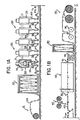
- FIG. 1A and 1B Illustrative apparatus for forming inlaid vinyl sheeting in accordance with the invention is depicted in Figs. 1A and 1B.
- the apparatus comprises an unwind stand 10, an accumulator 20, a plurality of printing stations 30, a second unwind stand 40, a knife edge coater 50, an oven 60, an embossing station 70, cooling cans 75, a second accumulator 80, a stock windup stand 90, and a release paper windup stand 95.
- Each of the printing stations 30 comprises a rotary screen printer 32, a hot air dryer 34, and a series of conveyors 36.
- the apparatus of Figs. 1A and 1B is used to perform a series of operations on a web of material 100 that is transported through this equipment.
- Each rotary screen printer 32 is used to deposit plugs of differently colored plastisols on the moving web and this plastisol is partially gelled by hot air from jets 38 in hot air dryer 34.
- the individual components of the apparatus depicted in Figs. 1A and 1B are old and will not be described in detail here. Their use, as detailed below, to make an inlaid vinyl sheeting having discrete plugs of differently colored plastisols is new.
- the inlaid vinyl sheeting is made by a plurality of passes through the equipment depicted in Figs. 1A and 1B. As shown in the cross section of Fig. 7, the inlaid vinyl sheeting is made of three layers: a backing 130, a decorative layer 135 and a wear coat 140.
- a web of release paper is guided from unwind station 10 through accumulator 20 and printing stations 30 to the rotary screen printer 32 of the last printing station where a first layer 145 of plastisol 6 to 8 mils (0.15 to 0.2 mm.) thick is deposited on the release paper.
- the type of screen and/or the viscosity of the plastisol are selected so that a continuous layer of plastisol is printed on the release paper.
- an open-mesh non-woven fiberglass web 150 is deposited by unwind stand 40 on top of the first plastisol layer; and a second layer 155 of plastisol 30 to 35 mils (0.76 to 0.89 mm.) thick is deposited on top of the fiberglass web. Because the fiberglass web is open mesh, it contributes little to the final thickness of the backing material which illustratively is about 40 to 45 mils (1.02 to 1.14 mm.).
- the web then enters an oven 60 where the P lasti- r sol layers are cured to form a substantially unitary, fiberglass reinforced plastisol-fiberglass-plastisol composition.
- the release paper is stripped away from the cured composition at windup stands 90 and 95; and the cured composition and the release paper are wound on separate rolls. The release paper may then be reused in the formation of other backings.
- the roll of backing is positioned in unwind stand 10.
- the web of backing is then fed through accumulator 20 and print stations 30; and at each printing station discrete plugs of plastisol of a different color are deposited thereon.
- the web is printed on the side of the backing that was originally in contact with the release paper; and the roll of backing is wound and unwound accordingly.
- Fig. 2 depicts a top view of an illustrative example of an inlaid vinyl sheeting 110 made in accordance with our invention.
- the decorative pattern in said sheeting comprises a plurality of first regions 112 representing an array of bricks with each brick separated by a second region 113 representing the mortar between the bricks.
- Illustrative examples of rotary screens 116 and 117 for printing portions of the mortar and brick patterns are depicted in Figs. 3A and 3B.
- each screen contains an array of small holes 119 through which a plastisol may be squeezed.
- a different such screen is mounted in each rotary screen printer 32 in a printing station 30 and the angular position of the screens are set so that the pattern printed by each screen is in register with the patterns printed by the other screens.
- FIG. 4 A side view of a rotary screen printer 32 is depicted in Fig. 4.
- a narrow tube 121 through which plastisol flows to the interior of the screen.
- a multiplicity of holes 123 in this tube permits the plastisol to flow out of the tube onto the inside surface of the screen.
- the plastisol is moved upwards against a squeegee 125 which is pressed tightly against the inside surface of the rotary screen. The squeegee forces the plastisol out through the holes in the screen onto the upper surface of the web of backing 130 that passes through each of the printing stations.
- Each plug of plastisol that is deposited on backing 130 is a three-dimensional solid with a shape approximately the shape of the hole through which it was squeezed and a height that is approximately the thickness of the screen.
- the screens used are stainless steel cylinders with cylindrical holes having a diameter on the order of 15 to 60 mils (0.38 to 1.52 mm.) and a thickness from 8 to 20 mils (0.20 to 0.51 mm.).
- Rotary silk screen printers are well known and do not of themselves form a part of this invention. Accordingly the details of construction and operation of the printer will not be discussed further.
- the backing Immediately after the plugs of plastisol are deposited on backing 130 at each printing station, the backing enters a hot air dryer 34 where the newly deposited plastisol is partially gelled.
- the plugs of colored plastisol deposited at each station are separately (- cured; and the different colors deposited at different stations remain distinct from one another. To a large extent, the individual plugs of the same color deposited at the same station also tend to remain distinct.
- the rotary screen at each of printing stations 30 defines approximately the same pattern depicted in Fig. 3A; but holes 119 in each of the five screens are in different relative positions. As a result each of the screens deposits discrete plugs of plastisol on different portions of backing 130.
- An enlarged illustrative segment of the mortar pattern that is deposited by the five printing stations is shown in Fig. 5.
- the first printing station deposits plugs A of plastisol having a first color
- the second printing station deposits plugs B having a second color
- the third station deposits plugs C having a third color
- the fourth station deposits plugs D having a fourth color
- the fifth station deposits plugs E having a fifth color.
- the plugs are adjacent to one another but, as depicted in Fig. 5, for the most part maintain their separate identity.
- the plugs of colored plastisol deposited by the five printing stations cover the entire surface of backing 130 so as to form a mortar layer 160 (Fig. 7) having a substantially uniform thickness on the order of 8 to 20 mils (0.20 to 0.51 mm.).
- the mortar pattern is printed on backing 120 and partially gelled at printing stations 30, it passes through oven 60 where it is further cured; and the web of backing 130 and mortar layer 160 is then wound on a roll in windup stand 90.
- each of the screens at each of printing stations 30 are replaced by rotary screens which have approximately the same pattern depicted in Fig. 3B but with holes 119 in each of the screens in different relative positions.
- the previously wound roll of backing and mortar layer is then transferred to unwind stand 10; and the web is again fed through accumulator 20 and print stations 30.
- each of the screens deposits discrete plugs of plastisols on different portions of mortar layer 160 to form a brick layer 165 (Fig. 7) which likewise has a substantially uniform thickness on the order of 8 to 20 mils (0.20 to 0.51 mm.).
- FIG. 6 A top view of an enlarged illustrative segment of the brick pattern that is deposited by the five printing stations is shown in Fig. 6; and a cross-section through this view on line 7-7 is shown in Fig. 7.
- the first printing station deposits plugs F of plastisol having a first color
- the second printing station deposits plug G of plastisol having a second color
- the third station deposits plugs H of plastisol having a third color
- the fourth station deposits plugs I of plastisol having a fourth color
- the fifth printing station deposits plugs J having a fifth color.
- the plugs are adjacent to one another but for the most part maintain their separate identity.
- the plastisol that defines the brick pattern is deposited on only portions of the underlying mortar layer 160 as shown in Fig. 7.
- an embossing effect is achieved by the printing operation such that portions of the decorative layer are only as thick as the mortar layer while other portions are as thick as the mortar and brick layers combined.
- the thickness of the design will be in register with the design with the minimum thickness being about 8 mils where there is only one layer atop the backing and about 16 mils where one layer of plugs of plastisol is deposited on top of another layer.
- a clear plastisol wear coat 140 is applied by a conventional knife coater 50 to the upper surface of decorative layer 135.
- the thickness of this coat is on the order of 10 mils (0.25 mm.) over brick layer 165 and is thicker over those portions of the pattern where there are no bricks.
- the wear coat and decorative layer are cured in oven 60. After curing they may be embossed, if desired, at embossing station 70.
- any embossing should be in register with the design in the decorative layer.
- Illustrative apparatus for embossing in register with a design is described in U.S. Patent No. 3,465,384 to Barchi, et al.
- At least one layer of plugs of colored plastisols should be printed on top of another layer to achieve three dimensional effects and to create the appearance of an inlaid vinyl sheeting made in accordance with the prior art using colored vinyl chips. It will, however, be apparent that this uses large amounts of pigmented plastisols which are relatively expensive. Accordingly, a less expensive inlaid vinyl sheeting may be prepared simply by printing each portion of the decorative pattern only on the backing. For example, with reference to the brick pattern illustrated in Fig. 2, the mortar pattern might be printed only on those portions of the backing that correspond to the spaces between the bricks in the final design. In such case the mortar pattern would be a open lattice.
- a plastisol is a thermoplastic resin in which fine particles are uniformly dispersed in plasticizer. When a plastisol is heated sufficiently to cure, it becomes a tough thermoplastic material. In the formation of sheeting materials, plastisols of vinyl choloride homopolymers and/or copolymers are conventionally used.
- the backing layer used in practicing the invention can be made with any conventional plastisol that can be deposited by a rotary screen to form a continuous layer.
- Such plastisols are widely used with rotary screens in the manufacture of sheeting materials.
- the pigmented plastisols must be formulated with care so that they will form discrete plugs of plastisol in the sheeting material.
- pigmented plastisol which may be used in the practice of the invention is formed by adding pigment to the following formulation of an unpigmented base plastisol:
- the Brookfield viscosity of the plastisol is adjusted to be about 25 to 35 poise, measured with a No. 4 spindle at 25 * C at 20 rpm.
- appropriate quantities of pigments such as black oxide 90-Q-1031, yellow oxide 20-Q-943, red oxide 40-Q-2113 and titanium dioxide 10-Q-672 available from Del Val Ink & Color Inc. may be added.
- Illustrative operating temperatures for the hot air dryers 34 of printing stations 30 are 270 to 290°F. (132 to 143°C.). At these operating temperatures the temperature of the plastisol rises to about 250°F. (121°C.) in the dryer. Illustrative operating temperatures for oven 60 are in the range of 320 to 380°F. (160 to 193"C.). In the course of oven curing, the temperature of the plastisol and wear coat rises to approximately 350°F. (177°C.).
- the invention may be practiced with a multiplicity of such layers.
- the minimum thickness of a layer of plugs of plastisol is about 8 mils, this is also the minimum thickness of decorative layer 135.
- the maximum thickness is a matter of choice depending on the design that is built up by the layers of plastisol plugs.
Landscapes
- Engineering & Computer Science (AREA)
- Textile Engineering (AREA)
- Printing Methods (AREA)
- Laminated Bodies (AREA)
- Application Of Or Painting With Fluid Materials (AREA)
- Synthetic Leather, Interior Materials Or Flexible Sheet Materials (AREA)
Applications Claiming Priority (2)
| Application Number | Priority Date | Filing Date | Title |
|---|---|---|---|
| US234402 | 1981-02-13 | ||
| US06/234,402 US4379185A (en) | 1981-02-13 | 1981-02-13 | Method for manufacture of inlaid vinyl-flooring |
Related Parent Applications (2)
| Application Number | Title | Priority Date | Filing Date |
|---|---|---|---|
| EP82900892A Division EP0071641B1 (fr) | 1981-02-13 | 1982-02-11 | Revetement de sol en vinyle et son procede de fabrication |
| EP82900892.9 Division | 1982-02-11 |
Publications (2)
| Publication Number | Publication Date |
|---|---|
| EP0182444A2 true EP0182444A2 (fr) | 1986-05-28 |
| EP0182444A3 EP0182444A3 (fr) | 1987-07-29 |
Family
ID=22881234
Family Applications (2)
| Application Number | Title | Priority Date | Filing Date |
|---|---|---|---|
| EP82900892A Expired EP0071641B1 (fr) | 1981-02-13 | 1982-02-11 | Revetement de sol en vinyle et son procede de fabrication |
| EP85201963A Withdrawn EP0182444A3 (fr) | 1981-02-13 | 1982-02-11 | Revêtement de sol marqueté en vinyle ainsi que son obtention |
Family Applications Before (1)
| Application Number | Title | Priority Date | Filing Date |
|---|---|---|---|
| EP82900892A Expired EP0071641B1 (fr) | 1981-02-13 | 1982-02-11 | Revetement de sol en vinyle et son procede de fabrication |
Country Status (8)
| Country | Link |
|---|---|
| US (1) | US4379185A (fr) |
| EP (2) | EP0071641B1 (fr) |
| JP (1) | JPS58500072A (fr) |
| CA (1) | CA1181920A (fr) |
| DE (1) | DE3276302D1 (fr) |
| IE (1) | IE53391B1 (fr) |
| MX (1) | MX159229A (fr) |
| WO (1) | WO1982002681A1 (fr) |
Families Citing this family (17)
| Publication number | Priority date | Publication date | Assignee | Title |
|---|---|---|---|---|
| DE3401588A1 (de) * | 1983-02-01 | 1984-08-02 | Molins PLC, London | Vorrichtung zum aufbringen von klebstoff |
| DE3433382A1 (de) * | 1984-09-12 | 1986-03-20 | Pegulan-Werke Ag, 6710 Frankenthal | Verfahren und vorrichtung zur kontinuierlichen beschichtung von kunststoff-bodenbelaegen mit strukturierter oberflaeche |
| FR2607055B1 (fr) * | 1986-11-20 | 1989-04-21 | Pennel Flipo | Nouveau tissu enduit a decor repere et son procede de fabrication |
| FR2722138B1 (fr) * | 1994-07-07 | 1996-09-20 | Bourrieres Francis | Pochoir de serigraphie et procede pour le realiser |
| DE4428670B4 (de) * | 1994-08-12 | 2004-04-01 | Giesecke & Devrient Gmbh | Rotations-Siebdruckzylinder |
| DE69605950T2 (de) * | 1995-02-01 | 2000-07-20 | Chromium Graphics, Inc. | Herstellungsverfahren einer Anzeige |
| US5802979A (en) * | 1995-02-01 | 1998-09-08 | Chromium Graphics | Method for manufacturing a display |
| JP3305192B2 (ja) * | 1995-03-15 | 2002-07-22 | セイコーエプソン株式会社 | 接着剤転写方法、及び転写装置 |
| US5645889A (en) * | 1995-06-07 | 1997-07-08 | Congoleum Corporation | Decorative surface coverings and methods for making |
| JP2000001041A (ja) * | 1998-06-12 | 2000-01-07 | Riso Kagaku Corp | 孔版印刷装置及び孔版印刷用版胴 |
| JP2000118113A (ja) * | 1998-10-15 | 2000-04-25 | Riso Kagaku Corp | 孔版印刷方法及び装置 |
| US6933036B2 (en) * | 2002-07-11 | 2005-08-23 | Textron Inc. | Non-skid floor mat design |
| GB0323462D0 (en) * | 2003-10-07 | 2003-11-05 | Fujifilm Electronic Imaging | Providing a surface layer or structure on a substrate |
| US20080067713A1 (en) * | 2004-12-14 | 2008-03-20 | Robert Bordener | Method of producing and business model for applying a thin laminate sheet of a decorative material |
| CA2500607A1 (fr) * | 2005-03-14 | 2006-09-14 | Heidi Eichenberger | Pellicule decorative et methode de fabrication |
| EP3091968B1 (fr) | 2013-12-31 | 2025-10-29 | Kenvue Brands LLC | Procès pour la fabrication d'un film formé de plusieurs couches |
| ES2909467T3 (es) * | 2013-12-31 | 2022-05-06 | Johnson & Johnson Consumer Inc | Proceso para formar un producto de película con forma |
Family Cites Families (18)
| Publication number | Priority date | Publication date | Assignee | Title |
|---|---|---|---|---|
| US278212A (en) * | 1883-05-22 | Manufacture of wall-paper | ||
| US2359825A (en) * | 1941-12-12 | 1944-10-10 | Solar Lab | Apparatus for decorating |
| NL254021A (fr) * | 1959-07-21 | 1900-01-01 | ||
| CH467378A (de) * | 1965-11-01 | 1969-01-15 | Freudenberg Carl Fa | Atmungsaktives Kunstleder |
| GB1142875A (en) * | 1966-06-23 | 1969-02-12 | Scott Bader Co | Improvements in or relating to wallpaper |
| US3589289A (en) * | 1966-12-22 | 1971-06-29 | Burroughs Corp | Printing members and methods for graphic composition |
| US3551269A (en) * | 1967-03-06 | 1970-12-29 | Owens Corning Fiberglass Corp | Glass fiber-plastic composites of improved strength |
| DE2034536A1 (fr) * | 1970-07-11 | 1972-02-03 | ||
| US3900641A (en) * | 1972-01-21 | 1975-08-19 | Lancaster Products Company | Method of forming decorator panels |
| FR2236657A1 (en) * | 1973-06-29 | 1975-02-07 | Bat Applic Revetement Plastiq | Composite cladding of partially transparent PVC - incorporating a printed cellulosic tissue to extend the decorative range |
| FR2249541A5 (fr) * | 1973-10-24 | 1975-05-23 | Duchenaud Alain | |
| CS166515B1 (fr) * | 1973-11-01 | 1976-02-27 | ||
| LU68838A1 (fr) * | 1973-11-21 | 1975-08-20 | ||
| US3973489A (en) * | 1974-10-31 | 1976-08-10 | Black James | Web printer |
| FR2305301A1 (fr) * | 1975-03-27 | 1976-10-22 | Carre Pierrat Ets | Materiau souple composite isothermique en forme de nappe et son procede de fabrication |
| US4038123A (en) * | 1976-02-27 | 1977-07-26 | Mach Iii, Inc. | Method for printing a color design on a release paper for heat transfer to a fabric material |
| LU79184A1 (fr) * | 1978-03-07 | 1979-10-29 | Eurofloor Sa | Procede de fabrication d'un revetement composite en relief et produits obtenus |
| CA1143614A (fr) * | 1978-04-14 | 1983-03-29 | Joseph C. Harkins, Jr. | Methode de production de feuilles a surface repoussee a partir de resines |
-
1981
- 1981-02-13 US US06/234,402 patent/US4379185A/en not_active Expired - Fee Related
-
1982
- 1982-02-10 CA CA000395991A patent/CA1181920A/fr not_active Expired
- 1982-02-11 EP EP82900892A patent/EP0071641B1/fr not_active Expired
- 1982-02-11 EP EP85201963A patent/EP0182444A3/fr not_active Withdrawn
- 1982-02-11 DE DE8282900892T patent/DE3276302D1/de not_active Expired
- 1982-02-11 JP JP57500957A patent/JPS58500072A/ja active Pending
- 1982-02-11 WO PCT/US1982/000172 patent/WO1982002681A1/fr not_active Ceased
- 1982-02-12 MX MX191380A patent/MX159229A/es unknown
- 1982-02-12 IE IE309/82A patent/IE53391B1/en unknown
Also Published As
| Publication number | Publication date |
|---|---|
| IE53391B1 (en) | 1988-11-09 |
| IE820309L (en) | 1982-08-13 |
| WO1982002681A1 (fr) | 1982-08-19 |
| EP0182444A3 (fr) | 1987-07-29 |
| CA1181920A (fr) | 1985-02-05 |
| JPS58500072A (ja) | 1983-01-13 |
| MX159229A (es) | 1989-05-08 |
| DE3276302D1 (en) | 1987-06-19 |
| EP0071641B1 (fr) | 1987-05-13 |
| EP0071641A1 (fr) | 1983-02-16 |
| US4379185A (en) | 1983-04-05 |
| EP0071641A4 (fr) | 1983-07-08 |
Similar Documents
| Publication | Publication Date | Title |
|---|---|---|
| EP0071641B1 (fr) | Revetement de sol en vinyle et son procede de fabrication | |
| US3810774A (en) | Multi-color,multi-patterned panels | |
| US5891564A (en) | Decorative surface coverings | |
| DE69619730T2 (de) | Dekorative Oberflächenbeläge und Verfahren zu deren Herstellung | |
| US5246765A (en) | Decorative inlaid types of sheet materials for commerical use | |
| DE3689566T2 (de) | Bedruckte einlegeblattmaterialien mit einmaligem dekoreffekt und deren herstellungsverfahren. | |
| EP0240559B1 (fr) | Procede de fabrication de materiaux en feuilles a incrustation | |
| DE2449567C2 (de) | Vorrichtung zum Auftragen reliefartiger Schichten auf einer Unterlage, insbesondere auf Fußboden- und Wandbekleidungen | |
| EP0522064B1 (fr) | Procede et produit d'incrustation de revetement de sol en vinyle | |
| US4158073A (en) | Process for producing decorative multi-level embossed surface covering | |
| US5260118A (en) | Materials having a selectively applied decorative adhesive matrix | |
| US3951714A (en) | Method of manufacturing a decorative floor covering | |
| US4496414A (en) | Method of forming a backing material | |
| CA1189435A (fr) | Methode de fabrication d'un materiau de support | |
| EP0506253A1 (fr) | Matériaux en feuilles incrustés possédant une matrice décorative adhésive, appliquée sélectivement | |
| DE3531716C2 (de) | Fußbodenbelag und Verfahren zu seiner Herstellung | |
| CN119947873A (zh) | 用于装饰陶瓷制品的设备和工艺 | |
| US2863245A (en) | Design roller | |
| US4207368A (en) | Decorative multi-level embossed surface covering | |
| US4552606A (en) | Flotation method for orienting chips in the manufacture of surface covering | |
| EP4221937A1 (fr) | Dispositif et procédé de revêtement d'une surface | |
| US7964053B2 (en) | Patterned linoleum sheeting | |
| US1726056A (en) | Ornamentation process and apparatus therefor | |
| EP4624189A1 (fr) | Procédé et dispositif de fabrication d'un stratifié, en particulier d'un stratifié dans une presse cpl dotée d'une structure synchrone décorative | |
| JPH04131238A (ja) | 型押し拭きとり化粧面被覆材及びその製作方法 |
Legal Events
| Date | Code | Title | Description |
|---|---|---|---|
| PUAI | Public reference made under article 153(3) epc to a published international application that has entered the european phase |
Free format text: ORIGINAL CODE: 0009012 |
|
| 17P | Request for examination filed |
Effective date: 19851212 |
|
| AC | Divisional application: reference to earlier application |
Ref document number: 71641 Country of ref document: EP |
|
| AK | Designated contracting states |
Kind code of ref document: A2 Designated state(s): BE DE FR GB NL SE |
|
| PUAL | Search report despatched |
Free format text: ORIGINAL CODE: 0009013 |
|
| AK | Designated contracting states |
Kind code of ref document: A3 Designated state(s): BE DE FR GB NL SE |
|
| 17Q | First examination report despatched |
Effective date: 19880705 |
|
| STAA | Information on the status of an ep patent application or granted ep patent |
Free format text: STATUS: THE APPLICATION IS DEEMED TO BE WITHDRAWN |
|
| 18D | Application deemed to be withdrawn |
Effective date: 19881116 |
|
| RIN1 | Information on inventor provided before grant (corrected) |
Inventor name: FERGUSON, DONALD CLAIR Inventor name: SMITH, MERRILL MARK |