EP0182459A2 - Arrangement d'étanchéité - Google Patents
Arrangement d'étanchéité Download PDFInfo
- Publication number
- EP0182459A2 EP0182459A2 EP85306124A EP85306124A EP0182459A2 EP 0182459 A2 EP0182459 A2 EP 0182459A2 EP 85306124 A EP85306124 A EP 85306124A EP 85306124 A EP85306124 A EP 85306124A EP 0182459 A2 EP0182459 A2 EP 0182459A2
- Authority
- EP
- European Patent Office
- Prior art keywords
- seal
- spaced
- construction
- opening
- sealing portions
- Prior art date
- Legal status (The legal status is an assumption and is not a legal conclusion. Google has not performed a legal analysis and makes no representation as to the accuracy of the status listed.)
- Granted
Links
Images





Classifications
-
- F—MECHANICAL ENGINEERING; LIGHTING; HEATING; WEAPONS; BLASTING
- F16—ENGINEERING ELEMENTS AND UNITS; GENERAL MEASURES FOR PRODUCING AND MAINTAINING EFFECTIVE FUNCTIONING OF MACHINES OR INSTALLATIONS; THERMAL INSULATION IN GENERAL
- F16L—PIPES; JOINTS OR FITTINGS FOR PIPES; SUPPORTS FOR PIPES, CABLES OR PROTECTIVE TUBING; MEANS FOR THERMAL INSULATION IN GENERAL
- F16L17/00—Joints with packing adapted to sealing by fluid pressure
- F16L17/02—Joints with packing adapted to sealing by fluid pressure with sealing rings arranged between outer surface of pipe and inner surface of sleeve or socket
- F16L17/025—Joints with packing adapted to sealing by fluid pressure with sealing rings arranged between outer surface of pipe and inner surface of sleeve or socket the sealing rings having radially directed ribs
-
- F—MECHANICAL ENGINEERING; LIGHTING; HEATING; WEAPONS; BLASTING
- F16—ENGINEERING ELEMENTS AND UNITS; GENERAL MEASURES FOR PRODUCING AND MAINTAINING EFFECTIVE FUNCTIONING OF MACHINES OR INSTALLATIONS; THERMAL INSULATION IN GENERAL
- F16J—PISTONS; CYLINDERS; SEALINGS
- F16J15/00—Sealings
- F16J15/16—Sealings between relatively-moving surfaces
- F16J15/32—Sealings between relatively-moving surfaces with elastic sealings, e.g. O-rings
- F16J15/3204—Sealings between relatively-moving surfaces with elastic sealings, e.g. O-rings with at least one lip
-
- F—MECHANICAL ENGINEERING; LIGHTING; HEATING; WEAPONS; BLASTING
- F16—ENGINEERING ELEMENTS AND UNITS; GENERAL MEASURES FOR PRODUCING AND MAINTAINING EFFECTIVE FUNCTIONING OF MACHINES OR INSTALLATIONS; THERMAL INSULATION IN GENERAL
- F16L—PIPES; JOINTS OR FITTINGS FOR PIPES; SUPPORTS FOR PIPES, CABLES OR PROTECTIVE TUBING; MEANS FOR THERMAL INSULATION IN GENERAL
- F16L17/00—Joints with packing adapted to sealing by fluid pressure
- F16L17/02—Joints with packing adapted to sealing by fluid pressure with sealing rings arranged between outer surface of pipe and inner surface of sleeve or socket
- F16L17/03—Joints with packing adapted to sealing by fluid pressure with sealing rings arranged between outer surface of pipe and inner surface of sleeve or socket having annular axial lips
- F16L17/035—Joints with packing adapted to sealing by fluid pressure with sealing rings arranged between outer surface of pipe and inner surface of sleeve or socket having annular axial lips the sealing rings having two lips parallel to each other
Definitions
- 3,918,726 relates to another flexible seal member having an insert membrane embodied therein to provide reinforcement of the balance of the flexible seal against deformation and resistance to abrasion.
- the disclosure of Shire and Newman U.S. Patent No. 3,695,639 is characterized by two generally ring shaped seals mounted in spaced side by side relationship at the end of a connector housing.
- the outer seal is generally circular in cross-section and includes a first leg, and a second smaller leg connected together by a web portion.
- the end of the connector tube is provided with formations for holding the seals in the housing.
- These formations may include first and second counterbores for positioning the inner seal in the end of the connector housing.
- the base of the second counterbore is normally in spaced relation to the inner side of the second leg to permit the legs of the inner seal to flex when a pipe mounted in the connector pivots or vibrates.
- annular rings The basic purposes of these annular rings is to maintain a tight seal over the wide range of temperatures and conditions encountered in use.
- the environment encountered is typically that found in the heating and air conditioning ducts of a modern commercial jet transport airplane.
- the individual lengths of connector tube are flexible due to thermal expansion and contraction, placing substantial and repeated stress on the ring seals.
- the present invention for the first time presents an integral annular seal which provides excellent sealing, high flexibility and resistance to abrasion.
- the seal of this invention is simpler to make and install in a connector and is believed to represent a significant advance over the seals of the prior art. It is to be expected that this new seal will be widely adopted by the commercial jet transport industry.
- the present invention comprises an integral ring-shaped seal adapted to be carried at the end of a connector housing and provide two spaced-apart sealing portions, said two spaced-apart sealing portions being connected by a web, and said two spaced-apart sealing portions together with said web providing therebetween an opening adapted to receive a flange located in proximity to the end of the connector housing, at least one of said two spaced-apart sealing portions having a cut-out axially disposed away from said opening to provide increased resiliency and wear resistance.
- This invention further comprehends the novel combination comprising telescoping connector housing sections one of which has an upstanding annular flange located in proximity to its open end, and an integral ring-shaped seal carried at the end of one of said connector housing, said seal having two spaced-apart sealing portions, said two spaced-apart sealing portions being connected by a web, and said two spaced-apart sealing portions together with said web providing therebetween an opening, said flange being received in said opening, at least one of said two spaced-apart sealing portions having a cut-out axially disposed away from said opening to provide increased resilency and wear resistance.
- Another feature of this invention is that the integral seal of this invention is held in position by one flange which is received in an opening of complementary size and shape within the seal, as stated above.
- a second or end flange is also provided, as shown in the drawings.
- the flanges are "L" shaped and are usually welded to the connector wall. The length of the leg of either or both "L" shaped flanges abutting the connector wall can be cut to any size before welding and thereby adjust the space between flanges to accommodate any desired size of seal to vary the spacing between flanges.
- This feature is highly desirable in providing a high degree of manufacturing flexibility and product variability from identical standard "L" shaped elements and is itself an improvement over the prior art.
- a related object of this invention is to provide a novel combination of connector sections and ring seal which is better adapted to manufacturing control and field use conditions.
- Section 12 has two inwardly directed annular flanges 14 and 16 which are affixed to the body of section 12.
- the integral annular sealing ring 18 has two spaced-apart portions 20 and 22 interconnected by web 24.
- the opening 26 is a cut-out 28 which is axially disposed from opening 26.
- the integral ring 18 is composed of an elastomer which is reinforced with a fiberous or filamentary material such as fiberglass.
- the entire ring 18 can be made in one molding operation.
- the engagement of flange 16 with opening 26 maintains the ring 18 in the proper position within the connector end over virtually any and all ranges of operating conditions.
- This structure has been found to be uniquely resistance of abrasion and wear as the connector ends 10 and 12 intergo flex due to thermal cycling and other stresses.
- the connector portions per se are normally made of titanium. However, the specific materials of construction do not bear on the present invention.
- the integral annular seal can have a variety of cross-sectional configurations including the embodiment wherein both portions which are interconnected by the web have axially disposed cut-out at opposite sides of the flange-receiving opening.
- the symmetrical configurations afford greater flexibility than the asymmetrical configurations.
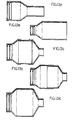
- Figures 7 to 12 illustrate the case where the flange-receiving opening and the axially displaced cut-out merge to form an L-shaped integral annular ring which has one leg adapted to abut the flange and the other leg adapted to abut the surface of one connector end on one of its sides and the free end of the flange on the other side.
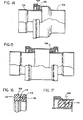
- Figures 14 through 22 relate to the structure wherein the connector ends 100 and 102 are telescoping.
- Connector end 100 has outwardly disposed flanges 104 and 106.
- the integral annular seal 108 has two spaced-apart portions 110 and 112 with interconnecting web 112.
- the space 114 is adapted to receive flange 106.
- the axially disposed cut-out 116 functions as described hereinabove.
- the present invention allows the use of the same general configuration of telescoping parts to be used in a compression or tension system, or a system that is mixed compression and tension.
- the connector can be used as an integral part of a duct or separately as a reducer.
Landscapes
- Engineering & Computer Science (AREA)
- General Engineering & Computer Science (AREA)
- Mechanical Engineering (AREA)
- Physics & Mathematics (AREA)
- Fluid Mechanics (AREA)
- Gasket Seals (AREA)
- Glass Compositions (AREA)
- Sealing Devices (AREA)
- Quick-Acting Or Multi-Walled Pipe Joints (AREA)
- Joints Allowing Movement (AREA)
Priority Applications (1)
| Application Number | Priority Date | Filing Date | Title |
|---|---|---|---|
| AT85306124T ATE44596T1 (de) | 1984-11-21 | 1985-08-29 | Dichtungsanordnung. |
Applications Claiming Priority (2)
| Application Number | Priority Date | Filing Date | Title |
|---|---|---|---|
| US673581 | 1984-11-21 | ||
| US06/673,581 US4565380A (en) | 1984-11-21 | 1984-11-21 | Seal with two sealing portions having flange receiving opening therebetween |
Publications (3)
| Publication Number | Publication Date |
|---|---|
| EP0182459A2 true EP0182459A2 (fr) | 1986-05-28 |
| EP0182459A3 EP0182459A3 (en) | 1986-08-06 |
| EP0182459B1 EP0182459B1 (fr) | 1989-07-12 |
Family
ID=24703235
Family Applications (1)
| Application Number | Title | Priority Date | Filing Date |
|---|---|---|---|
| EP85306124A Expired EP0182459B1 (fr) | 1984-11-21 | 1985-08-29 | Arrangement d'étanchéité |
Country Status (4)
| Country | Link |
|---|---|
| US (1) | US4565380A (fr) |
| EP (1) | EP0182459B1 (fr) |
| AT (1) | ATE44596T1 (fr) |
| DE (1) | DE3571488D1 (fr) |
Cited By (1)
| Publication number | Priority date | Publication date | Assignee | Title |
|---|---|---|---|---|
| CN106439021B (zh) * | 2016-11-18 | 2018-09-04 | 江苏智石科技有限公司 | 一种换热器密封圈 |
Families Citing this family (24)
| Publication number | Priority date | Publication date | Assignee | Title |
|---|---|---|---|---|
| DE3527213A1 (de) * | 1985-07-30 | 1987-02-12 | Witzenmann Metallschlauchfab | Verbindung zweier rohre einer leitung fuer heisse medien |
| US4762103A (en) * | 1986-08-25 | 1988-08-09 | General Motors Corporation | Engine with sealing head seat ring |
| DE3873072T2 (de) * | 1988-03-23 | 1992-12-03 | Cooper Ind Inc | Ventilschaftdichtung. |
| US5111879A (en) * | 1990-06-06 | 1992-05-12 | Amtrol Inc. | Sanitary locking lip split well seal |
| EP0563439B1 (fr) * | 1992-03-31 | 1996-01-03 | Firma Carl Freudenberg | Joint d'étanchéité pour tige coulissante |
| DE10106500A1 (de) * | 2001-02-13 | 2002-09-12 | Kludi Gmbh & Co Kg | Dichtungsring |
| US6905124B2 (en) * | 2001-08-15 | 2005-06-14 | Trostel Ltd. | Unitized seal for a gas spring |
| US7798497B2 (en) * | 2007-03-19 | 2010-09-21 | Freudenberg-Nok General Partnership | Tight package sensor seal |
| US20050173869A1 (en) * | 2004-02-09 | 2005-08-11 | Freudenberg-Nok General Partnership | Spark plug tube seal |
| US8002287B2 (en) * | 2004-02-09 | 2011-08-23 | Freudenberg-Nok General Partnership | Hand assemblable fuel injector seal |
| DE102005033650B4 (de) * | 2005-07-19 | 2017-06-14 | Resmed R&D Germany Gmbh | Atemmaskeneinrichtung und Verfahren zur Herstellung derselben |
| US20070180651A1 (en) * | 2006-02-06 | 2007-08-09 | Panasonic Corporation Of North America | Telescoping wand assembly with a flexible seal |
| EA013935B1 (ru) * | 2006-03-29 | 2010-08-30 | Бельхикаст Интернасьональ, С.Л.У. | Универсальная непроницаемая для жидкости манжета |
| US20090108536A1 (en) * | 2007-10-31 | 2009-04-30 | Freudenberg-Nok General Partnership | Actuator Seal |
| DE102007062662A1 (de) * | 2007-12-24 | 2009-06-25 | J. Eberspächer GmbH & Co. KG | Schiebesitz und Abgasbehandlungseinrichtung |
| CN101825177B (zh) * | 2010-05-07 | 2013-06-05 | 大全集团有限公司 | 密封圈 |
| EP2420706A1 (fr) * | 2010-08-20 | 2012-02-22 | Carl Freudenberg KG | Joint serré pour capteur d'emballage |
| DE102011081491A1 (de) | 2011-08-24 | 2013-02-28 | Endress + Hauser Flowtec Ag | L-Dichtring |
| US9309974B1 (en) * | 2012-02-23 | 2016-04-12 | PSI-Polymer Systems, Inc. | Seals for use with low to medium viscosity fluids and related methods, apparatuses and systems |
| US20130312846A1 (en) * | 2012-05-25 | 2013-11-28 | André Sloth Eriksen | Fluid connector for a cooling system |
| EP2884174B1 (fr) | 2012-08-07 | 2018-03-21 | Hino Motors, Ltd. | Brûleur |
| WO2014024944A1 (fr) | 2012-08-07 | 2014-02-13 | 日野自動車 株式会社 | Brûleur destiné à des dispositifs de purification de gaz d'échappement |
| US9243531B2 (en) | 2012-08-07 | 2016-01-26 | Hino Motors, Ltd. | Burner for exhaust gas purification devices |
| EP2884175A4 (fr) | 2012-08-13 | 2015-10-21 | Hino Motors Ltd | Brûleur |
Family Cites Families (9)
| Publication number | Priority date | Publication date | Assignee | Title |
|---|---|---|---|---|
| US2480116A (en) * | 1945-10-03 | 1949-08-30 | Brummer Olin | Oil seal means or the like |
| US2587405A (en) * | 1947-01-15 | 1952-02-26 | Sealol Corp | Seal for relatively rotating members |
| DE1121891B (de) * | 1956-07-23 | 1962-01-11 | Stabey Appbau Ges M B H | Dichtungsmanschette fuer druckbeaufschlagte Kolben |
| US3449021A (en) * | 1966-05-09 | 1969-06-10 | Conover & Co Inc C E | Low friction resilient sealing ring |
| US3563558A (en) * | 1968-11-04 | 1971-02-16 | Scovill Manufacturing Co | Piston seal with distortable ribs |
| DE1958378C3 (de) * | 1969-09-11 | 1974-04-11 | Pignone Sud S.P.A., Bari (Italien) | Druckluftregler |
| US3695639A (en) * | 1970-08-07 | 1972-10-03 | Gen Connector Corp | Connector |
| US3680874A (en) * | 1970-08-24 | 1972-08-01 | Federal Mogul Corp | Flexible pneumatic duct connectors assembled with internal seals |
| DE2947083C2 (de) * | 1979-11-22 | 1983-11-24 | Hoesch Werke Ag, 4600 Dortmund | Einsteckmuffenverbindung mit einem elastischen Dichtring für Stahlrohre |
-
1984
- 1984-11-21 US US06/673,581 patent/US4565380A/en not_active Ceased
-
1985
- 1985-08-29 AT AT85306124T patent/ATE44596T1/de active
- 1985-08-29 DE DE8585306124T patent/DE3571488D1/de not_active Expired
- 1985-08-29 EP EP85306124A patent/EP0182459B1/fr not_active Expired
Cited By (1)
| Publication number | Priority date | Publication date | Assignee | Title |
|---|---|---|---|---|
| CN106439021B (zh) * | 2016-11-18 | 2018-09-04 | 江苏智石科技有限公司 | 一种换热器密封圈 |
Also Published As
| Publication number | Publication date |
|---|---|
| ATE44596T1 (de) | 1989-07-15 |
| DE3571488D1 (en) | 1989-08-17 |
| EP0182459B1 (fr) | 1989-07-12 |
| EP0182459A3 (en) | 1986-08-06 |
| US4565380A (en) | 1986-01-21 |
Similar Documents
| Publication | Publication Date | Title |
|---|---|---|
| US4565380A (en) | Seal with two sealing portions having flange receiving opening therebetween | |
| USRE34874E (en) | Seal with two sealing portions having flange receiving opening therebetween | |
| US5468030A (en) | Tube clamp and coupling | |
| US5630593A (en) | Pressure-energized sealing rings | |
| US7883094B2 (en) | Offset stacked sealing system | |
| US4893847A (en) | Bearing seal for universal ball joint | |
| US4759555A (en) | Split ring seal with slip joint | |
| US6460897B1 (en) | Connector for flexible pipes having at least one resilient sealing ring | |
| US4589666A (en) | Slip joint assembly for a split ring seal | |
| KR940011855B1 (ko) | 파이프 커플링 | |
| US4121843A (en) | Multiple convolution sealing ring | |
| US4662598A (en) | Sleeve valve with integral control chamber | |
| US20020121744A1 (en) | Low leakage flexible cloth seals for turbine combustors | |
| US3695639A (en) | Connector | |
| US6296282B1 (en) | Articulated connecting element for piping elements | |
| US20040251639A1 (en) | Turbine spring clip seal | |
| US3129021A (en) | Flexible joint | |
| US4671541A (en) | Flexible pipe coupling | |
| CA2224986C (fr) | Ensemble joint et mecanisme de renfort associe | |
| US4548415A (en) | Articulated pipe joint seal assembly | |
| GB2323135A (en) | Pressure-energized sealing ring | |
| US20020117853A1 (en) | Quick connector | |
| US5112088A (en) | Duct joint link assembly | |
| EP0084538B1 (fr) | Assemblage d'etancheite dans un couplage de fluide | |
| EP1403584B1 (fr) | Joint de turbine de type pince à ressort |
Legal Events
| Date | Code | Title | Description |
|---|---|---|---|
| PUAI | Public reference made under article 153(3) epc to a published international application that has entered the european phase |
Free format text: ORIGINAL CODE: 0009012 |
|
| AK | Designated contracting states |
Kind code of ref document: A2 Designated state(s): AT BE CH DE FR GB IT LI LU NL SE |
|
| PUAL | Search report despatched |
Free format text: ORIGINAL CODE: 0009013 |
|
| AK | Designated contracting states |
Kind code of ref document: A3 Designated state(s): AT BE CH DE FR GB IT LI LU NL SE |
|
| 17P | Request for examination filed |
Effective date: 19870120 |
|
| 17Q | First examination report despatched |
Effective date: 19871117 |
|
| GRAA | (expected) grant |
Free format text: ORIGINAL CODE: 0009210 |
|
| AK | Designated contracting states |
Kind code of ref document: B1 Designated state(s): AT BE CH DE FR GB IT LI LU NL SE |
|
| PG25 | Lapsed in a contracting state [announced via postgrant information from national office to epo] |
Ref country code: SE Free format text: THE PATENT HAS BEEN ANNULLED BY A DECISION OF A NATIONAL AUTHORITY Effective date: 19890712 Ref country code: NL Effective date: 19890712 Ref country code: LI Effective date: 19890712 Ref country code: CH Effective date: 19890712 Ref country code: BE Effective date: 19890712 Ref country code: AT Effective date: 19890712 |
|
| REF | Corresponds to: |
Ref document number: 44596 Country of ref document: AT Date of ref document: 19890715 Kind code of ref document: T |
|
| REF | Corresponds to: |
Ref document number: 3571488 Country of ref document: DE Date of ref document: 19890817 |
|
| ET | Fr: translation filed | ||
| PG25 | Lapsed in a contracting state [announced via postgrant information from national office to epo] |
Ref country code: LU Free format text: LAPSE BECAUSE OF NON-PAYMENT OF DUE FEES Effective date: 19890831 |
|
| ITF | It: translation for a ep patent filed | ||
| REG | Reference to a national code |
Ref country code: CH Ref legal event code: PL |
|
| NLV1 | Nl: lapsed or annulled due to failure to fulfill the requirements of art. 29p and 29m of the patents act | ||
| PLBE | No opposition filed within time limit |
Free format text: ORIGINAL CODE: 0009261 |
|
| STAA | Information on the status of an ep patent application or granted ep patent |
Free format text: STATUS: NO OPPOSITION FILED WITHIN TIME LIMIT |
|
| 26N | No opposition filed | ||
| ITTA | It: last paid annual fee | ||
| REG | Reference to a national code |
Ref country code: GB Ref legal event code: IF02 |
|
| PGFP | Annual fee paid to national office [announced via postgrant information from national office to epo] |
Ref country code: GB Payment date: 20040901 Year of fee payment: 20 |
|
| PGFP | Annual fee paid to national office [announced via postgrant information from national office to epo] |
Ref country code: DE Payment date: 20040902 Year of fee payment: 20 |
|
| PGFP | Annual fee paid to national office [announced via postgrant information from national office to epo] |
Ref country code: FR Payment date: 20040908 Year of fee payment: 20 |
|
| PG25 | Lapsed in a contracting state [announced via postgrant information from national office to epo] |
Ref country code: GB Free format text: LAPSE BECAUSE OF EXPIRATION OF PROTECTION Effective date: 20050828 |
|
| REG | Reference to a national code |
Ref country code: GB Ref legal event code: PE20 |