EP0182469A1 - Appareil et procédé de la génération d'une métrologie de profil superficiel et de contours de surface en trois dimensions - Google Patents
Appareil et procédé de la génération d'une métrologie de profil superficiel et de contours de surface en trois dimensions Download PDFInfo
- Publication number
- EP0182469A1 EP0182469A1 EP85306523A EP85306523A EP0182469A1 EP 0182469 A1 EP0182469 A1 EP 0182469A1 EP 85306523 A EP85306523 A EP 85306523A EP 85306523 A EP85306523 A EP 85306523A EP 0182469 A1 EP0182469 A1 EP 0182469A1
- Authority
- EP
- European Patent Office
- Prior art keywords
- point
- phase
- incident beam
- determining
- detector
- Prior art date
- Legal status (The legal status is an assumption and is not a legal conclusion. Google has not performed a legal analysis and makes no representation as to the accuracy of the status listed.)
- Granted
Links
- 238000000034 method Methods 0.000 title claims description 47
- 238000001314 profilometry Methods 0.000 title description 5
- 238000005259 measurement Methods 0.000 abstract description 17
- 238000000847 optical profilometry Methods 0.000 abstract 1
- 238000010586 diagram Methods 0.000 description 19
- 230000003287 optical effect Effects 0.000 description 18
- 229910003460 diamond Inorganic materials 0.000 description 13
- 239000010432 diamond Substances 0.000 description 13
- 238000012545 processing Methods 0.000 description 11
- 238000003384 imaging method Methods 0.000 description 9
- 238000004458 analytical method Methods 0.000 description 7
- 238000009826 distribution Methods 0.000 description 7
- 238000013507 mapping Methods 0.000 description 7
- 230000010363 phase shift Effects 0.000 description 6
- 230000007704 transition Effects 0.000 description 6
- 230000006870 function Effects 0.000 description 5
- 238000005286 illumination Methods 0.000 description 5
- 238000005305 interferometry Methods 0.000 description 5
- 238000013459 approach Methods 0.000 description 4
- 230000008901 benefit Effects 0.000 description 4
- 238000002474 experimental method Methods 0.000 description 4
- 238000005070 sampling Methods 0.000 description 4
- 238000003860 storage Methods 0.000 description 4
- 230000005540 biological transmission Effects 0.000 description 3
- 210000003128 head Anatomy 0.000 description 3
- 238000013519 translation Methods 0.000 description 3
- 238000003491 array Methods 0.000 description 2
- 238000012937 correction Methods 0.000 description 2
- 230000000694 effects Effects 0.000 description 2
- 230000002093 peripheral effect Effects 0.000 description 2
- 230000010287 polarization Effects 0.000 description 2
- 210000001747 pupil Anatomy 0.000 description 2
- 239000007787 solid Substances 0.000 description 2
- 238000012360 testing method Methods 0.000 description 2
- 230000009466 transformation Effects 0.000 description 2
- 206010058907 Spinal deformity Diseases 0.000 description 1
- 230000008859 change Effects 0.000 description 1
- 238000006243 chemical reaction Methods 0.000 description 1
- 230000001427 coherent effect Effects 0.000 description 1
- 238000013481 data capture Methods 0.000 description 1
- 230000001419 dependent effect Effects 0.000 description 1
- 238000001514 detection method Methods 0.000 description 1
- 239000003814 drug Substances 0.000 description 1
- 230000014509 gene expression Effects 0.000 description 1
- 238000012812 general test Methods 0.000 description 1
- 230000000977 initiatory effect Effects 0.000 description 1
- 238000012886 linear function Methods 0.000 description 1
- 238000004519 manufacturing process Methods 0.000 description 1
- 238000012544 monitoring process Methods 0.000 description 1
- 230000000737 periodic effect Effects 0.000 description 1
- 238000003908 quality control method Methods 0.000 description 1
- 238000002310 reflectometry Methods 0.000 description 1
- 230000010076 replication Effects 0.000 description 1
- 238000011160 research Methods 0.000 description 1
- -1 robotics Substances 0.000 description 1
- 238000010008 shearing Methods 0.000 description 1
- 238000012876 topography Methods 0.000 description 1
Images







Classifications
-
- G—PHYSICS
- G01—MEASURING; TESTING
- G01B—MEASURING LENGTH, THICKNESS OR SIMILAR LINEAR DIMENSIONS; MEASURING ANGLES; MEASURING AREAS; MEASURING IRREGULARITIES OF SURFACES OR CONTOURS
- G01B11/00—Measuring arrangements characterised by the use of optical techniques
- G01B11/24—Measuring arrangements characterised by the use of optical techniques for measuring contours or curvatures
- G01B11/25—Measuring arrangements characterised by the use of optical techniques for measuring contours or curvatures by projecting a pattern, e.g. one or more lines, moiré fringes on the object
- G01B11/2518—Projection by scanning of the object
- G01B11/2527—Projection by scanning of the object with phase change by in-plane movement of the patern
Definitions
- This invention relates to the determination of the surface height of three-dimensional objects and, more particularly, to an improved apparatus and method of surface profilometry.
- This invention also relates to the determination of the surface contours of objects and, more particularly, to an improved apparatus and method for determining three dimensional surface profiles of objects, including 360 degree renditions thereof.
- An approach to obtaining a complete 360 degree view of a general three-dimensional object which has been the subject of intense activity, especially in computer vision research, is the reconstruction of three-dimensional shapes from several objects views, as seen from different points of observation. It generally involves the use of elaborate computer algorithms to 'match' these views in order to unify the images to determine the complete object shape.
- Such a digital image processing approach is computation intensive and generally offers limited accuracy.
- a form of the invention employs, inter alia, phase measuring techniques that have been used in classical interferometry, but are particularly advantageous for use in deformed grating profilometry.
- phase measuring techniques that have been used in classical interferometry, but are particularly advantageous for use in deformed grating profilometry.
- a sinusoidal intensity distribution is projected on a three dimensional diffuse surface
- the surface height distribution can be translated to a phase distribution, and the accuracy which is characteristic of phase modulation interferometry, can be used to advantage here.
- phase modulated frames of deformed grating image data by using several phase modulated frames of deformed grating image data, a high degree of precision in the phase measurement can be achieved.
- phase-measuring interferometry where phase values can be measured with a resolution of 1/1000 of a fringe period (versus 1/30 for conventional single frame interferometry), surface profile measurements with less than 10 micron resolution are possible by the use of an optical system with a projected grating pitch in the millimeter range.
- a complete 360 degree, or portion thereof, surface contour of an object can be obtained efficiently and with relatively inexpensive equipment, and without undue processing complexity, undue data acquisition and storage requirements, etc.
- a technique for determining a three-dimensional surface profile of an object An incident beam of light is directed at the object, the beam having a sinusoidally varying intensity pattern.
- the phase of the sinusoidal intensity pattern is modulated, such as by moving of a grating used to obtain the sinusoidally varying intensity pattern.
- a deformed grating image of a line profile of the object is detected, preferably at a linear detector; i.e., a detector having individual detector elements arranged in a line. For points on the line profile of the object, the distance of each such point from a reference line is then determined, each such
- a technique for determining the surface profile of a three-dimensional object.
- An incident beam of light having a sinusoidally varying intensity pattern, is directed at the object.
- the phase of the sinusoidal pattern of the incident beam is modulated.
- a deformed grating image of the object is received, at a detector array, for a number of different modulated phases of the input beam.
- the height of each point (i.e., elemental region) of the surface of the object is then determined with respect to a reference plane, each such height determination including the combining of the image intensity values at a detector position corresponding to a respective point of the object.
- the combined intensity values, for the object and for the reference plane are used to obtain an object phase for each point and a reference phase for each point.
- the difference between the object and reference phases for corresponding points is used in the height determination.
- a phase mapping as between object and reference phases is used in the height determination.
- distance determination including the step of combining intensity values of the received image at the different modulated phases to obtain an object phase for each point.
- the coordinate locations of the points on a line profile of the object can be determined.
- deformed grating images of the reference line are also obtained and used to obtain a reference phase for each point on the reference line, the reference phases then being used in the distance determinations of the object line profile coordinates with respect to the reference line.
- the object is then rotated by a rotational increment, and the above steps are repeated to obtain the distances from the reference line of the object points on the next line profile.
- This procedure can then be repeated, as the object is rotated by further rotational increments, to obtain the distance information (and coordinate information, if desired) for line profiles covering a full 360 degrees of rotation of the object.
- the data can be obtained in various procedural orders.
- the technique hereof has several advantages compared with other methods of 360-degree shape reconstruction.
- the invention does not involve any complex view-matching operations and is characterized by high measuring accuracy.
- the invention also lends itself more readily to complete automation without the need for major host system support.
- the main trade-off is a relatively low data acquisition rate, so the invention is preferably used for obtaining surface contours of stationary, rigid objects.
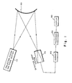
- FIG. 1 there is shown a block diagram of an apparatus in accordance with a first form of the invention and which can be used to practice the method of the invention.
- a sinusoidal grating projection system and phase shifter 110 is provided, and projects an optical beam at a three dimensional object 150.
- the reflected beam is received by a detector array system 120 which, in the illustrated embodiment detects frames of data which are stored in buffer 140 and processed by processor 150.
- the processor 150 may be, for example, any suitable analog or digital computer, processor, or microprocessor and conventional associated memory and peripherals, programmed consistent with the teachings hereof.
- a model LSI 11/23 made by Digital Equipment Corp., was utilized.
- the processed information can be displayed on a display device 160.
- a sinusoidal intensity distribution can be projected on the surface to be profiled, e.g. by generating an interference pattern between two coherent plane wavefronts or by projecting an image of a grating with sinusoidal transmission function distribution illuminated by an incoherent light source.
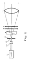
- Fig. 2 illustrates an embodiment of the projection system and phase shifter 110 (of Fig. 1), which comprises a laser illuminated shearing polarization interferometer.
- the linearly polarized output beam from the laser 111 is spatially filtered by filter 112, which includes lens 113 and pinhole 114, and then sheared by a Wollaston prism W.
- the phase modulator includes a combination of a quarter wave plate Q and a rotatable polarized P.
- the sinusoidal intensity distribution of the interference pattern can be modulated.
- a 180° rotation of the polarizer corresponds to a 2 ⁇ phase modulation and this permits precise phase shifts.
- phase shifters for example polarization dependent phase shifters such as electro-optic modulators, may also be used in this system.
- the fringe period can also be easily changed by an axial translation of the Wollaston prism W.
- a collimating lens L is used to conserve light and simplify the optical geometry.
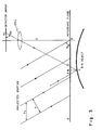
- the projected sinusoidal interferometric pattern has a period p o as seen on the reference plane, and the intensity that it produces at a point, such as C on the reference plane, is where a(x,y) is the background or DC light level, b(x,y) is the fringe contrast and O, the intersection of the imaging optical axis with the reference plane is assumed, for convenience, to coincide with an intensity maxima of the projected pattern.
- ⁇ R 2 ⁇ OC/p of the cosine function in Eq.
- (1) is defined as the "phase" at C and it effectively measures the geometric distance OC, if O is taken at the reference point where the phase is zero.
- An is one of the detectors in the array, located at the image plane and is used to measure the intensity at C on the reference plane and at D on the object.
- An imaging lens 120a, of the detection system 120, is shown in the Fig. 3 diagram. The intensity observed at D is the same as that which would have been observed at A on the reference plane, modified by the object reflectivity r(x,y), that is
- the difference ⁇ CD in phase values for the points C and D, observed by the same detector An can be related to the geometric distance AC as follows:
- AC is related to the surface height BD as follows: where the angles ⁇ o and ⁇ n are as shown in Fig. 3. Assuming that ⁇ n is nearly 90°, as is the case for any
- the projected pattern can be phase modulated by rotating the polarizer P (Fig. 2).
- ⁇ ' R is the phase angle reduced to the range 0 - 2 ⁇ and m is an integer. If ⁇ M represents the phase modulation, then from Eq. (1),
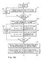
- the block 411 represents the setting of the initial phase of the incident beam of sinusoidally varying intensity; e.g., for example, to a reference phase designated as zero degrees.
- a frame of data (intensity information) is then collected and stored from the detector array to get a first set of intensity values for the object designated as I ol (x,y) values.
- a determination is then made (diamond 413) as to whether or not the last frame of the sequence has been collected and stored. If not, the block 414 is entered, this block representing the shifting of the phase of the incident beam, such as by rotating the polarizer (Fig. 2). In the present embodiment, three frames are used in the sequence, so there are two phase shifts of 120 degrees each.
- phase shifting can be implemented automatically under computer control, semiautomatically, or manually, as desired. Accordingly, at the completion of the loop 415, three frames of intensity values for the object, Ion (x,y) are obtained, as follows:
- the procedure of loop 415 is then repeated for the reference plane, as represented by the block 420.
- This data can be obtained, for example, by placing a white reflective reference plane adjacent the object, as illustrated in Fig. 3, and following the procedure just described to obtain frames of reference intensity values I rn (x,y) as follows:
- the data could alternatively be taken in any desired sequence, such as by interposing the reference plane before each phase shift so as to obtain both the object and reference intensity information at each incident beam phase, although this is not preferred.
- the reference phase information can be computed without taking measured reference data (from the known characteristics of the incident beam and the known system geometry), but it is preferable, when possible, to obtain the reference data from an actual reference plane so as to minimize the effects of distortions in the system, etc.
- the reference plane phase ⁇ ' r (x,y) at the point can be computed, using (8) above, from the three reference plane intensities as: as represented by the block 431.
- the block 432 is then entered, this block representing the computation, for point (x,y) of the object phase from the three object intensity measurements as:
- the block 441 is then entered.
- This block represents the procedure of assigning, for each point (x,y) the appropriate integer m (see equation (6)) by tracing the number of fringes on the reference plane image, where m is the fringe number, and then the determination of the reference plane phase for each such point.
- the block 442 represents the same operation for each point of the object.
- Fig. 12 is a flow diagram of a routine as represented by the blocks 441 and 442 for tracing the deformed grating fringes in order to assign appropriate m integer values, so that the object and reference phases ⁇ o (x,y) and 4 r (x, y ), respectively, can be obtained from ⁇ ' o (x,y) and ⁇ ' r (x,y).
- a y coordinate index is initialized (block 1211), m is initialized at zero (block 1212), and the x index is also intialized (block 1213). Processing then proceeds on a line-by-line basis along the x direction. For a given line, at each point, the previously computed phase value (for the object phase or the reference plane phase, depending on which one is being processed), the phase at each point is compared to the phase at the previous point, as represented by the diamond 1220. The adjacent phase values are compared by determining when there is a transition over a 2 ⁇ value, and the sign of the transition is also noted. The sign will depend on the slope of the object profile.
- Blocks 1221 and 1222 are then utilized to decrement or increment m, depending upon the sign of the transition, and the block 1225 is then entered. Also, if there was no transition at the point being examined, the block 1225 is entered directly. The block 1225 then represents the computation of the reference plane or object phase value (as the case may) in accordance with relationship (6).
- the x index is then tested (diamond 1230) and incremented (block 1231), and the loop 1232 continues for processing of an entire line in the x direction on the detector array. When the line is complete, the y index is tested (diamond 1240) and incremented (block 1241) and the loop 1233 is continued until all lines of points have been processed.
- the block 451 represents the selection of the first point (x,y) for height computation.
- the phase difference between the object and reference planes is computed in accordance with: as represented by the block 452.
- the distance AC (Fig. 3) can then be computed (block 453) from
- the block 454 represents the conversion into height BD, which is defined as h(x,y) in accordance with equation (5) as
- h(x,y) can then be stored for display or other use, as represented by the block 456. Inquiry is then made (diamond 457) as to whether or not the last point has been processed and, if not, the point being processed is incremented (block 458) and the loop 459 continues as the height values h(x,y) are obtained and stored for each point.
- Figs. 1,2 Profile measurements were made, using the system of Figs. 1,2, on a general test object (a half cylinder with two sections having different radii), mounted on a reference plane and illuminated with a sinusoidally varying beam intensity as previously described.
- a general test object a half cylinder with two sections having different radii
- Fig. 5 shows the deformed grating as seen by the detector array.
- Three images each were recorded for the reference plane and the object surface, with a phase increment of 120° of the projected fringe pattern following each recording, and processing was performed as previously described.
- Fig. 6 shows part of the surface profile plot, which was generated by displaying h(x,y) using a graphics plotter. The two sections of the object with different radii and the transition region are seen. The values obtained were very close to those measured using a contact profilimeter.
- the collimated laser illumination is replaced by the projected image of a translatable white light illuminated sinusoidal transmission grating.
- This system requires generally less expensive hardware than the previously described embodiment, and is more capable of handling large objects.
- the analysis of this system because of the divergent nature of the illumination and because the optical axes of the projection and imaging systems are not necessarily parallel, is somewhat more complicated.
- a buffer, processor, display and projection and imaging lenses are provided, as in the previous embodiment.
- the optical geometry of the projection and recording systems is represented in Fig. 7.
- P 1 and P 2 are the centers of the entrance and exit pupils of the projection optics.
- I 1 and 1 2 are the centers of the exit and entrance pupils of the imaging optics.
- G is a grating with pitch p and a sinusoidal intensity transmission.
- D c is one element of the image sensing array.
- the intensity variation along x on the reference plane can be described by the equation: where a(x,y) is the background or DC light level and b(x,y) is the fringe contrast.
- the phase ⁇ in this case is a non linear function of x because of the divergent nature of the image forming rays.
- every point on the reference plane is characterized by a unique phase value.
- the point C observed by the detector D of the array, has where m is an integer and 0 ⁇ ⁇ ' c ⁇ 2 ⁇ .
- the detector array samples the reference plane (as well as the object) and is again used to measure the phase at the sampling points by a phase shifting technique .
- N frames of intensity data are recorded and after each frame the grating G is translated by a distance p o /N. If I 1 , I 2 , Vietnamese IN are the intensity measurements for a point such as C, then, as previously described
- phase function is continuous, it is possible, as previously described, to determine m in equation (10) by detecting sharp phase changes of nearly 2 ⁇ which occur between two neighboring sample points, whenever a complete grating period has been sampled.
- a particular detector such as D c can measure the phase ⁇ c at a point C on the reference plane as well as ⁇ D on the point D of the object.
- C is a known detector location and the position of A, which in general would lie between two sampling points, can be located by linear interpolation using known phase values.
- the object height is where d and l o are distances as shown in Fig. 7.
- equation (12) can be simplified:
- h(x,y) is the object height at the x coordinate corresponding to B and not C. From known system geometrical parameters, one can calculate the distance BC and thus determine the x coordinate corresponding to the point B.
- the block 810 represents the collecting and storing of three frames of reference plane and object data in a manner similar to that previously described in conjunction with the loop 415 of Fig. 4.
- the phase shifting will be implemented by translation of the grating G.
- the three arrays of object intensity values can be represented as and the three arrays of reference plane intensity values can be represented as
- the object phase ⁇ ' o is then computed from and the reference phase Or is computed in accordance with These functions are represented by the blocks 831 and 832, and are consistent with the equation (11) above.
- the loop 835 then continues, in similar manner to that previously described in conjunction with Fig. 4, to obtain the reference and object phases for all desired points (x,y), diamond 833 and block 834 being used in the loop in the manner previously set forth.
- the appropriate integer m (see equation (10)) is obtained by tracing the number of fringes on the reference plane image, where m is the fringe number, and the reference plane phase for each such point is then determined.
- the block 842 represents the same operation for each point of the object. Reference can again be made to Fig. 12, and the accompanying description above, for the manner in which the resultant phases 4 r (x,y) and ⁇ o (x,y) are obtained.
- Fig. 8B includes the phase mapping portion of the routine.
- a first point is selected for phase mapping, as represented by the block 851.
- the phase ⁇ o (x,y) is compared to the phases of the sampling points on the reference plane, so as to locate point A on the reference plane which has the same phase.
- the geometric distance AC, between the points having the same phase is then determined in terms of detector element spacings (block 853).
- the object height can then be computed (equation (12)) as: as represented by the block 854. Alternatively, as described above, equation (13) could be used in some situations.
- suitable calibration factor and geometric correction can then be applied, and the height h(x,y) is stored, as represented by block 856.
- Inquiry is then made (diamond 857) as to whether or not the last point has been processed. If not, the point to be processed is incremented (block 858), and the loop 859 is continued to completion.
- sinusoidal gratings were generated by photographing out of focus a square wave grating pattern.
- a conventional slide projector was modified in order to operate with a grating slide, mounted on a stepper motor driven translation stage.
- the period of the projected grating measured on the reference plane, close to the optical axis of projection, was about 15 mm.
- Deformed grating images were recorded on a 128 X 128 photodiode array detector. Phase measurement was by a three discrete phase shift implementation of equation (11), and processing was in accordance with the routine previously described.
- Fig. 9 The results of a calibration experiment, using a cylindrical test object, which had been measured by a mechanical contact profilometer, are shown in Fig. 9.
- the line profile was generated using the experimental optical system and the 'X' marks indicate measurements made by a manual contact profilometer. An agreement of better than 1% between the measurements was observed, except in the regions with steep slopes where mechanical contact methods are not very reliable.
- FIG. 10 shows the deformed grating produced by this object.
- Fig. 11 is a graphical representation of the results obtained with the optical system and shows 97 profile lines with 87 points on each line. This object was approximately 150 mm wide and the depth at the tip of the nose measured from a reference plane was about 100 mm. In order to obtain a complete shadow free illumination of such objects and obtain a large angular field of view, two or more projected gratings may be used.
- a complete 360 degree view, or a desired portion thereof, of a three-dimensional object is obtained with minimal complication and processing.
- Fig. 13 which, like Fig. 7, employs a projected image of a translatable white light illuminated translatable grating, G.
- the projection and imaging optics are respectively represented in the Figure by lenses 1301 and 1302.
- a linear detector array 1350 for example a photodiode array, is provided.
- a three-dimensional object 1310, a mannequin head in the illustration, is mounted on rotatable table 1315 which is driven in rotation increments using motor 1320 which, in the present embodiment, is under control of a processor (to be described).
- the relative rotation as between the optical system and the object can be implemented by any suitable means and, if desired, the optical system can even be rotated around the object, although this is usually less preferred.
- the sinusoidal grating is projected onto the object and the resulting deformed grating is reimaged onto the linear detector array 1350.
- the distance h which in this case is the distance of an object point D from a reference line, when determined for each vertical (y) position, gives the object profile in the slice defined by the Y-Z plane. This is a "line profile of the object surface at the slice taken at a rotational angle 8 (Fig. 13b).
- every h-value obtained corresponds to the radial distance ⁇ r of a general point P from a reference virtual cylinder of radius R, as shown in Fig. 13b.
- the complete 3-D object data can be obtained through a 360 degree rotation of the object, and can be expressed in terms of ⁇ r(Y, ⁇ ) in cylindrical coordinates.
- a general object point P can be represented in relation to a global system of coordinates X, Y, Z using the transformation
- ⁇ r for a given line profile corresponding to a 0 value, are obtained using the following procedure: Three frames of line intensity data, I 1 , I 2 , and 1 3 are recorded for three grating positions phase-shifted by 2w/3. Three frames of line intensity data are also determined for the reference line. [This only need be done once, since the reference line is the same for all profiles. Again, the reference data can be computed without direct measurement, if desired.] Next, Ar (or h) is determined by using a phase-mapping technique, as was described above. A particular detector in the linear array 1350 measures the phase ⁇ C at point C on the reference line as well as Phase ⁇ D at the corresponding point D on the object.
- ⁇ R or h is determined from relationship (12) above, i.e. where distances d and l o are as shown in Fig. 13a.
- the object is then stepped to the next rotational angle, e, and the next line profile is obtained.
- the data can all be obtained before line profiles are computed or, alternatively, line profile computations can be made between taking data or contemporaneous therewith.
- the data for each line profile can be taken for a first phase of the incident beam, and then the grating shifted and the data again taken for the second and then the third phases of the incident beam.
- the Ar values can be inserted into equations (14) and (15) to obtain the governing equations for a general point description as follows:
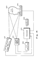
- Fig. 14 shows a block diagram of an embodiment of an apparatus in accordance with the invention.
- a sinusoidal grating projection system and phase shifter 1410 is provided, and projects an optical beam at a three dimensional object 1450, which is mounted on rotary stage 1490.
- the grating projector and phase shifter 1410 includes a source of white light illumination, a movable sinusoidal grating (e.g. G of Fig. 13a) and a projection optical (e.g. 1301 of Fig. 13a).
- the rotary stage 1490 may comprise a rotatable table 1315 and processor-controlled motor 1320, as shown in Fig. 13a.
- a linear camera array 1420 includes imaging optics (e.g. 1302 in Fig.
- a linear detector array e.g. 1350-m of Fig. 13a
- the linear detector array may alternately be implemented by scanning one line of a two dimensional array.
- Information from camera 1420 is digitized by analog-to-digital converter 1460, and the resultant digital signals are coupled to processor 1470.
- the processor may be for example any suitable digital or analog (in which case no A/ D would be required) computer, processor, or microprocessor and associated memory and peripherals, programmed consistent with the teachings hereof, a Digital Equipment Corp. Model LSI11/23 having been employed in one implementation.
- the processed information can be displayed on a display device 1480.
- FIG. 15 there is shown a flow diagram of the routine for the processor 1470 of the Fig. 13 embodiment, utilized to obtain data from which line profiles of an object are generated.
- the block 1511 represents the initiation of the system at an initial rotation angle, 8.
- the block 1512 is then entered, this block representing the collection and storage of three lines of object data for the current line profile (or slice), at rotation position 8. This is done, for example, by storing the intensity value obtained at each detector element of the linear detector, shifting the grating G to obtain a phase shift of 2iC/3, whereupon another line of data is taken at the detector elements and stored; followed by another phase shift of 2 ⁇ /3, and collection and storage of data.
- inquiry is made (diamond 1513) as to whether or not the last angle 8 has been processed; i.e., whether or not a full 360 degrees of rotation increments has been implemented, in the present example. If not, rotation to the next increment is implemented (block 1514), and the loop 1520 is continued, as a full set of data is obtained and stored.
- a reference plane can then be interposed (e.g., automatically or manually) and the collection and storage of three lines of reference data, for the three different reference phases, is obtained and stored in the same manner, as represented by the block 1513. Since the reference plane (which, when detected by the linear detector array, can be considered as a reference line) does not change, this data is taken only once.
- the object data is taken and stored continuously, although it will be understood that processing can be implemented, if desired, during the data acquisition mode; for example, by processing each line profile after the data is taken for said line profile (either before the data is taken for the next line profile, or contemporaneously therewith, such as on a time- sharing basis). Also, as previously indicated, a full set of data can be taken at a first phase of the incident beam, followed by repeats at second and third phases of the incident beam.
- FIG. 16 there is shown a flow diagram of the routine for obtaining the object phase ⁇ ' o (y, ⁇ ) and the reference phase ⁇ ' r (y, ⁇ ) for each point y of each line profile (at reference angle 8), from the data taken in the routine of Fig. 14.
- the block 1511 represents the initialization to the first line profile (at initial angle 8, and the first point, y).
- the object phase ⁇ ' o is then computed, using the relationship of equation (11), as:
- Inquiry is then made (diamond 1513) as to whether or not the last point, y, of the current line profile has been processed. If not, the point index is incremented (block 1514) to the next point y of the current line profile, and the loop 1520 is continued until all values of ⁇ ' o (y, ⁇ ) for the current line profile are obtained.
- the inquiry of diamond 1513 is answered in the affirmative, the diamond 1531 is entered, and inquiry is made as to whether or not the last line profile has been processed.
- the rotation angle index e is incremented (block 1532), and the phases are obtained for each point y for the next line profile reference angle 9 (via loop 1520), and the loop 1540 continues until all of the phase values ⁇ ' o (y, ⁇ ) have been obtained.
- the reference point index is initialized to the first point y (block 1551), and the reference phase ⁇ ' r (y) is obtained using the relationship: as represented by the block 1552.
- the loop 1560 then continues, in a manner similar to that just described with respect to the object phase computations, with the point index y being incremented (block 1554) and the loop continuing until the inquiry of diamond 1553 indicates that the reference phases have been obtained for all points y of the reference line.
- the values represent the component of the phase + that is between 0 and 2 ⁇ (e.g. equation (10) above), and that f can be obtained from where it can be determined, as previously described, by detecting sharp phase changes of nearly 2 ⁇ which occur between two neighboring sample points, whenever a complete grating period has been sampled.
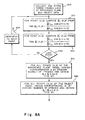
- the block 1711 represents the determination of the ⁇ ' o (y, ⁇ ) values from the previously obtained values of ⁇ ' o (y, ⁇ ) by obtaining a value of m for each point, using the routine of Fig. 12.
- the block 1712 represents the same operation, but in this case the values ⁇ r (y) are obtained for each point y of the reference line; again, by assigning values of small m by tracing fringes, using the routine of Fig. 12.
- the block 1713 represents the use of a mapping routine (of the type shown in Fig. 8B) to determine the geometric distance AC in terms of detector spacings.
- a 128 by 128 photodiode array was employed and a single column of data was read out and then processed as previously described.
- a mannequin head was again chosen as a test object.
- the object was rotated through 360-degrees in step increments of 2-degrees, resulting in a total of 128X180 sampling points.
- the final results were displayed on a graphics monitor and recorded on a high-resolution plotter.
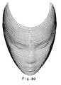
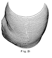
- Fig. 18 shows the 180 line profiles that were obtained for the mannequin head, directly from the raw data.
Landscapes
- Engineering & Computer Science (AREA)
- Computer Vision & Pattern Recognition (AREA)
- Physics & Mathematics (AREA)
- General Physics & Mathematics (AREA)
- Length Measuring Devices By Optical Means (AREA)
Applications Claiming Priority (4)
| Application Number | Priority Date | Filing Date | Title |
|---|---|---|---|
| US06/650,824 US4641972A (en) | 1984-09-14 | 1984-09-14 | Method and apparatus for surface profilometry |
| US650824 | 1984-09-14 | ||
| US06/753,722 US4657394A (en) | 1984-09-14 | 1985-07-10 | Apparatus and method for obtaining three dimensional surface contours |
| US753722 | 1985-07-10 |
Publications (2)
| Publication Number | Publication Date |
|---|---|
| EP0182469A1 true EP0182469A1 (fr) | 1986-05-28 |
| EP0182469B1 EP0182469B1 (fr) | 1990-11-28 |
Family
ID=27095944
Family Applications (1)
| Application Number | Title | Priority Date | Filing Date |
|---|---|---|---|
| EP85306523A Expired - Lifetime EP0182469B1 (fr) | 1984-09-14 | 1985-09-13 | Appareil et procédé de la génération d'une métrologie de profil superficiel et de contours de surface en trois dimensions |
Country Status (4)
| Country | Link |
|---|---|
| US (1) | US4657394A (fr) |
| EP (1) | EP0182469B1 (fr) |
| CA (1) | CA1261656A (fr) |
| DE (1) | DE3580740D1 (fr) |
Cited By (18)
| Publication number | Priority date | Publication date | Assignee | Title |
|---|---|---|---|---|
| DE3813692A1 (de) * | 1987-04-30 | 1988-11-17 | Eastman Kodak Co | Verfahren und vorrichtung zur digitalen moireprofilometrie, geeicht fuer die genaue umwandlung von phaseninformation in abstandsmessungen in einer vielzahl von richtungen |
| WO1988002847A3 (fr) * | 1986-10-15 | 1989-07-13 | Eastman Kodak Co | Mesure du contour de surfaces par des techniques de moirage a plage etendue |
| EP0262089A3 (fr) * | 1986-09-23 | 1989-08-09 | KERN & CO. AG Werke für Präzisionsmechanik Optik und Elektronik | Dispositif pour mesurer la surface d'un objet |
| WO1990007691A1 (fr) * | 1988-12-23 | 1990-07-12 | Klaus Pfister | Procede et dispositif d'observation de moirures sur des surfaces a examiner par moirage a dephasage |
| US5003187A (en) * | 1989-01-17 | 1991-03-26 | Kern & Co., Ag | Method and apparatus for surveying the surface of an object by projection of fringe patterns |
| US5076698A (en) * | 1988-11-09 | 1991-12-31 | Anstalt Gersan | Sensing the shape of an object |
| FR2664378A1 (fr) * | 1990-07-03 | 1992-01-10 | Bertin & Cie | Appareil de projection et de prise d'images pour la determination de la forme tridimensionnelle d'un objet. |
| EP0470816A1 (fr) * | 1990-08-08 | 1992-02-12 | Industrial Technology Institute | Système moiré à décalage de champ |
| US5206699A (en) * | 1988-05-06 | 1993-04-27 | Gersan Establishment | Sensing a narrow frequency band of radiation and gemstones |
| EP0534284A3 (en) * | 1991-09-26 | 1993-10-06 | Hans Dr. Steinbichler | Method and device for determining the absolute coordinates of an object |
| EP0563829A3 (en) * | 1992-03-30 | 1994-08-24 | Sharp Kk | Device for inspecting printed cream solder |
| WO1995017644A1 (fr) * | 1993-12-21 | 1995-06-29 | United Technologies Corporation | Systeme de mesure de contours |
| EP0769674A3 (fr) * | 1995-10-17 | 1998-01-07 | Aluminum Company Of America | Analyse des franges électroniques pour la détermination de contours de surfaces |
| RU2148793C1 (ru) * | 1999-02-19 | 2000-05-10 | Филиппов Евгений Иванович | Способ измерения формы и пространственного положения поверхности объекта |
| WO2001006210A1 (fr) * | 1999-07-14 | 2001-01-25 | Solvision Inc. | Procede et systeme de mesure du relief d'un objet |
| WO2003073044A1 (fr) * | 2002-02-28 | 2003-09-04 | Ckd Corporation | Instrument de mesure tridimensionnelle |
| US7079666B2 (en) | 2000-03-24 | 2006-07-18 | Solvision Inc. | System for simultaneous projections of multiple phase-shifted patterns for the three-dimensional inspection of an object |
| US9142025B2 (en) | 2011-10-05 | 2015-09-22 | Electronics And Telecommunications Research Institute | Method and apparatus for obtaining depth information using optical pattern |
Families Citing this family (73)
| Publication number | Priority date | Publication date | Assignee | Title |
|---|---|---|---|---|
| US4709156A (en) * | 1985-11-27 | 1987-11-24 | Ex-Cell-O Corporation | Method and apparatus for inspecting a surface |
| US4842411A (en) * | 1986-02-06 | 1989-06-27 | Vectron, Inc. | Method of automatically measuring the shape of a continuous surface |
| FR2610821B1 (fr) * | 1987-02-13 | 1989-06-09 | Hennson Int | Procede de prise d'empreinte medicale et dispositif pour sa mise en oeuvre |
| US4846577A (en) * | 1987-04-30 | 1989-07-11 | Lbp Partnership | Optical means for making measurements of surface contours |
| US4825263A (en) * | 1987-06-02 | 1989-04-25 | University Of Medicine & Dentistry Of New Jersey | Optical method and apparatus for determining three-dimensional changes in facial contours |
| CA1313040C (fr) * | 1988-03-31 | 1993-01-26 | Mitsuaki Uesugi | Methode et dispositif de mesure dans les trois dimensions d'objets a surface courbe |
| US4979815A (en) * | 1989-02-17 | 1990-12-25 | Tsikos Constantine J | Laser range imaging system based on projective geometry |
| US5121334A (en) * | 1989-06-08 | 1992-06-09 | Regents Of The University Of Minnesota | Method and apparatus for automated machining of objects of complex and unique geometry |
| US5184306A (en) * | 1989-06-09 | 1993-02-02 | Regents Of The University Of Minnesota | Automated high-precision fabrication of objects of complex and unique geometry |
| US5128870A (en) * | 1989-06-09 | 1992-07-07 | Regents Of The University Of Minnesota | Automated high-precision fabrication of objects of complex and unique geometry |
| US5257203A (en) * | 1989-06-09 | 1993-10-26 | Regents Of The University Of Minnesota | Method and apparatus for manipulating computer-based representations of objects of complex and unique geometry |
| US5027281A (en) * | 1989-06-09 | 1991-06-25 | Regents Of The University Of Minnesota | Method and apparatus for scanning and recording of coordinates describing three dimensional objects of complex and unique geometry |
| US4984893A (en) * | 1989-12-01 | 1991-01-15 | Wyko Corporation | Phase shifting device and method |
| US5347454A (en) * | 1990-04-10 | 1994-09-13 | Mushabac David R | Method, system and mold assembly for use in preparing a dental restoration |
| US5224049A (en) * | 1990-04-10 | 1993-06-29 | Mushabac David R | Method, system and mold assembly for use in preparing a dental prosthesis |
| US5569578A (en) * | 1990-04-10 | 1996-10-29 | Mushabac; David R. | Method and apparatus for effecting change in shape of pre-existing object |
| US5562448A (en) * | 1990-04-10 | 1996-10-08 | Mushabac; David R. | Method for facilitating dental diagnosis and treatment |
| US5545039A (en) * | 1990-04-10 | 1996-08-13 | Mushabac; David R. | Method and apparatus for preparing tooth or modifying dental restoration |
| US5343391A (en) * | 1990-04-10 | 1994-08-30 | Mushabac David R | Device for obtaining three dimensional contour data and for operating on a patient and related method |
| US5257184A (en) * | 1990-04-10 | 1993-10-26 | Mushabac David R | Method and apparatus with multiple data input stylii for collecting curvilinear contour data |
| US5133601A (en) * | 1991-06-12 | 1992-07-28 | Wyko Corporation | Rough surface profiler and method |
| US5313265A (en) * | 1992-03-02 | 1994-05-17 | Hughes Aircraft Company | Non-contact non-destructive latent image scanner |
| US5570186A (en) * | 1992-04-28 | 1996-10-29 | Mtu Motoren- Und Turbinen-Union Munich Gmbh | Method for inspecting the curvature of a profile, such an edge of a turbine blade |
| US5444536A (en) * | 1992-04-28 | 1995-08-22 | Mtu Motoren- Und Turbinen-Union Muenchen Gmbh | Apparatus for measuring the curvature of a profile, such as an edge of a turbine blade |
| DE4213909A1 (de) * | 1992-04-28 | 1993-11-04 | Mtu Muenchen Gmbh | Vorrichtung zur vermessung von kruemmungsprofilen von kanten |
| DE4213908A1 (de) * | 1992-04-28 | 1993-11-04 | Mtu Muenchen Gmbh | Verfahren zur vermessung von kruemmungsprofilen von kanten |
| US5280342A (en) * | 1992-08-17 | 1994-01-18 | Mcconnell Timothy P | Optical grid projection system for surgical applications |
| DE4416108C2 (de) * | 1994-05-06 | 2000-05-11 | Fraunhofer Ges Forschung | Vorrichtung zum berührungsfreien Vermessen einer Objektoberfläche |
| US6049384A (en) * | 1996-02-27 | 2000-04-11 | Cyberoptics Corporation | Method and apparatus for three dimensional imaging using multi-phased structured light |
| JP3914638B2 (ja) * | 1997-09-09 | 2007-05-16 | シーケーディ株式会社 | 形状計測装置 |
| US6101269A (en) * | 1997-12-19 | 2000-08-08 | Lifef/X Networks, Inc. | Apparatus and method for rapid 3D image parametrization |
| US6438272B1 (en) * | 1997-12-31 | 2002-08-20 | The Research Foundation Of State University Of Ny | Method and apparatus for three dimensional surface contouring using a digital video projection system |
| US6040910A (en) * | 1998-05-20 | 2000-03-21 | The Penn State Research Foundation | Optical phase-shift triangulation technique (PST) for non-contact surface profiling |
| JP2000292135A (ja) * | 1999-04-07 | 2000-10-20 | Minolta Co Ltd | 3次元情報入力カメラ |
| US6788210B1 (en) | 1999-09-16 | 2004-09-07 | The Research Foundation Of State University Of New York | Method and apparatus for three dimensional surface contouring and ranging using a digital video projection system |
| US6888640B2 (en) | 2000-02-04 | 2005-05-03 | Mario J. Spina | Body spatial dimension mapper |
| US6639685B1 (en) | 2000-02-25 | 2003-10-28 | General Motors Corporation | Image processing method using phase-shifted fringe patterns and curve fitting |
| FI20001568L (fi) * | 2000-06-30 | 2001-12-31 | Thermo Radiometrie Oy | Pinnan muotojen määrittäminen |
| US6483595B1 (en) * | 2000-07-22 | 2002-11-19 | Basis Software, Inc. | Three dimensional optical scanner |
| JP4010753B2 (ja) * | 2000-08-08 | 2007-11-21 | 株式会社リコー | 形状計測システムと撮像装置と形状計測方法及び記録媒体 |
| AU2001290810B2 (en) * | 2000-09-13 | 2006-11-02 | Nextpat Limited | Imaging system monitored or controlled to ensure fidelity of file captured |
| US7358986B1 (en) * | 2000-09-13 | 2008-04-15 | Nextengine, Inc. | Digital imaging system having distribution controlled over a distributed network |
| US6639684B1 (en) * | 2000-09-13 | 2003-10-28 | Nextengine, Inc. | Digitizer using intensity gradient to image features of three-dimensional objects |
| US6856407B2 (en) | 2000-09-13 | 2005-02-15 | Nextengine, Inc. | Method for depth detection in 3D imaging providing a depth measurement for each unitary group of pixels |
| US6369879B1 (en) | 2000-10-24 | 2002-04-09 | The Regents Of The University Of California | Method and apparatus for determining the coordinates of an object |
| US6504605B1 (en) * | 2000-10-24 | 2003-01-07 | The Regents Of The University Of California | Method and apparatus for determining the coordinates of an object |
| US7233351B1 (en) | 2001-02-23 | 2007-06-19 | Nextengine, Inc. | Method for high resolution incremental imaging |
| US7061628B2 (en) * | 2001-06-27 | 2006-06-13 | Southwest Research Institute | Non-contact apparatus and method for measuring surface profile |
| WO2003014665A1 (fr) * | 2001-08-01 | 2003-02-20 | Unilever N.V. | Dispositif et procede d'imagerie tridimensionnelle |
| US7012631B2 (en) * | 2002-09-17 | 2006-03-14 | Bojko Vodanovic | Absolute position determination for a CCD-based acquisition unit |
| GB0301775D0 (en) * | 2003-01-25 | 2003-02-26 | Wilson John E | Device and method for 3Dimaging |
| US7286246B2 (en) * | 2003-03-31 | 2007-10-23 | Mitutoyo Corporation | Method and apparatus for non-contact three-dimensional surface measurement |
| US6987560B2 (en) * | 2003-05-30 | 2006-01-17 | The Boeing Company | Inverse synthetic aperture radar-based covert system for human identification |
| US20050219553A1 (en) * | 2003-07-31 | 2005-10-06 | Kelly Patrick V | Monitoring apparatus |
| WO2005031252A1 (fr) * | 2003-09-25 | 2005-04-07 | Brother Kogyo Kabushiki Kaisha | Appareil, systeme et programme de determination de forme tridimensionnelle |
| US7711179B2 (en) | 2004-04-21 | 2010-05-04 | Nextengine, Inc. | Hand held portable three dimensional scanner |
| US20060045174A1 (en) * | 2004-08-31 | 2006-03-02 | Ittiam Systems (P) Ltd. | Method and apparatus for synchronizing a transmitter clock of an analog modem to a remote clock |
| US20070032306A1 (en) * | 2005-02-18 | 2007-02-08 | Zanzucchi Peter J | Method and system for determining the effective yardage to a golf pin |
| EP1875162B1 (fr) * | 2005-04-06 | 2014-06-11 | Dimensional Photonics International, Inc. | Determination d'erreur de position d'un composant optique au moyen de motifs de lumiere structuree |
| WO2006134793A1 (fr) * | 2005-06-14 | 2006-12-21 | Brother Kogyo Kabushiki Kaisha | Projecteur |
| US7995834B1 (en) | 2006-01-20 | 2011-08-09 | Nextengine, Inc. | Multiple laser scanner |
| JP4895655B2 (ja) * | 2006-03-29 | 2012-03-14 | 住友大阪セメント株式会社 | 嚥下機能評価装置 |
| CN101127923B (zh) * | 2007-09-18 | 2010-05-19 | 深圳大学 | 嵌入式三维数字成像装置及其方法 |
| US8045181B2 (en) * | 2009-05-21 | 2011-10-25 | General Electric Company | Inspection system and method with multi-image phase shift analysis |
| CA2771727C (fr) | 2009-11-04 | 2013-01-08 | Technologies Numetrix Inc. | Dispositif et procede d'obtention de donnees de surface d'objet tridimensionnelles |
| US8605150B1 (en) * | 2010-10-29 | 2013-12-10 | Lockheed Martin Corporation | Single image DC-removal method for increasing the precision of two-dimensional fourier transform profilometry |
| JP5683002B2 (ja) * | 2011-02-01 | 2015-03-11 | Jukiオートメーションシステムズ株式会社 | 3次元測定装置、3次元測定方法及びプログラム |
| TWI503579B (zh) | 2013-06-07 | 2015-10-11 | Young Optics Inc | 立體影像裝置、其立體影像掃描底座及其運作方法 |
| DE102013020498A1 (de) * | 2013-12-11 | 2015-06-11 | Api International Ag | Vorrichtung zur 3-D-Vermessung einer Oberfläche und Projektionseineit, sowie Verfahren zur 3-D-Vermessung |
| KR102159996B1 (ko) * | 2013-12-16 | 2020-09-25 | 삼성전자주식회사 | 이벤트 필터링 장치 및 이를 이용한 동작 인식 장치 |
| US9470508B2 (en) * | 2014-04-23 | 2016-10-18 | General Electric Company | Non-contact coordinate measuring system |
| DE102014226729A1 (de) * | 2014-12-19 | 2016-06-23 | Sac Sirius Advanced Cybernetics Gmbh | Verfahren zur optischen Formerfassung und/oder Formprüfung eines Gegenstands und Beleuchtungseinrichtung |
| US11119193B2 (en) * | 2018-03-28 | 2021-09-14 | Northwestern University | Micro resolution imaging range sensor system |
Citations (5)
| Publication number | Priority date | Publication date | Assignee | Title |
|---|---|---|---|---|
| US3879133A (en) * | 1972-12-21 | 1975-04-22 | Cem Comp Electro Mec | Method and apparatus for comparing two objects having similar shapes and dimensions |
| US4188124A (en) * | 1976-08-12 | 1980-02-12 | International Business Machines Corporation | Interferometric measuring system |
| US4191476A (en) * | 1977-03-15 | 1980-03-04 | National Research Development Corporation | Optical inspection |
| US4212073A (en) * | 1978-12-13 | 1980-07-08 | Balasubramanian N | Method and system for surface contouring |
| FR2512945A1 (fr) * | 1981-09-14 | 1983-03-18 | Utilisation Ration Gaz | Procede de |
Family Cites Families (3)
| Publication number | Priority date | Publication date | Assignee | Title |
|---|---|---|---|---|
| US3627427A (en) * | 1970-02-11 | 1971-12-14 | Lockheed Aircraft Corp | Method and apparatus for contour measurement |
| US4373804A (en) * | 1979-04-30 | 1983-02-15 | Diffracto Ltd. | Method and apparatus for electro-optically determining the dimension, location and attitude of objects |
| US4349277A (en) * | 1980-06-11 | 1982-09-14 | General Electric Company | Non-contact measurement of surface profile |
-
1985
- 1985-07-10 US US06/753,722 patent/US4657394A/en not_active Expired - Lifetime
- 1985-09-13 EP EP85306523A patent/EP0182469B1/fr not_active Expired - Lifetime
- 1985-09-13 CA CA000490734A patent/CA1261656A/fr not_active Expired
- 1985-09-13 DE DE8585306523T patent/DE3580740D1/de not_active Expired - Lifetime
Patent Citations (5)
| Publication number | Priority date | Publication date | Assignee | Title |
|---|---|---|---|---|
| US3879133A (en) * | 1972-12-21 | 1975-04-22 | Cem Comp Electro Mec | Method and apparatus for comparing two objects having similar shapes and dimensions |
| US4188124A (en) * | 1976-08-12 | 1980-02-12 | International Business Machines Corporation | Interferometric measuring system |
| US4191476A (en) * | 1977-03-15 | 1980-03-04 | National Research Development Corporation | Optical inspection |
| US4212073A (en) * | 1978-12-13 | 1980-07-08 | Balasubramanian N | Method and system for surface contouring |
| FR2512945A1 (fr) * | 1981-09-14 | 1983-03-18 | Utilisation Ration Gaz | Procede de |
Non-Patent Citations (1)
| Title |
|---|
| APPLIED OPTICS, vol. 21, no. 24, 1982 CLINE, HOLIK, LORENSEN "Computer-aided surface reconstruction of interference contours" pages 4481-4488 * |
Cited By (25)
| Publication number | Priority date | Publication date | Assignee | Title |
|---|---|---|---|---|
| EP0262089A3 (fr) * | 1986-09-23 | 1989-08-09 | KERN & CO. AG Werke für Präzisionsmechanik Optik und Elektronik | Dispositif pour mesurer la surface d'un objet |
| WO1988002847A3 (fr) * | 1986-10-15 | 1989-07-13 | Eastman Kodak Co | Mesure du contour de surfaces par des techniques de moirage a plage etendue |
| DE3813692A1 (de) * | 1987-04-30 | 1988-11-17 | Eastman Kodak Co | Verfahren und vorrichtung zur digitalen moireprofilometrie, geeicht fuer die genaue umwandlung von phaseninformation in abstandsmessungen in einer vielzahl von richtungen |
| US5206699A (en) * | 1988-05-06 | 1993-04-27 | Gersan Establishment | Sensing a narrow frequency band of radiation and gemstones |
| US5076698A (en) * | 1988-11-09 | 1991-12-31 | Anstalt Gersan | Sensing the shape of an object |
| WO1990007691A1 (fr) * | 1988-12-23 | 1990-07-12 | Klaus Pfister | Procede et dispositif d'observation de moirures sur des surfaces a examiner par moirage a dephasage |
| US5202749A (en) * | 1988-12-23 | 1993-04-13 | Klaus Pfister | Process and device for observing moire patterns of surfaces to be tested by application of the moire method using phase shifting |
| US5003187A (en) * | 1989-01-17 | 1991-03-26 | Kern & Co., Ag | Method and apparatus for surveying the surface of an object by projection of fringe patterns |
| FR2664378A1 (fr) * | 1990-07-03 | 1992-01-10 | Bertin & Cie | Appareil de projection et de prise d'images pour la determination de la forme tridimensionnelle d'un objet. |
| WO1992001205A1 (fr) * | 1990-07-03 | 1992-01-23 | Bertin & Cie | Appareil de projection et de prise d'images pour la determination de la forme tridimensionnelle d'un objet |
| EP0470816A1 (fr) * | 1990-08-08 | 1992-02-12 | Industrial Technology Institute | Système moiré à décalage de champ |
| US5289264A (en) * | 1991-09-26 | 1994-02-22 | Hans Steinbichler | Method and apparatus for ascertaining the absolute coordinates of an object |
| EP0534284A3 (en) * | 1991-09-26 | 1993-10-06 | Hans Dr. Steinbichler | Method and device for determining the absolute coordinates of an object |
| EP0563829A3 (en) * | 1992-03-30 | 1994-08-24 | Sharp Kk | Device for inspecting printed cream solder |
| WO1995017644A1 (fr) * | 1993-12-21 | 1995-06-29 | United Technologies Corporation | Systeme de mesure de contours |
| EP0769674A3 (fr) * | 1995-10-17 | 1998-01-07 | Aluminum Company Of America | Analyse des franges électroniques pour la détermination de contours de surfaces |
| RU2148793C1 (ru) * | 1999-02-19 | 2000-05-10 | Филиппов Евгений Иванович | Способ измерения формы и пространственного положения поверхности объекта |
| WO2001006210A1 (fr) * | 1999-07-14 | 2001-01-25 | Solvision Inc. | Procede et systeme de mesure du relief d'un objet |
| USRE42899E1 (en) * | 1999-07-14 | 2011-11-08 | Zygo Corporation | Method and system for measuring the relief of an object |
| US7023559B1 (en) | 1999-07-14 | 2006-04-04 | Solvision Inc. | Method and system for measuring the relief of an object |
| US7403650B2 (en) | 2000-03-24 | 2008-07-22 | Solvision Inc. | System for simultaneous projections of multiple phase-shifted patterns for the three-dimensional inspection of an object |
| US7079666B2 (en) | 2000-03-24 | 2006-07-18 | Solvision Inc. | System for simultaneous projections of multiple phase-shifted patterns for the three-dimensional inspection of an object |
| WO2003073044A1 (fr) * | 2002-02-28 | 2003-09-04 | Ckd Corporation | Instrument de mesure tridimensionnelle |
| US9142025B2 (en) | 2011-10-05 | 2015-09-22 | Electronics And Telecommunications Research Institute | Method and apparatus for obtaining depth information using optical pattern |
| DE102012108567B4 (de) * | 2011-10-05 | 2017-04-27 | Electronics And Telecommunications Research Institute | Verfahren zum Erlangen von Tiefeninformationen unter Verwendung eines Lichtmusters |
Also Published As
| Publication number | Publication date |
|---|---|
| DE3580740D1 (de) | 1991-01-10 |
| CA1261656A (fr) | 1989-09-26 |
| EP0182469B1 (fr) | 1990-11-28 |
| US4657394A (en) | 1987-04-14 |
Similar Documents
| Publication | Publication Date | Title |
|---|---|---|
| EP0182469B1 (fr) | Appareil et procédé de la génération d'une métrologie de profil superficiel et de contours de surface en trois dimensions | |
| US4641972A (en) | Method and apparatus for surface profilometry | |
| Halioua et al. | Optical three-dimensional sensing by phase measuring profilometry | |
| US6208416B1 (en) | Method and apparatus for measuring shape of objects | |
| US7385707B2 (en) | Surface profiling apparatus | |
| US7948634B2 (en) | Surface profiling apparatus | |
| Reid et al. | Absolute and comparative measurements of three-dimensional shape by phase measuring moiré topography | |
| Lin et al. | Two-dimensional Fourier transform profilometry for the automatic measurement of three-dimensional object shapes | |
| Saldner et al. | Profilometry using temporal phase unwrapping and a spatial light modulator based fringe projector | |
| Su et al. | Fourier transform profilometry:: a review | |
| CN1069401C (zh) | 利用大的等效波长测量物体表面轮廓的方法及系统 | |
| Judge et al. | Holographic deformation measurements by Fourier transform technique with automatic phase unwrapping | |
| US5471307A (en) | Sheet flatness measurement system and method | |
| WO1992005401A1 (fr) | Methode et appareil permettant de faire des mesures de distance absolue par moire | |
| Dhanasekar et al. | Digital speckle interferometry for assessment of surface roughness | |
| RU2148793C1 (ru) | Способ измерения формы и пространственного положения поверхности объекта | |
| Halioua et al. | Optical sensing techniques for 3-D machine vision | |
| US20040100639A1 (en) | Method and system for obtaining three-dimensional surface contours | |
| JPH09507293A (ja) | 形状測定システム | |
| Chang et al. | Phase-measuring profilometry using sinusoidal grating | |
| US7417747B2 (en) | Method and a device for measuring the three dimension surface shape by projecting moire interference fringe | |
| Körner et al. | Absolute macroscopic 3-D measurements with the innovative depth-scanning fringe projection technique (DSFP) | |
| Thalmann | Electronic Fringe Interpolation in Holographic Interferometry applied toDe-formation Measurement of Solid Objects | |
| Cardenas-Garcia et al. | Automated Phase-measuring Profilometry of a 3D Object Surface Using a Single Projected Grating Image | |
| Reid | Phase-measuring moiré topography |
Legal Events
| Date | Code | Title | Description |
|---|---|---|---|
| PUAI | Public reference made under article 153(3) epc to a published international application that has entered the european phase |
Free format text: ORIGINAL CODE: 0009012 |
|
| AK | Designated contracting states |
Kind code of ref document: A1 Designated state(s): DE FR GB NL SE |
|
| 17P | Request for examination filed |
Effective date: 19861110 |
|
| 17Q | First examination report despatched |
Effective date: 19880531 |
|
| GRAA | (expected) grant |
Free format text: ORIGINAL CODE: 0009210 |
|
| AK | Designated contracting states |
Kind code of ref document: B1 Designated state(s): DE FR GB NL SE |
|
| REF | Corresponds to: |
Ref document number: 3580740 Country of ref document: DE Date of ref document: 19910110 |
|
| ET | Fr: translation filed | ||
| PLBI | Opposition filed |
Free format text: ORIGINAL CODE: 0009260 |
|
| PG25 | Lapsed in a contracting state [announced via postgrant information from national office to epo] |
Ref country code: GB Effective date: 19910913 |
|
| PG25 | Lapsed in a contracting state [announced via postgrant information from national office to epo] |
Ref country code: SE Effective date: 19910914 |
|
| 26 | Opposition filed |
Opponent name: FIRMA CARL ZEISS Effective date: 19910828 |
|
| NLR1 | Nl: opposition has been filed with the epo |
Opponent name: FIRMA CARL ZEISS |
|
| PG25 | Lapsed in a contracting state [announced via postgrant information from national office to epo] |
Ref country code: NL Effective date: 19920401 |
|
| GBPC | Gb: european patent ceased through non-payment of renewal fee | ||
| NLV4 | Nl: lapsed or anulled due to non-payment of the annual fee | ||
| PG25 | Lapsed in a contracting state [announced via postgrant information from national office to epo] |
Ref country code: FR Effective date: 19920529 |
|
| PG25 | Lapsed in a contracting state [announced via postgrant information from national office to epo] |
Ref country code: DE Effective date: 19920602 |
|
| REG | Reference to a national code |
Ref country code: FR Ref legal event code: ST |
|
| RDAG | Patent revoked |
Free format text: ORIGINAL CODE: 0009271 |
|
| STAA | Information on the status of an ep patent application or granted ep patent |
Free format text: STATUS: PATENT REVOKED |
|
| 27W | Patent revoked |
Effective date: 19921224 |
|
| EUG | Se: european patent has lapsed |
Ref document number: 85306523.3 Effective date: 19920408 |