EP0182545A2 - Schlammzerstäuber - Google Patents
Schlammzerstäuber Download PDFInfo
- Publication number
- EP0182545A2 EP0182545A2 EP85308069A EP85308069A EP0182545A2 EP 0182545 A2 EP0182545 A2 EP 0182545A2 EP 85308069 A EP85308069 A EP 85308069A EP 85308069 A EP85308069 A EP 85308069A EP 0182545 A2 EP0182545 A2 EP 0182545A2
- Authority
- EP
- European Patent Office
- Prior art keywords
- forming element
- discharge
- face
- internal bore
- annulus
- Prior art date
- Legal status (The legal status is an assumption and is not a legal conclusion. Google has not performed a legal analysis and makes no representation as to the accuracy of the status listed.)
- Withdrawn
Links
Images
Classifications
-
- B—PERFORMING OPERATIONS; TRANSPORTING
- B05—SPRAYING OR ATOMISING IN GENERAL; APPLYING FLUENT MATERIALS TO SURFACES, IN GENERAL
- B05B—SPRAYING APPARATUS; ATOMISING APPARATUS; NOZZLES
- B05B7/00—Spraying apparatus for discharge of liquids or other fluent materials from two or more sources, e.g. of liquid and air, of powder and gas
- B05B7/02—Spray pistols; Apparatus for discharge
- B05B7/04—Spray pistols; Apparatus for discharge with arrangements for mixing liquids or other fluent materials before discharge
- B05B7/0416—Spray pistols; Apparatus for discharge with arrangements for mixing liquids or other fluent materials before discharge with arrangements for mixing one gas and one liquid
- B05B7/0433—Spray pistols; Apparatus for discharge with arrangements for mixing liquids or other fluent materials before discharge with arrangements for mixing one gas and one liquid with one inner conduit of gas surrounded by an external conduit of liquid upstream the mixing chamber
-
- B—PERFORMING OPERATIONS; TRANSPORTING
- B05—SPRAYING OR ATOMISING IN GENERAL; APPLYING FLUENT MATERIALS TO SURFACES, IN GENERAL
- B05B—SPRAYING APPARATUS; ATOMISING APPARATUS; NOZZLES
- B05B7/00—Spraying apparatus for discharge of liquids or other fluent materials from two or more sources, e.g. of liquid and air, of powder and gas
- B05B7/02—Spray pistols; Apparatus for discharge
- B05B7/04—Spray pistols; Apparatus for discharge with arrangements for mixing liquids or other fluent materials before discharge
- B05B7/0416—Spray pistols; Apparatus for discharge with arrangements for mixing liquids or other fluent materials before discharge with arrangements for mixing one gas and one liquid
- B05B7/0441—Spray pistols; Apparatus for discharge with arrangements for mixing liquids or other fluent materials before discharge with arrangements for mixing one gas and one liquid with one inner conduit of liquid surrounded by an external conduit of gas upstream the mixing chamber
- B05B7/0475—Spray pistols; Apparatus for discharge with arrangements for mixing liquids or other fluent materials before discharge with arrangements for mixing one gas and one liquid with one inner conduit of liquid surrounded by an external conduit of gas upstream the mixing chamber with means for deflecting the peripheral gas flow towards the central liquid flow
-
- B—PERFORMING OPERATIONS; TRANSPORTING
- B05—SPRAYING OR ATOMISING IN GENERAL; APPLYING FLUENT MATERIALS TO SURFACES, IN GENERAL
- B05B—SPRAYING APPARATUS; ATOMISING APPARATUS; NOZZLES
- B05B7/00—Spraying apparatus for discharge of liquids or other fluent materials from two or more sources, e.g. of liquid and air, of powder and gas
- B05B7/02—Spray pistols; Apparatus for discharge
- B05B7/10—Spray pistols; Apparatus for discharge producing a swirling discharge
-
- F—MECHANICAL ENGINEERING; LIGHTING; HEATING; WEAPONS; BLASTING
- F23—COMBUSTION APPARATUS; COMBUSTION PROCESSES
- F23D—BURNERS
- F23D1/00—Burners for combustion of pulverulent fuel
- F23D1/005—Burners for combustion of pulverulent fuel burning a mixture of pulverulent fuel delivered as a slurry, i.e. comprising a carrying liquid
Definitions
- the invention relates to slurry atomizers.
- slurry mixtures are characterized by high viscosity.
- coal slurries have been formed wherein powdered coal is suspended in water.
- a typical coal/water slurry contains up to about 70% by weight of coal that has been screened to a particle size of about 200 micrometres.
- the coal particles have varying mineral content and are generally abrasive.
- the slurry fuel must be atomized such that it is dispersed and mixed with air in a manner similar to the atomization of liquid fuels. Furthermore, if the suspension liquid is noncombustible, such as water, it must be evaporated before the solid fuel particles can be burned.
- nozzles for atomizing low-viscosity liquid fuels have been previously proposed.
- various nozzles have been used to atomize petroleum-based liquid fuels for combustion in a furnace or boiler.
- many such liquid atomizers accelerate the liquid to a high velocity and interact it with a gas such as air or steam. The resulting turbulence disrupts the liquid stream into small particles.
- Other liquid atomizers atomize low viscosity liquid fuels such as kerosene by pressurizing the liquid and forcing it through a small orifice or swirl chamber.
- such prior nozzles were found to be sensitive to the viscosity of the liquid fuel so that they were not well suited for use with high-viscosity slurries.
- high-viscosity liquid fuel atomizers are generally unsuited for use in atomizing a slurry.
- the fuel and gas interact inside the atomizer.
- the fuel is accelerated to high velocities inside the atomizer.
- the solid fuel particles of slurries such as a coal/water slurry, tend to be abrasive, the use of such nozzles with slurries allowed the accelerated particles to scrub the internal surfaces of the atomize. This resulted in rapid erosion of the nozzle.
- a slurry atomizer characterised by:-
- the projection of the forming member terminates in a tubular member.
- the tubular member co-operates with the conical member to define an annulus and has a discharge end that is located in substantially the same plane as the outer surface of the conical member at its orifice.
- the forming element includes a discharge face that is oppositely disposed from the input face.
- the lateral passageways of the forming element are tangentially aligned at a first direction with respect to the internal bore to provide swirled fluid to the internal bore.
- the fluid flow path of the swirler is a plurality of bores that are also tangentially aligned with respect to the internal bore to provide swirled fluid to the swirl chamber. the bores of the swirler are aligned in a different direction to the lateral passageways of the forming element so that the fluid in the swirl chamber is swirled in an opposite sense from the fluid in the internal bore.
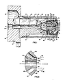
- a body 10 in the atomizer of Figures 1 and 2, includes a flange portion 12 and has an input end 14 and a discharge end 16.
- the body 10 further includes an internal bore 18 that is longitudinally aligned on the axis A-A'.
- the internal bore 18 opens to a slurry inlet 20 at one end and a plurality of separate passageways 22 at the opposite end.
- the body 10 also includes an input port 28 and a passageway 30 that forms an opening in a side 32 of the body 10.
- a casing 34 is threadingly engaged with the body 10 and covers at least the discharge end 16 of the body 10.
- the casing 34 includes a discharge end 36 and co-operates with the body 10 to define an annulus 38.
- a forming element 40 is located at the discharge end 16 of the body 10 and includes an input face 42 at one end and a projection 44 at the other end.
- the input face 42 contacts the discharge end 16 of the body 10 and the projection 44 generally extends in the direction of the longitudinal axis A-A' and away from the discharge end 16 of the body 10.
- the projection 44 includes a tubular member 45 located at the free end of the projection 44.
- the tubular member 45 includes a discharge end face 45a.
- the forming element 40 further includes a discharge face 46 that is oppositely disposed to the input face 42, and a plurality of passageways 48 extending between the input face 42 and the discharge face 46.
- the passageways 48 communicate with the passageways 22 in the body 10 and, preferably, are aligned therewith by a pin or other locating device.
- the forming element 40 further includes an internal bore 50 and a plurality of lateral passageways 52 that open to the internal bore 50 and are in fluid communication with the annulus 38.
- the passageways 52 are aligned tangentially to the internal bore 50 such that fluid flowing from the annulus 38 to the internal bore 50 is caused to swirl in a given sense inside the internal bore 50.
- the passageways 48 are aligned on an axis tangential to the internal bore 50 such that slurry flowing through the passageways 48 tends to rotate around the projection 44.
- a conical section 54 is located adjacent the discharge the face 46 of the forming element 40 and includes an inner conical surface 56, an outer conical surface 58, a base end 60, and an apical end 62.
- the base end 60 contacts the discharge face 46 of the forming element 40, the apical end 62 forms an orifice 64 that is concentric with respect to the internal bore 50 of the forming element 40 and the outer surface 58 forms a rim 68 at the orifice 64.
- the inner conical surface 56 co-operates with the projection 44 and the discharge face 46 of the forming element 40 to define a conical chamber 65 which communicates with the passageways 22 of the body 10 through the passageways 48 in the forming element 40.
- the orifice 64 co-operates with the tubular member 45 of the forming element 40 to define an annulus 66 therebetween.
- the rim 68 of the orifice 64 is in substantially the same plane as the discharge end face 45a of the tubular member 45, such plane being perpendicular to the longitudinal axis A-A'.
- a swirler 70 is located between the discharge end 36 of the casing 34 and the base end 60 of the conical section 54.
- the swirler 70 includes an annular ring 71a that is integrally connected to a cone-shaped portion 71b that defines a discharge orifice 71c.
- the annular ring 71a of the swirler 70 contacts the discharge end 36 of the casing 34 and the base end 60 of the conical section 54.
- the discharge end 36 of the casing 34 co-operates with the discharge end 16 of the base 10 to maintain the swirler 70, the conical section 54 and the forming element 40 in compression therebetween.
- the swirler 70 co-operates with the conical section 54 to define a swirl chamber 72 therebetween.
- the swirler 70 also provides a flow path between the annulus 38 and the swirl chamber 72.
- this flow path is a plurality of lateral bores 76 that are aligned tangentially with respect to the conical section 54 and the internal bore 50 such that swirled fluid is provided to the swirl chamber 72 from the annulus 38 through the lateral bores 76.
- the lateral bores 76 are tangentially aligned to the internal bore 50 in an opposite sense from the tangential alignment of the lateral passageways 52.
- the fluid provided to the internal bore 50 is swirled in an opposite sense from the fluid provided to the swirl chamber 72.
- the passageways 48 of the forming element 40 are tangentially aligned with respect to the internal bore 50 to provide swirled flow to the conical chamber 65.
- a fuel slurry such as a coal/water slurry
- compressed gas such as air or steam
- the fuel slurry flows through the central bore 18 to the passageways 22 and from the passageways 22 the slurry flows through the passageways 48 into the conical chamber 65.
- the compressed gas provided to the input port 28 passes through the passageway 30 into the annulus 38.
- the gas in the annulus 38 flows through the lateral passageway 52 and is swirled through the internal bore 50 in a general direction towards the discharge face 45a of the tubular member 45.
- the gas in the annulus 38 also passes through the lateral bores 76 into the swirl chamber 72 and is swirled towards the discharge orifice 71c.
- the swirling gas exiting the tubular member 45 and the swirling gas from the lateral bores 76 interact with the continuous cylindrical film of slurry flowing from the annulus 66. This interaction atomizes the slurry film and mixes it thoroughly with the gas. The atomized slurry then exits the nozzle through the discharge orifice 64.
- the swirling gas exiting the tubular member 45 in addition to atomizing and mixing the cylindrical slurry film, acts against the inside of the cylindrical slurry film such that it tends to maintain the film from collapsing and tends to retard the formation of slugs in the sheet.
- the angular momentum of the cylindrical film that results from the swirl of the slurry in the conical chamber 65 may be very low. Consequently, for these applications, the gas exiting the tubular member 45 can be swirled in the opposite sense from the gas in the swirl chamber 72 more fully to atomize the slurry film and thoroughly mix the particles with the gas.
- the radial dimension of the annulus 66 is selected with regard to the maximum particle size for the slurry, the preferred slurry velocity through the annulus 66 and the flow rate required for the nozzle. It is preferable to limit the slurry velocity at the annulus 66 in order to control erosion of the annular surfaces by the slurry particles. Thus, the preferred embodiment avoids exposure of the nozzle's internal surfaces to high velocity slurry particles.
- the preferred size of annulus 66 is 1.02 mm (0.040 inch) width and 6.35 mm (0.250 inch) outer diameter.
- the position of the discharge face 45a of the tubular member 45 in the same plane as the rim 68 of the conical section 54 is preferred because this arrangement has been found to provide greater atomization and mixing of the cylindrical slurry film.
Landscapes
- Engineering & Computer Science (AREA)
- Chemical & Material Sciences (AREA)
- Combustion & Propulsion (AREA)
- Mechanical Engineering (AREA)
- General Engineering & Computer Science (AREA)
- Nozzles (AREA)
Applications Claiming Priority (2)
| Application Number | Priority Date | Filing Date | Title |
|---|---|---|---|
| US673294 | 1984-11-20 | ||
| US06/673,294 US4616784A (en) | 1984-11-20 | 1984-11-20 | Slurry atomizer |
Publications (2)
| Publication Number | Publication Date |
|---|---|
| EP0182545A2 true EP0182545A2 (de) | 1986-05-28 |
| EP0182545A3 EP0182545A3 (de) | 1988-03-23 |
Family
ID=24702066
Family Applications (1)
| Application Number | Title | Priority Date | Filing Date |
|---|---|---|---|
| EP85308069A Withdrawn EP0182545A3 (de) | 1984-11-20 | 1985-11-06 | Schlammzerstäuber |
Country Status (4)
| Country | Link |
|---|---|
| US (1) | US4616784A (de) |
| EP (1) | EP0182545A3 (de) |
| JP (1) | JPS61130722A (de) |
| CA (1) | CA1246640A (de) |
Cited By (4)
| Publication number | Priority date | Publication date | Assignee | Title |
|---|---|---|---|---|
| WO1993006417A1 (en) * | 1991-09-27 | 1993-04-01 | Abb Carbon Ab | Method and nozzle for supplying paste fuel to a fluidized bed |
| US5227017A (en) * | 1988-01-29 | 1993-07-13 | Ohkawara Kakohki Co., Ltd. | Spray drying apparatus equipped with a spray nozzle unit |
| DE4212360A1 (de) * | 1992-04-13 | 1993-10-14 | Babcock Energie Umwelt | Brennerlanze zum Zerstäuben einer Kohle-Wasser-Suspension |
| US5499768A (en) * | 1989-05-31 | 1996-03-19 | Ohkawara Kakohki Co., Ltd. | Spray nozzle unit |
Families Citing this family (16)
| Publication number | Priority date | Publication date | Assignee | Title |
|---|---|---|---|---|
| JPS61173016A (ja) * | 1985-01-25 | 1986-08-04 | ドウマツク・オツフエネ・ハンデルスゲゼルシヤフト・ドクトル・テヒニツシエ・ルードヴイツヒ・カルーツア・ウント・コンパニー | 流動可燃性媒体の霧化ノズル |
| FR2598349B1 (fr) * | 1986-05-07 | 1988-09-23 | Gilles Pierre | Procede de fabrication de murs en pises, ou terre stabilisee, machine a projeter adaptee a sa mise en oeuvre, et mur ainsi obtenu |
| US4773596A (en) * | 1987-04-06 | 1988-09-27 | United Technologies Corporation | Airblast fuel injector |
| US4786682A (en) * | 1987-06-25 | 1988-11-22 | Ppg Industries, Inc. | Coating compositions prepared from Michael adducts |
| US4941617A (en) * | 1988-12-14 | 1990-07-17 | United Technologies Corporation | Airblast fuel nozzle |
| US5135169A (en) * | 1991-01-16 | 1992-08-04 | Mensink Daniel L | Self-cleaning feed distributing delivery device for glass melters |
| US5697553A (en) * | 1995-03-03 | 1997-12-16 | Parker-Hannifin Corporation | Streaked spray nozzle for enhanced air/fuel mixing |
| FR2827198B1 (fr) * | 2001-07-10 | 2004-04-30 | Air Liquide | Dispositif de pulverisation et procede de mise en oeuvre |
| US6920749B2 (en) * | 2002-03-15 | 2005-07-26 | Parker-Hannifin Corporation | Multi-function simplex/prefilmer nozzle |
| GB0426429D0 (en) * | 2004-12-01 | 2005-01-05 | Incro Ltd | Nozzle arrangement and dispenser incorporating nozzle arrangement |
| US20070075158A1 (en) * | 2005-09-22 | 2007-04-05 | Pelletier Robert R | Nozzle assembly |
| US8057220B2 (en) * | 2008-02-01 | 2011-11-15 | Delavan Inc | Air assisted simplex fuel nozzle |
| US20170335441A1 (en) * | 2009-03-23 | 2017-11-23 | Monitor Coatings Limited | Nozzle for thermal spray gun and method of thermal spraying |
| FR2984857B1 (fr) * | 2011-12-23 | 2015-02-13 | Rexam Dispensing Sys | Bouton poussoir pour un systeme de distribution d'un produit sous pression |
| CN113262894B (zh) * | 2021-04-19 | 2025-05-27 | 上海顺晟实业有限公司 | 喷涂浆料用的喷嘴结构及具有该结构的喷涂设备 |
| EP4309799A1 (de) * | 2022-07-22 | 2024-01-24 | Blue Planet Aqua UG | Vorrichtung zur verwirbelung einer flüssigkeit |
Family Cites Families (9)
| Publication number | Priority date | Publication date | Assignee | Title |
|---|---|---|---|---|
| US1451063A (en) * | 1923-04-10 | Burner | ||
| US1396086A (en) * | 1918-07-20 | 1921-11-08 | Alfred R Anthony | Fuel-oil burner |
| US1342732A (en) * | 1918-12-30 | 1920-06-08 | Alfred R Anthony | Fuel-oil burner |
| US1567482A (en) * | 1919-12-10 | 1925-12-29 | Alfred R Anthony | Fuel burner |
| US3310240A (en) * | 1965-01-07 | 1967-03-21 | Gen Motors Corp | Air atomizing nozzle |
| US3684186A (en) * | 1970-06-26 | 1972-08-15 | Ex Cell O Corp | Aerating fuel nozzle |
| US3685741A (en) * | 1970-07-16 | 1972-08-22 | Parker Hannifin Corp | Fuel injection nozzle |
| FR2206796A5 (de) * | 1972-11-13 | 1974-06-07 | Snecma | |
| US3980233A (en) * | 1974-10-07 | 1976-09-14 | Parker-Hannifin Corporation | Air-atomizing fuel nozzle |
-
1984
- 1984-11-20 US US06/673,294 patent/US4616784A/en not_active Expired - Fee Related
-
1985
- 1985-10-28 CA CA000494023A patent/CA1246640A/en not_active Expired
- 1985-11-06 EP EP85308069A patent/EP0182545A3/de not_active Withdrawn
- 1985-11-20 JP JP60260955A patent/JPS61130722A/ja active Pending
Cited By (6)
| Publication number | Priority date | Publication date | Assignee | Title |
|---|---|---|---|---|
| US5227017A (en) * | 1988-01-29 | 1993-07-13 | Ohkawara Kakohki Co., Ltd. | Spray drying apparatus equipped with a spray nozzle unit |
| US5499768A (en) * | 1989-05-31 | 1996-03-19 | Ohkawara Kakohki Co., Ltd. | Spray nozzle unit |
| WO1993006417A1 (en) * | 1991-09-27 | 1993-04-01 | Abb Carbon Ab | Method and nozzle for supplying paste fuel to a fluidized bed |
| US5511725A (en) * | 1991-09-27 | 1996-04-30 | Abb Carbon Ab | Method and nozzle for supplying paste fuel to a fluidized bed |
| DE4212360A1 (de) * | 1992-04-13 | 1993-10-14 | Babcock Energie Umwelt | Brennerlanze zum Zerstäuben einer Kohle-Wasser-Suspension |
| EP0565814A3 (en) * | 1992-04-13 | 1993-11-24 | Babcock Energie Umwelt | Burner torch for pulverising a coal-water suspension |
Also Published As
| Publication number | Publication date |
|---|---|
| US4616784A (en) | 1986-10-14 |
| JPS61130722A (ja) | 1986-06-18 |
| CA1246640A (en) | 1988-12-13 |
| EP0182545A3 (de) | 1988-03-23 |
Similar Documents
| Publication | Publication Date | Title |
|---|---|---|
| US4616784A (en) | Slurry atomizer | |
| US4819878A (en) | Dual fluid atomizer | |
| EP0349540B1 (de) | Zerstäuber | |
| US5484107A (en) | Three-fluid atomizer | |
| EP0140477B1 (de) | Luftdralldüse | |
| US4255125A (en) | Mixing apparatus and the uses thereof | |
| US5188296A (en) | Pulp dispersion lance | |
| US4773597A (en) | Nozzle for spraying liquids | |
| US4195779A (en) | Mixing apparatus with outlet nozzle and uses thereof | |
| US3116017A (en) | Fuel nozzle | |
| US3883076A (en) | Rotary nozzle for spraying low-caloric fluid viscous substances in process of burning | |
| US2539314A (en) | Nozzle | |
| US5516046A (en) | Extended wear life low pressure drop right angle multi-exit orifice dual-fluid atomizer with replaceable wear materials | |
| US1428896A (en) | Steam-atomizing fuel-oil burner | |
| US5363782A (en) | Apparatus and process for combusting fluid fuel containing solid particles | |
| EP0128805A2 (de) | Doppelzerstäuber für Flüssigkeiten | |
| US1750602A (en) | Device for vaporizing liquids | |
| JPS59170611A (ja) | スラリ−状の燃料の噴霧方法と装置 | |
| US5511728A (en) | Dual fluid atomizer for high solids soil paste containing pebbles or agglomerates | |
| RU2039909C1 (ru) | Способ распыла жидкостей | |
| GB2085758A (en) | Atomisation of liquids | |
| JPS63226513A (ja) | アトマイザ | |
| JPS5987061A (ja) | 内部混合式霧化器 | |
| JPS58198612A (ja) | 燃料噴霧アトマイザ | |
| US3244375A (en) | Dual fluid compressor and sprayer |
Legal Events
| Date | Code | Title | Description |
|---|---|---|---|
| PUAI | Public reference made under article 153(3) epc to a published international application that has entered the european phase |
Free format text: ORIGINAL CODE: 0009012 |
|
| AK | Designated contracting states |
Kind code of ref document: A2 Designated state(s): DE FR GB IT NL SE |
|
| PUAL | Search report despatched |
Free format text: ORIGINAL CODE: 0009013 |
|
| AK | Designated contracting states |
Kind code of ref document: A3 Designated state(s): DE FR GB IT NL SE |
|
| 17P | Request for examination filed |
Effective date: 19880902 |
|
| 17Q | First examination report despatched |
Effective date: 19890202 |
|
| STAA | Information on the status of an ep patent application or granted ep patent |
Free format text: STATUS: THE APPLICATION IS DEEMED TO BE WITHDRAWN |
|
| 18D | Application deemed to be withdrawn |
Effective date: 19890815 |
|
| RIN1 | Information on inventor provided before grant (corrected) |
Inventor name: SIMMONS, HAROLD C. Inventor name: HARDING, CURTIS F. |