EP0182637A2 - Tubes à rayons X - Google Patents
Tubes à rayons X Download PDFInfo
- Publication number
- EP0182637A2 EP0182637A2 EP85308364A EP85308364A EP0182637A2 EP 0182637 A2 EP0182637 A2 EP 0182637A2 EP 85308364 A EP85308364 A EP 85308364A EP 85308364 A EP85308364 A EP 85308364A EP 0182637 A2 EP0182637 A2 EP 0182637A2
- Authority
- EP
- European Patent Office
- Prior art keywords
- anode
- filaments
- ray tube
- region
- cathode
- Prior art date
- Legal status (The legal status is an assumption and is not a legal conclusion. Google has not performed a legal analysis and makes no representation as to the accuracy of the status listed.)
- Withdrawn
Links
Images

Classifications
-
- H—ELECTRICITY
- H01—ELECTRIC ELEMENTS
- H01J—ELECTRIC DISCHARGE TUBES OR DISCHARGE LAMPS
- H01J35/00—X-ray tubes
- H01J35/24—Tubes wherein the point of impact of the cathode ray on the anode or anticathode is movable relative to the surface thereof
-
- H—ELECTRICITY
- H01—ELECTRIC ELEMENTS
- H01J—ELECTRIC DISCHARGE TUBES OR DISCHARGE LAMPS
- H01J35/00—X-ray tubes
- H01J35/02—Details
- H01J35/04—Electrodes ; Mutual position thereof; Constructional adaptations therefor
- H01J35/06—Cathodes
- H01J35/064—Details of the emitter, e.g. material or structure
-
- H—ELECTRICITY
- H05—ELECTRIC TECHNIQUES NOT OTHERWISE PROVIDED FOR
- H05G—X-RAY TECHNIQUE
- H05G1/00—X-ray apparatus involving X-ray tubes; Circuits therefor
- H05G1/08—Electrical details
- H05G1/26—Measuring, controlling or protecting
- H05G1/30—Controlling
- H05G1/52—Target size or shape; Direction of electron beam, e.g. in tubes with one anode and more than one cathode
-
- H—ELECTRICITY
- H01—ELECTRIC ELEMENTS
- H01J—ELECTRIC DISCHARGE TUBES OR DISCHARGE LAMPS
- H01J2235/00—X-ray tubes
- H01J2235/06—Cathode assembly
- H01J2235/068—Multi-cathode assembly
Definitions
- the present invention relates to x-ray tubes.
- electrons produced by a filament are directed on to an anode at a focal spot to produce x-rays.
- x-ray tubes can generate multiple focal spots of different sizes for different diagnostic applications.
- One size spot is required for general purposes, a different size spot for arthograms, and an additional size spot for digital radiography.
- a typical procedure for generating multiple size focal spots is to energize a different length filament for each of the focal spots.
- a second problem results when longer filaments are used.
- a very popular method of cooling x-ray tube anodes is to rotate them so that electrons strike a band about their surface rather than a single spot.
- the focal spot extends across this band with one end of the spot located at an inner region on the anode and an opposite end of the focal spot on an outer region.
- the anode surface at the outer region is moving faster than the inner region, yet with a single filament the electron -flux is the same for both inner and outer focal spot portions. This results in an undesirable energy distribution along the x-ray focal spot.
- an x-ray tube comprising: an anode and a cathode including at least two filaments arranged to direct electrons at said anode so as to produce x-rays where the electrons strike the anode characterised in that the filaments are arranged so as respectively to produce x-rays substantially in respective contiguous portions of a single unitary region.
- the two or more filaments may be made less prone to failure than an equivalent single filament.
- the electron flux produced in said region is suitably arranged to increase with distance from said axis of rotation, for example, by differences in the energising currents of the filaments.
- Figure 1 shows an x-ray tube 10 having a rotating anode 12 and stationary cathode 14.
- the anode and cathode are supported inside an evacuated chamber 16 having a transmissive window 18 through which x-radiation generated by electron impingement upon the anode can be transmitted for use in a diagnostic and/or clinical situation.
- the anode 12 is supported in a bearing 20 for rotation about a centre axis 22 passing approximately through the centre of the evacuated chamber 16. Electrons impinging upon the anode 12 thus strike its surface along a ring rather than a single spot. In this way, excessive heat buildup on the anode is avoided.
- the anode 12 and cathode 14 are separated by a large electrical potential which causes electrons to accelerate from the stationary cathode to the rotating anode.
- a single high voltage cable 24 is routed from the exterior of the chamber 16 and electrically coupled to the rotating anode 12. This cable 24 carries a positive voltage of approximately 75,000 volts.
- a high voltage input 26 to the cathode carries a high negative voltage of approximately the same magnitude as the positive voltage routed through the cable 24. In combination, these two inputs separate the cathode and the anode by 150,000 volts.
- FIGS 2 and 3 illustrate in more detail the structure of the cathode 14.
- the cathode 14 includes a cathode cup 28 to which are mounted two cathode filaments 30, 32.
- the cathode cup 28 defines two elongated grooves 34 extending across the width of the cathode in which these two filaments are mounted.
- the energized cathode cup 28 creates an electric field in the vicinity of these grooves to focus and shape the electrons which are thermionically emitted from the two filaments 30, 32.
- the two filaments are mounted in an overlapping or staggered relationship.
- This orientation in combination with the focusing effect of the electric field from the cathode cup causes electrons from the two filaments to strike the anode at different locations and in particular at respective contiguous portions of a single unitary region so that a single anode apot is formed.
- a single unitary elongated spot region 40 is seen to be made up of two spot portions 40a and 40b, wherein one of the portions 40a is generated by electrons thermionically emitted from the first filament 30 and the second portion 40b is generated by electrons from the second filament 32.
- the spot portion 40a corresponding to the filament 30 is closer to the anode axis of rotation 22 than the spot portion 40b corresponding to the filament 32.
- electrons from the filament 30 strike a part of the surface of the anode 12 which is moving slower than the part which electrons from the filament 32 strike.
- the two filaments 30, 32 are energized by different currents and therefore produce different electron fluxes at the anode.
- the filament 32 which generates the electrons for the outermost spot portion 40b produces a greater electron flux than the filament 30 generating the electrons for the innermost spot portion 40a.
- the appropriate electron power density P for a given spot portion depends upon the distance R of that focal spot portion from the centre of the anode.
- the current for the filament for each spot portion is determined in accordance with a relationship so that the electron power density P impinging on the anode is equal to a constant K times the square root of the distance:
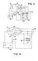
- FIGS 5 and 6 show alternate embodiments of circuitry for energizing the two filaments 30, 32 in this controlled manner.
- each filament 30, 32 is connected to its own filament transformer 42, 44.
- a high voltage source 50 provides a voltage between the anode and cathode.
- Two alternating current sources 52, 54 are each coupled to a respective one of the transformers 42, 44.
- a high voltage pulse 60 energizes the cathode cup 28 in a selected mode to provide the required pulse current of the x-ray tube.
- a single transformer 56 is required for energizing the two filaments 30, 32.
- a resistor 58 in series with filament 30 causes the current passing through the filament 30 to be less than the current through the filament 32.
- the Figure 6 embodiment generates a single size focal spot from the x-ray tube whereas the Figure 5 embodiment through selective energization of both or one or the other of the two filaments can provide multiple size focal spots.
- a focal spot 40a from that filament is produced on the anode.
- filament 32 is energized, focal spot 40b will be produced. If both are simultaneously energized, the combined spot 40 is produced.
Landscapes
- Health & Medical Sciences (AREA)
- General Health & Medical Sciences (AREA)
- Toxicology (AREA)
- X-Ray Techniques (AREA)
Applications Claiming Priority (2)
| Application Number | Priority Date | Filing Date | Title |
|---|---|---|---|
| US67365784A | 1984-11-21 | 1984-11-21 | |
| US673657 | 1984-11-21 |
Publications (2)
| Publication Number | Publication Date |
|---|---|
| EP0182637A2 true EP0182637A2 (fr) | 1986-05-28 |
| EP0182637A3 EP0182637A3 (fr) | 1987-06-03 |
Family
ID=24703566
Family Applications (1)
| Application Number | Title | Priority Date | Filing Date |
|---|---|---|---|
| EP85308364A Withdrawn EP0182637A3 (fr) | 1984-11-21 | 1985-11-18 | Tubes à rayons X |
Country Status (2)
| Country | Link |
|---|---|
| EP (1) | EP0182637A3 (fr) |
| JP (1) | JPS61179045A (fr) |
Cited By (1)
| Publication number | Priority date | Publication date | Assignee | Title |
|---|---|---|---|---|
| EP0493249A1 (fr) * | 1990-12-28 | 1992-07-01 | General Electric Cgr S.A. | Procédé, tube et système pour éliminer une grille anti-diffusante fixe dans une image radiologique |
Families Citing this family (1)
| Publication number | Priority date | Publication date | Assignee | Title |
|---|---|---|---|---|
| JP2004265606A (ja) | 2003-01-21 | 2004-09-24 | Toshiba Corp | X線管装置 |
Family Cites Families (7)
| Publication number | Priority date | Publication date | Assignee | Title |
|---|---|---|---|---|
| US3452203A (en) * | 1965-08-31 | 1969-06-24 | Tokyo Shibaura Electric Co | Triode type x-ray tubes and method and apparatus for irradiating x-rays |
| US3591821A (en) * | 1967-04-19 | 1971-07-06 | Tokyo Shibaura Electric Co | Rotary anode type x-ray generator having emitting elements which are variably spaced from the central axis of cathode |
| US3649861A (en) * | 1970-09-09 | 1972-03-14 | Picker Corp | Double focus x-ray tube |
| US4065689A (en) * | 1974-11-29 | 1977-12-27 | Picker Corporation | Dual filament X-ray tube |
| US3946261A (en) * | 1975-01-03 | 1976-03-23 | The Machlett Laboratories, Inc. | Dual filament X-Ray tube |
| DE2850583A1 (de) * | 1978-11-22 | 1980-06-04 | Philips Patentverwaltung | Roentgenroehre mit zwei parallel nebeneinander angeordneten heizfaeden |
| US4315154A (en) * | 1979-11-08 | 1982-02-09 | Siemens Corporation | Multiple focus X-ray generator |
-
1985
- 1985-11-18 EP EP85308364A patent/EP0182637A3/fr not_active Withdrawn
- 1985-11-20 JP JP60260982A patent/JPS61179045A/ja active Pending
Cited By (3)
| Publication number | Priority date | Publication date | Assignee | Title |
|---|---|---|---|---|
| EP0493249A1 (fr) * | 1990-12-28 | 1992-07-01 | General Electric Cgr S.A. | Procédé, tube et système pour éliminer une grille anti-diffusante fixe dans une image radiologique |
| FR2671229A1 (fr) * | 1990-12-28 | 1992-07-03 | Gen Electric Cgr | Procede, tube et systeme pour eliminer une grille anti-diffusante fixe dans une image radiologique. |
| US5195120A (en) * | 1990-12-28 | 1993-03-16 | General Electric Cgr S.A. | Method, tube and system for eliminating a fixed antiscatter grid in a radiological image |
Also Published As
| Publication number | Publication date |
|---|---|
| EP0182637A3 (fr) | 1987-06-03 |
| JPS61179045A (ja) | 1986-08-11 |
Similar Documents
| Publication | Publication Date | Title |
|---|---|---|
| US5812632A (en) | X-ray tube with variable focus | |
| US1215116A (en) | X-ray apparatus. | |
| US7012989B2 (en) | Multiple grooved x-ray generator | |
| US4685118A (en) | X-ray tube electron beam switching and biasing method and apparatus | |
| US6181771B1 (en) | X-ray source with selectable focal spot size | |
| US3916202A (en) | Lens-grid system for electron tubes | |
| EP0147009B1 (fr) | Dispositif de balayage à rayons X | |
| EP1166317B1 (fr) | Procede et appareil servant a prolonger la duree de vie d'une cible anticathode | |
| US5576549A (en) | Electron generating assembly for an x-ray tube having a cathode and having an electrode system for accelerating the electrons emanating from the cathode | |
| US3882339A (en) | Gridded X-ray tube gun | |
| US4631742A (en) | Electronic control of rotating anode microfocus x-ray tubes for anode life extension | |
| US5511105A (en) | X-ray tube with multiple differently sized focal spots and method for operating same | |
| US6252935B1 (en) | X-ray radiator with control of the position of the electron beam focal spot on the anode | |
| US4689809A (en) | X-ray tube having an adjustable focal spot | |
| US4065689A (en) | Dual filament X-ray tube | |
| US3751701A (en) | Convergent flow hollow beam x-ray gun with high average power | |
| US4823371A (en) | X-ray tube system | |
| RU2540327C2 (ru) | Рентгеновский анод | |
| US4336476A (en) | Grooved X-ray generator | |
| GB2183904A (en) | Cathode focusing arrangement | |
| SE424243B (sv) | Rontgenror for rontgendiagnostisk apparatur | |
| US4315154A (en) | Multiple focus X-ray generator | |
| US6556656B2 (en) | X-ray tube provided with a flat cathode | |
| US4017757A (en) | Multi-target X-ray tube | |
| US4359660A (en) | Series diode X-ray source |
Legal Events
| Date | Code | Title | Description |
|---|---|---|---|
| PUAI | Public reference made under article 153(3) epc to a published international application that has entered the european phase |
Free format text: ORIGINAL CODE: 0009012 |
|
| AK | Designated contracting states |
Kind code of ref document: A2 Designated state(s): DE FR GB NL |
|
| PUAL | Search report despatched |
Free format text: ORIGINAL CODE: 0009013 |
|
| AK | Designated contracting states |
Kind code of ref document: A3 Designated state(s): DE FR GB NL |
|
| 17P | Request for examination filed |
Effective date: 19871022 |
|
| 17Q | First examination report despatched |
Effective date: 19880928 |
|
| STAA | Information on the status of an ep patent application or granted ep patent |
Free format text: STATUS: THE APPLICATION IS DEEMED TO BE WITHDRAWN |
|
| 18D | Application deemed to be withdrawn |
Effective date: 19890209 |
|
| RIN1 | Information on inventor provided before grant (corrected) |
Inventor name: PLEIL, VIKTOR W. Inventor name: FURBEE, AVERY D. |