EP0182733B1 - Kapselung für magnetischen Schalter - Google Patents
Kapselung für magnetischen Schalter Download PDFInfo
- Publication number
- EP0182733B1 EP0182733B1 EP85630189A EP85630189A EP0182733B1 EP 0182733 B1 EP0182733 B1 EP 0182733B1 EP 85630189 A EP85630189 A EP 85630189A EP 85630189 A EP85630189 A EP 85630189A EP 0182733 B1 EP0182733 B1 EP 0182733B1
- Authority
- EP
- European Patent Office
- Prior art keywords
- assembly according
- housing
- shaft
- cavity
- bore
- Prior art date
- Legal status (The legal status is an assumption and is not a legal conclusion. Google has not performed a legal analysis and makes no representation as to the accuracy of the status listed.)
- Expired - Lifetime
Links
- 239000002775 capsule Substances 0.000 claims description 64
- 235000014676 Phragmites communis Nutrition 0.000 claims description 21
- 239000004020 conductor Substances 0.000 claims description 15
- 239000000463 material Substances 0.000 claims description 13
- 230000000007 visual effect Effects 0.000 claims description 13
- 239000000356 contaminant Substances 0.000 claims description 6
- 230000004907 flux Effects 0.000 claims description 5
- 238000003780 insertion Methods 0.000 claims description 5
- 230000037431 insertion Effects 0.000 claims description 5
- 230000001419 dependent effect Effects 0.000 claims description 3
- 238000004880 explosion Methods 0.000 claims description 3
- 239000007787 solid Substances 0.000 claims description 3
- XAGFODPZIPBFFR-UHFFFAOYSA-N aluminium Chemical compound [Al] XAGFODPZIPBFFR-UHFFFAOYSA-N 0.000 claims description 2
- 229910052782 aluminium Inorganic materials 0.000 claims description 2
- 229910001220 stainless steel Inorganic materials 0.000 claims description 2
- 239000010935 stainless steel Substances 0.000 claims description 2
- 230000000295 complement effect Effects 0.000 claims 1
- 238000000034 method Methods 0.000 description 7
- 239000004593 Epoxy Substances 0.000 description 5
- 239000007789 gas Substances 0.000 description 4
- 230000001960 triggered effect Effects 0.000 description 4
- 239000011521 glass Substances 0.000 description 3
- XUIMIQQOPSSXEZ-UHFFFAOYSA-N Silicon Chemical compound [Si] XUIMIQQOPSSXEZ-UHFFFAOYSA-N 0.000 description 2
- 238000005538 encapsulation Methods 0.000 description 2
- 239000012530 fluid Substances 0.000 description 2
- 229910052710 silicon Inorganic materials 0.000 description 2
- 239000010703 silicon Substances 0.000 description 2
- 240000008042 Zea mays Species 0.000 description 1
- 235000005824 Zea mays ssp. parviglumis Nutrition 0.000 description 1
- 235000002017 Zea mays subsp mays Nutrition 0.000 description 1
- 230000002411 adverse Effects 0.000 description 1
- 238000005266 casting Methods 0.000 description 1
- 238000001816 cooling Methods 0.000 description 1
- 235000005822 corn Nutrition 0.000 description 1
- 230000007797 corrosion Effects 0.000 description 1
- 238000005260 corrosion Methods 0.000 description 1
- 230000007613 environmental effect Effects 0.000 description 1
- 239000002360 explosive Substances 0.000 description 1
- 238000002955 isolation Methods 0.000 description 1
- 239000000696 magnetic material Substances 0.000 description 1
- 238000012423 maintenance Methods 0.000 description 1
- 230000007257 malfunction Effects 0.000 description 1
- 238000000465 moulding Methods 0.000 description 1
- 230000001681 protective effect Effects 0.000 description 1
- 230000003068 static effect Effects 0.000 description 1
- 239000006188 syrup Substances 0.000 description 1
- 235000020357 syrup Nutrition 0.000 description 1
Images


Classifications
-
- F—MECHANICAL ENGINEERING; LIGHTING; HEATING; WEAPONS; BLASTING
- F16—ENGINEERING ELEMENTS AND UNITS; GENERAL MEASURES FOR PRODUCING AND MAINTAINING EFFECTIVE FUNCTIONING OF MACHINES OR INSTALLATIONS; THERMAL INSULATION IN GENERAL
- F16K—VALVES; TAPS; COCKS; ACTUATING-FLOATS; DEVICES FOR VENTING OR AERATING
- F16K37/00—Special means in or on valves or other cut-off apparatus for indicating or recording operation thereof, or for enabling an alarm to be given
- F16K37/0025—Electrical or magnetic means
- F16K37/0041—Electrical or magnetic means for measuring valve parameters
Definitions
- the invention relates generally to magnetic switches and more particularly to a housing assembly for environmentally isolating and securely mounting one or more magnetic switches in a predetermined fixed relationship to an actuating shaft.
- the invention will be specifically disclosed in connection with a housing for precisely mounting two limit switch modules positioned to magnetically detect the open and closed positions of a quarter turn actuating shaft.
- the closure member is moved by an actuating shaft which extends through an actuator housing.
- this extension of the actuating shaft out of the actuator housing is used to mechanically interconnect the closure member with a pair of rocker arms actuated limit switches.
- the actuating shaft moves the rocker arms at the end limits of closure member movement; and the movement of the rocker arms is used to open or close electrical contacts.
- the contacts in turn, open or close an electrical circuit to produce an output signal indicative of whether the closure member is in an open or closed position.
- Mechanical limit switches also poses limitations upon their use. Mechanical limit switches generally extend above valve actuators and have relatively high profiles. On occasion, such as when other process equipment or low ceiling dimensions must be taken into consideration, these high profiles restrict placement of the actuator.
- One of either the magnets or the reed switches is positioned to move with the closure member, with the other positioned on the valve body.
- An assembly having magnetic means for determining the angular position of a rotatable shaft, as recited in the precharacterizing portion of independent claim 1 is disclosed in FR-A-2 105 654.
- Two magnetically controlled elements or reed switches are embedded in the housing material during molding thereof. Electric conductors also embedded in the housing material are provided between the magnetically controlled elements and external connector pins.
- the object of the invention is to provide an assembly for determining the angular position of a rotatable shaft which permits replacement of the magnetically controlled element and facilitates quick and reliable positioning of the magnetically controlled element while insuring the isolation thereof against contaminants and protection against mechanical abuse in an industrial environment.
- the cavity is elongated and tangentially or transversely positioned with respect to the housing bore.
- Two cavities can be provided, orthogonally disposed with respect to both each other and to the bore, each having insertably disposed therein a potted capsule containing a magnetically controlled element.
- the housing assembly preferably includes multiple seals to protect the switching assembly from the ambient environment.
- the securing means includes at least one off-center locator pin extending from one axial end of each of the capsules.
- Each locator pin(s) is received by a corresponding locator cavity in the closed end of the cavities to prevent relative rotational movement between the capsule and the housing.
- one of the pins is preferably larger than the other with the corresponding locator cavities being matingly configured to avoid insertion of the locator pins into the improper locator cavities.
- the securing means can further include a self-locking external toothed ring in abutting relationship with each of the capsules to prevent relative axial movement between said capsules and said housing.
- the self-locking external toothed ring is in radially compressive relationship to the cavities.
- the cavities are preferably in different planes so as to avoid interference between the capsules and the conductors extending out of the capsules.
- the open ends of the cavities can be threaded, and a conduit fitting can be threadably received in at least one of said open ends to sealingly close the open end in watertight relationship to the housing.
- a plug is threadably inserted in the open end of the rotor cavity to sealingly close the opening in a watertight and/or explosion proof seal.
- Another optional feature involves the total encapsulation of a circuit board and a circuit controlled by the magnetically controlled element in the capsule.
- the magnetically controlled element includes a hermetically sealed reed switch.
- the circuit includes a pair of silicon controlled rectifiers responsive to the reed switch.
- a bore cap seal is preferably disposed at an axial end of the rotatable shaft.
- the bore cap seal can be sealingly interconnected to the housing to prevent entry of contaminants into the housing bore.
- a visual indicator disc may be fixed to the rotatable shaft to provide a visual indication of the angular position of the rotatable shaft through a window providing visual access to said visual indicator disc.
- the switch capsule is formed of a waterproof material.
- At least one magnet holder is provided for securing a permanent magnet about a circumferential sector of the rotatable shaft.
- the magnet holder is adjustably movable with respect to the shaft for varying the angular position of the permanent magnet on said shaft.
- the magnetic switch assembly has independently adjustable trip points for detecting the position of an actuating shaft.
- the magnetic switch assembly can provide an output signal compatible with computers and programmable controllers, and in another embodiment it may be used for producing a power output signal for medium AC power applications.
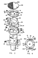
- Fig. 1 depicts a vane type actuator of the type commonly used for effectuating quarter turn rotational movement of a movable member, such as a valve closure member (not shown).
- the vane type actuator generally designated by the numeral 10, includes upper and lower housing portions 12 and 14 secured together by a plurality of screws 16.
- a movable vane or paddle (not shown) is disposed within the housing 12,14 and arranged to rotate in response to a pressure differential developed by the introduction of pressurized fluid into the housing 12,14 on one side of the vane.
- the vane is fixedly attached to an actuating shaft 18 which extends through both the upper and lower housing portions 12,14 and rotates with the vane.
- Fig. 1 further depicts a limit switch housing assembly, generally designated by the numeral 20, mounted on the top of the upper housing portion 12.
- the switch housing 20 has a centrally disposed bore into which the shaft 18 is received (the top portion of shaft 18 is obscured by the housing assembly 20 in Fig. 1, see Fig. 2).
- the housing assembly 20 includes a low profile housing 22 of generally rectangular configuration.
- the housing 22 is formed of nonmagnetic material, such as plastic, nonmagnetic stainless steel or, as in the preferred embodiment, an aluminum casting.
- the housing 22 is bolted to the upper housing portion 12 by a pair of bolts 24.
- a pair of epoxy potted switch capsules 26 and 28 are disposed within the housing 22. More specifically, the illustrated plastic switch capsules 26 and 28 are secured in closed ended drilled cavities 30 and 32 respectively formed in the housing 22, which cavities 30 and 32 have a configuration matching that of the respective switch capsules 26,28.
- the switch capsules are tangentially oriented with respect to the shaft 18.
- the switch capsules 26,28 are orthogonally oriented with respect to both each other and to the rotary axis of an adaptor shaft 18' interconnected to and rotatable with the shaft 18.
- the illustrated shaft adaptor 18' is securable to the shaft 18 through the agency of a set screw 19 (see Fig. 3).
- shaft as used in the present specification and claims will be used to denote either a shaft itself or any adaptor or extension thereof.
- the switch capsules 26 and 28 each contain electronic circuits, including magnetically controlled elements, such as reed switches (schematically depicted in Fig. 7), for detecting the angular position of magnets adjustably fixed to the shaft 18, as will be more fully discussed hereinafter. As may be realized from Fig. 2, all of the circuit components area either double or triple sealed.
- the housing 22 provides a first seal and isolates the entire switch modules 26 and 28 from dirt and process contaminants.
- the switch capsules 26,28 themselves include an epoxy covering 34. This covering 34 provides a second seal which encapsulates both the magnetic reed switches and circuit boards 35 containing associated electronic circuit elements. Insulated conductors 37 (see Figs.
- the reed switches are hermetically sealed in a glass enclosure 36.
- the reed switch contacts are triple sealed from dirt and corrosion by the glass 36, epoxy 34 and housing 22; and all other circuit components and connections are double sealed by the epoxy covering 34 and housing 22.
- the reed switches and associated elements are described in greater detail below in connection with Fig. 7.
- FIG. 3 the assembly depicted in Fig. 2 for adjustably holding magnets about the shaft 18 (or as specifically illustrated, a shaft adaptor 18') is illustrated in greater detail.
- a first magnet holder 40 having a centrally disposed shaft receiving aperture 42 is fitted about the upper section of the shaft 18 (or shaft adaptor 18'), which shaft section 18 extends through the upper housing portion 12.
- a shoulder 44 on the shaft 18 (specifically illustrated as the shaft adaptor 18') limits axial movement of the magnet holder 40 onto the shaft 18.
- the illustrated magnet holder 40 includes a bearing surface 41 on one axial side as well as a pair of cooperating magnet mounts 46A and 46B disposed on one circumferential sector. As described in connection with Fig.
- a magnet 45 is disposed between these magnet mounts 46A and 46B.
- the magnet 45 (as well as magnet 55 disposed between magnet mounts 50A and 50B of magnet holder 48, described hereinafter) is omitted from the drawings of Figs. 2 and 3.
- a second magnet holder 48 is fitted about the shaft 18 on top of the first magnet holder 40.
- This second illustrated magnet holder 48 is identical to the first illustrated magnet holder 40. However, in assembled positions, the second magnet bolder 48 is inverted with respect to the first magnet holder 40 so as to position the axial bearing surface (not shown) on this second magnet holder 48 into contact with the corresponding bearing surface 41 of magnet holder 40.
- Magnet holder 48 further includes a pair of cooperating magnet mounts 50A and 50B which are illustrated as being separated from magnet mounts 44 and 46 by approximately 180° in Fig. 3.
- An indicator clamping member 60 is fixedly secured to the shaft 18 above the second magnet holder 48.
- This indicator clamping member 60 includes a pair of downwardly depending bosses 62 and 64 extending from a base 66 having a ringlike configuration.
- the base 66 defines a central opening 68 which includes a pair of oppositely disposed flats 70 and 72.
- the ringlike base 66 is fitted about the top of shaft 18 (specifically illustrated as the shaft adaptor 18' in Fig. 3) with the flats 70 and 72 on indicator clamping member 60 engaging corresponding flats 76 and 78 on the sides of shaft 18 to prevent relative rotation between the indicator clamping member 60 and the shaft 18.
- the boss 62 has a threaded apertures 65 for receiving a set screw 63 for selectively fixing the indicator clamping member 60 to the shaft 18.
- threaded apertures 67 (see Fig. 4) in the magnet holders 40,48 receive set screws 88 for securing the magnet holders 40,48 at a selected angular position about shaft 18.
- magnet mounts 46A and 46B on magnet holder 40 are used to securely hold a permanent magnet 45.
- the magnet 45 is interposed between a pair of magnetic pole pieces 41 and 47 which serve to directionalize the magnetic flux generated by magnet 45.
- a pair of set screws 49 extend through mount 46B to engage the pole piece 47 and to compressingly hold the magnet 45 between the magnetic pole pieces 41 and 47.
- magnet mounts 50A and 50B are used to securely hold a permanent magnet 55 on magnet holder 48.
- a pair of set screws 51 are advanced through mount 50B to compressingly engage a magnetic pole piece 53 and to secure magnet 55 between pole piece 53 and a further pole piece 57.
- the magnet holders 40,48 radially separate the magnets 45,55 from the shaft 18 and permit the use of a shaft 18 formed of magnetic material without adversely effecting operation of the reed switches disposed in capsules 26,28.
- each of the switch capsules 26,28 has at least one off-center pin extending outwardly from one axial end of the switch capsules.
- each capsule 26,28 has a pair of locator pins 106,108.
- locator pin 106 is greater than the diameter of pin 108.
- the axial end of cavities 30 and 32 have correspondingly sized and shaped locator holes 110,112 for receiving these locator pins.
- locator pin 106 will not fit into hole 112. In this way, the cavities 30,32 insure proper location of the switch capsules 26,28 with respect to the shaft 18, and the receipt of locating pins 106,108 in locator holes 110,112 insures proper angular orientation.
- Switch capsules 26 and 28 are axially held in cavities 30,32 by self-locking external toothed rings 114 and 116 respectively.
- the rings 114,116 each have central openings for the passage of two insulated conductors 37 extending from each of the switch capsule 26,28. All of the conductors 37 exit housing 22 through a sealed fitting 118 (see Fig. 5) threadably received in the opening 102.
- opening 104 is also threaded and is blocked by a cap 120.
- Fig. 6 further shows that the cavity 30 is vertically offset (i.e., in a different plane) from cavity 32 in the preferred embodiment to allow insertion of the second inserted switch capsules 26,28 without interference from the conductors 37 extending from the first inserted capsule.
- the above described switch housing assembly is also explosion proof.
- the structural integrity of the housing 22 combined with the threaded openings 102,104 insure that any explosive gases within the cavities 30,32 would slowly escape about the threads of the openings 102,104 without exploding the housing 22.
- the relatively slow escape of gases about these threads provides cooling time for the heated gas and avoids the expulsion of the gases in a highly heated state.
- a visual indicator disc 122 is fixedly attachable to the top of the indicator clamping member 60 for rotation with the actuating shaft 18.
- the visual indicator disc 122 is divided into two visually distinct areas 122A and 122B.
- a bore cap seal cover 124 shown in Fig. 1 covers the visual indicator disc 122 and sealingly isolates the shaft 18 and magnet holding assembly from the ambient environment.
- the bore cap seal 124 preferably seals against an O-ring 125 circumferentially disposed in an annular groove 127 in the top of housing 22 (see Fig. 2).
- a further O-ring 129 is disposed in a groove 131 for sealingly interfacing the bottom portion of the housing 22.
- the bore cap seal 124 is shown with a plastic window 126 which visually reveals a portion of the indicator disc 122.
- the angular orientation of the seal cover 124 and disc 122 are coordinated so that one of the visually distinct areas 122A or 122B underlies the window 126 when the valve closure is in an open position and the other visually distinct area 122A or 122B underlies the window when the closure member is in the closed or shut position.
- the visually distinct areas 122A and 122B may include labels, as for example, the words "open” and "shut".
- the housing 22 further includes a pair of ports 109 and 111 which extend radially inwardly to the centrally disposed bore containing shaft 18. These ports 109,111 provide access to set screws 88, shown in Figs. 3 and 4, securing magnet holders 40,48 in selected angular position on the shaft 18. The set screw 88 may be loosened and retightened following angular adjustment of the magnet holder.
- the external openings of ports 109,111 are, of course, sealed during operation.
- removably threaded caps are used to seal these external openings of ports 109 and 111.
- Fig. 7 depicts a reed switch triggered switching circuit which is optionally disposed within each of the capsules for medium AC power applications. Such a circuit generates an output signal in response to the closure of a reed switch disposed within the glass enclosure 36 shown in Fig. 2.
- the specifically illustrated circuit 130 includes a pair of silicon-controlled rectifiers (SCR's) 132 and 134 connected between upper and lower rails 136 and 138 in an inverse-parallel configuration.
- SCR's silicon-controlled rectifiers
- the circuit 130 is activated by the closure of one of the hermetically sealed reed switches 140, which, as indicated in the description above, are closed by the influence of magnets 45,55 secured about the shaft 18.
- the load 152 will be connected across the voltage V between upper and lower rails 136 and 138 respectively during positive half cycles by SCR 134 and during negative half cycles by SCR 132. Therefore, full wave power is applied to the load 152 to simulate a normal switch closure.
- a varistor 154 is also shown across rails 136,138 to protect against transients exceeding the peak line voltage potential.
- the circuit 130 of Fig. 7 advantageously permits relatively high power AC switching with only a minimal volt-ampere switch load on the reed switch 140.
- Other solid state power switches for performing this same function will be apparent to those skilled in the art and may be used in accordance with the principles of the present invention.
- a single triac static switch circuit or a transistor switch could be employed.
- the magnetic reed switch is used directly without the remaining illustrated SCR components.
- the disclosed switch assembly facilitates quick and reliable insertion of a magnetic switch capsule in proper position and orientation with respect to a rotating shaft having a magnet disposed about one circumferential sector. Encapsulation of the magnetic switches and control circuits in watertight epoxy capsules and thereafter inserting these capsules into sealed cavities in the assembly housing provides multiple seals to isolate the switches, circuits and their connections against the many potentially harmful contaminants in an industrial environment.
- the magnets used to activate the magnetic switches are advantageously secured in adjustable magnet holders to vary the angular position of the shaft used to trip the magnetic switches.
- the switch capsules may also optionally encapsulate circuit components for generating a magnetic switch activated power output signal.
- the use of locator pins on the capsules with corresponding locator cavities insures quick and proper insertion of the capsules while preventing relative rotational movement between the capsules and the housing during operation.
- the use of a windowed bore cap seal eliminates entry of contaminants into the housing bore while still providing a visual indication of the shaft position.
- the switch capsules of the invention may be constructed to be readily removable for quick and inexpensive maintenance, if needed.
Landscapes
- Engineering & Computer Science (AREA)
- General Engineering & Computer Science (AREA)
- Mechanical Engineering (AREA)
- Switches That Are Operated By Magnetic Or Electric Fields (AREA)
- Transmission And Conversion Of Sensor Element Output (AREA)
- Measuring Volume Flow (AREA)
Claims (32)
- Vorrichtung zum Bestimmen der Winkelposition einer Welle (18), die ein magnetisches Element (45) hat, das um wenigstens einem Umfangssektor derselben zur gemeinsamen Drehung mit der Welle angeordnet ist; ein nichtmagnetisches Gehäuse (20), das aus starrem Material gebildet ist, wobei das Gehäuse (20) eine Bohrung hat, wobei die Welle (18) in der Bohrung angeordnet und in bezug auf diese drehbar ist; wenigstens einen Hohlraum (30), der sich in der Nähe der Bohrung in das Gehäusematerial erstreckt; ein magnetisch gesteuertes Element (140), das in dem Hohlraum (30) angeordnet ist, wobei das magnetisch gesteuerte Element (140) auf Magnetfluß anspricht, der durch das magnetische Element (45) erzeugt wird, und ein Ausgangssignal hat, das von der relativen Winkelposition zwischen der Welle (18) und dem Gehäuse (20) abhängig ist; und einen Leiter (37), der mit dem gesteuerten Element (140) verbunden ist und sich aus dem Hohlraum (30) hinaus erstreckt, um das Ausgangssignal des gesteuerten Elements (140) einer äußeren Stelle zu führen,
dadurch gekennzeichnet, daß das magnetisch gesteuerte Element (140) und die verbindung zwischen dem gesteuerten Element (140) und dem Leiter (37) in eine vergossene Kapsel (26) völlig eingekapselt sind, die in dem Hohlraum (30) lösbar angeordnet ist, und daß Einrichtungen vorgesehen sind zum wahlweisen Befestigen der Kapsel (26) in dem Hohlraum (30) in einer vorbestimmten Beziehung zu der Bohrung, um den Einfluß des durch das magnetische Element (45) erzeugten Magnetflusses auf das gesteuerte Element (140) zu maximieren. - Vorrichtung nach Anspruch 1, dadurch gekennzeichnet, daß sich die Längsabmessung des Hohlraums (30) in einer Richtung erstreckt, die im wesentlichen quer zu der Drehachse der Welle (18) ist.
- Vorrichtung nach Anspruch 1, dadurch gekennzeichnet, daß der wenigstens eine Hohlraum (30) in einer Richtung langgestreckt ist, die zu der Achse der Welle (18) im wesentlichen rechtwinkelig und in tangentialer Beziehung zu der Bohrung ist.
- Vorrichtung nach Anspruch 1, dadurch gekennzeichnet, daß die Kapsel (26, 28) aus Kunststoff besteht und in dem Hohlraum (26, 28) dauerhaft vergossen ist.
- Vorrichtung nach Anspruch 1, gekennzeichnet weiter durch einen zweiten Hohlraum (28), der sich in das Gehäuse (20) in einer Richtung erstreckt, die zu der Achse der Welle (18) im wesentlichen quer ist, eine zweite vergossene Kapsel (28), die in dem zweiten Hohlraum (32) einführbar angeordnet ist, wobei der zweite Hohlraum (32) im Winkelabstand am Umfang der Bohrung in bezug auf den wenigstens einen Hohlraum (30) und in der Nähe der Bohrung angeordnet ist, ein zweites magnetisch gesteuertes Element (140), das in der zweiten Kapsel (28) vollständig eingekapselt ist, wobei das zweite magnetisch gesteuerte Element (140) ein Ausgangssignal erzeugt, das von der Winkelposition der Welle (18) abhängig ist, und einen zweiten Leiter (37), der sich in die zweite Kapsel (28) in Kontakt mit dem zweiten magnetisch gesteuerten Element (140) erstreckt, um das Ausgangssignal des zweiten gesteuerten Elements einer äußeren Stelle zuzuführen, wobei die Verbindung zwischen dem zweiten gesteuerten Element (140) und dem zweiten Leiter (37) in der zweiten Kapsel (28) verkapselt ist.
- Vorrichtung nach Anspruch 5, dadurch gekennzeichnet, daß sowohl der wenigstens eine Hohlraum (30) als auch der zweite Hohlraum (32) langgestreckt und in bezug auf die Bohrung tangential angeordnet sind.
- Vorrichtung nach Anspruch 6, dadurch gekennzeichnet, daß der wenigstens eine Hohlraum (30) und der zweite Hohlraum (32) in bezug sowohl auf einander als auch auf die Bohrung orthogonal angeordnet sind.
- Vorrichtung nach Anspruch 6, dadurch gekennzeichnet, daß die Hohlräume (30, 32) jeweils eine insgesamt zylindrische Konfiguration haben und daß die Kapseln (26, 28) komplementäre Konfigurationen haben.
- Vorrichtung nach Anspruch 5, dadurch gekennzeichnet, daß die Hohlräume (30, 32) jeweils ein geschlossenes axiales Ende und ein offenes, aber verschließbares axiales Ende (102, 104) haben.
- Vorrichtung nach Anspruch 9, dadurch gekennzeichnet, daß die Befestigungseinrichtung wenigstens einen außermittigen Paßstift (106) aufweist, der sich von einem axialen Ende jeder Kapsel (26, 28) aus erstreckt, wobei der außermittige Paßstift (106) durch ein entsprechends Paßloch (110) in dem geschlossenen Ende der Hohlräume (30, 32) aufgenommen ist, um eine Relativdrehbewegung zwischen den Kapseln (26, 28) und dem Gehäuse (20) zu verhindern.
- Vorrichtung nach Anspruch 10, dadurch gekennzeichnet, daß die Befestigungseinrichtung zwei beabstandete Paßstifte (106, 108) und ein entsprechendes Paar Paßlöcher (110, 112) aufweist.
- Vorrichtung nach Anspruch 11, dadurch gekennzeichnet, daß einer der Paßstifte (106, 108) größer als der andere ist und daß die entsprechenden Paßlöcher (110, 112) passend ausgebildet sind, um das Einführen der Paßstifte (106, 108) in die ungeeigneten Paßlöcher (110, 112) zu vermeiden.
- Vorrichtung nach Anspruch 5, dadurch gekennzeichnet, daß die Befestigungseinrichtung weiter einen selbstarretierenden äußeren gezahnten Ring (114, 116) anstoßend an jede Kapsel (26, 28) aufweist, um eine relative Axialbewegung zwischen den Kapseln (26, 28) und dem Gehäuse (20) zu verhindern, wobei der Ring (114, 116) in radialer Druckbeziehung zu den Hohlräumen (30, 32) ist.
- Vorrichtung nach Anspruch 5, dadurch gekennzeichnet, daß die Hohräume (30, 32) in unterschiedlichen Ebenen nichtparallel zueinander sind, um eine Störung zwischen den Kapseln (26, 28) und den aus den Kapseln (26, 28) hinausführenden Leitern (37) zu vermeiden.
- Vorrichtung nach Anspruch 5, dadurch gekennzeichnet, daß sich die Hohlräume (30, 32) in der Nähe ihrer offenen Enden (102, 104) schneiden, damit die Leiter (37), die aus jeder Kapsel (26, 28) hinausführen, das Gehäuse (20) über eines (102) der offenen Enden (102, 104) verlassen können.
- Vorrichtung nach Anspruch 5, dadurch gekennzeichnet, daß die offenen Enden (102, 104) der Hohlräume (30, 32) mit Gewinde versehen sind und daß ein Leitungsanschlußstück (118) in wenigstens eines (102) der offenen Enden (102, 104) eingeschraubt ist, um das wenigstens eine offene Ende (102) an dem Gehäuse (20) in wasserdichter Beziehung dicht zu verschließen.
- Vorrichtung nach Anspruch 16, dadurch gekennzeichnet, daß ein Stopfen in das offene Ende (104) des anderen Hohlraums (32) eingeschraubt ist, um das offene Ende (104) des anderen Hohlraums (32) mit einer wasserdichten, explosionssicheren Dichtung dicht zu verschließen.
- Vorrichtung nach Anspruch 5, dadurch gekennzeichnet, daß das magnetisch gesteuerte Element hermetisch verschlossene Reed-Schalter (140) aufweist, die in Gehäuse (36) eingeschlossen sind, wobei die Kapseln (26, 28) die Gehäuse (36) der hermetisch verschlossenen Reed-Schalter (140) gänzlich einkapseln.
- Vorrichtung nach Anspruch 5, dadurch gekennzeichnet, daß wenigstens eine der Kapseln (26, 28) weiter eine Leiterplatte (35) und eine Schaltung (130), die durch das magnetisch gesteuerte Element gesteuert wird, gänzlich einkapselt.
- Vorrichtung nach Anspruch 19, dadurch gekennzeichnet, daß die Schaltung (130) einen Festkörperschaltkreis aufweist, der auf den Reed-Schalter (140) anspricht.
- Vorrichtung nach Anspruch 1, gekennzeichnet weiter durch einen Bohrungsdeckelverschluß (124), der an einem axialen Ende der Welle (18) angeordnet ist, wobei der Verschluß (124) mit dem Gehäuse (20) dicht verbunden ist, um das Eindringen von Verunreinigungen in die Gehäusebohrung zu verhindern.
- Vorrichtung nach Anspruch 21, weiter gekennzeichnet durch eine Sichtanzeigescheibe (122), die mit der Welle (18) bewegbar ist, um eine Sichtanzeige der Winkelposition der Welle (18) zu liefern, wobei der Bohrungsdeckelverschluß (124) ein Fenster (126) aufweist, der Sichtzugang zu der Sichtanzeigescheibe (122) gewährt.
- Vorrichtung nach Anspruch 5, dadurch gekennzeichnet, daß die Kapseln (26, 28) aus einem wassserundurchlässigen Material bestehen.
- Vorrichtung nach Anspruch 1, gekennzeichnet weiter durch wenigstens einen Magnethalter (40) zum Befestigen des magnetischen Elements (45) um einen Umfangssektor der Welle (18), wobei der Magnethalter (40) in bezug auf die Welle (18) einstellbar beweglich ist, um die Winkelposition des magnetischen Elements (45) an der Welle (18) zu verändern, und durch einen Permanentmagnet als magnetisches Element (45).
- Vorrichtung nach Anspruch 24, gekennzeichnet weiter durch wenigstens eine Öffnung (109), die sich durch das Gehäuse (20) hindurch zu der Bohrung erstreckt, um den wenigstens einen Magnethalter (40) zum Verändern der relativen Winkelpositionen zwischen dem wenigstens einen Magnethalter (40) und der Welle (18) zugänglich zu machen.
- Vorrichtung nach Anspruch 24 oder 25, gekennzeichnet weiter durch einen zweiten Magnethalter (48), wobei der zweite Magnethalter (48) dazu dient, wenigstens einen zweiten Permanentmagneten (55) um einen Umfangssektor der Welle (18) zu befestigen, wobei wenigstens einer der Magnethalter (40, 48) in bezug auf die Welle (18) einstellbar ist, um die Winkelposition wenigstens eines der Permanentmagnete (45, 55) in bezug auf die Welle (18) zu verändern.
- Vorrichtung nach Anspruch 26, gekennzeichnet weiter durch ein Paar Öffnungen (109, 111), die sich radial durch das Gehäuse (20) zu der Bohrung erstrecken, wobei diese Öffnungen (109, 110) die Magnethalter (40, 48) zum Einstellen der Winkelposition derselben in bezug auf die Welle (18) zugänglich machen.
- Vorrichtung nach Anspruch 1, dadurch gekennzeichnet, daß das Gehäuse (20) aus Aluminium besteht.
- Vorrichtung nach Anspruch 1, dadurch gekennzeichnet, daß das Gehäuse (20) aus Kunststoff besteht.
- Vorrichtung nach Anspruch 1, dadurch gekennzeichnet, daß die Kapseln (26, 28) aus einem Kunststoffmaterial bestehen.
- Vorrichtung nach Anspruch 5, dadurch gekennzeichnet, daß der erste und zweite Hohlraum (30, 32) in bezug sowohl auf einander als auch auf die Bohrung orthogonal ausgerichtet sind.
- Vorrichtung nach Anspruch 1, dadurch gekennzeichnet, daß das Gehäuse (20) aus nichtmagnetischem rostfreiem Stahl besteht.
Applications Claiming Priority (2)
| Application Number | Priority Date | Filing Date | Title |
|---|---|---|---|
| US06/673,885 US4663601A (en) | 1984-11-21 | 1984-11-21 | Magnetic switch housing assembly |
| US673885 | 1991-03-22 |
Publications (3)
| Publication Number | Publication Date |
|---|---|
| EP0182733A2 EP0182733A2 (de) | 1986-05-28 |
| EP0182733A3 EP0182733A3 (en) | 1990-03-28 |
| EP0182733B1 true EP0182733B1 (de) | 1992-07-22 |
Family
ID=24704487
Family Applications (1)
| Application Number | Title | Priority Date | Filing Date |
|---|---|---|---|
| EP85630189A Expired - Lifetime EP0182733B1 (de) | 1984-11-21 | 1985-11-12 | Kapselung für magnetischen Schalter |
Country Status (4)
| Country | Link |
|---|---|
| US (1) | US4663601A (de) |
| EP (1) | EP0182733B1 (de) |
| CA (1) | CA1234198A (de) |
| DE (1) | DE3586393T2 (de) |
Families Citing this family (35)
| Publication number | Priority date | Publication date | Assignee | Title |
|---|---|---|---|---|
| FI864811L (fi) * | 1985-12-11 | 1987-06-12 | Kontron Holding Ag | Centrifug. |
| US4904941A (en) * | 1987-12-23 | 1990-02-27 | Eaton Corporation | Gauge for detecting misalignment |
| US4891589A (en) * | 1987-12-23 | 1990-01-02 | Eaton Corporation | Displacement gauge that combines vector signals |
| US4939455A (en) * | 1988-09-02 | 1990-07-03 | Hamilton Standard Controls, Inc. | Sensor having two-wire connection to load |
| US5122741A (en) * | 1989-12-06 | 1992-06-16 | Alps Electric Co., Ltd. | Holding members for sensor and wiring members of magnetic rotary encoder |
| DE9000605U1 (de) * | 1990-01-20 | 1991-05-29 | UNIVAM Peter Janssen-Weets KG, 2878 Wildeshausen | Armatur |
| FR2660028B1 (fr) * | 1990-03-20 | 1994-12-09 | Roulements Soc Nouvelle | Roulement a capteur de position angulaire. |
| US5338283A (en) * | 1992-10-09 | 1994-08-16 | E. I. Du Pont De Nemours And Company | Centrifuge rotor identification system |
| US5424635A (en) * | 1992-11-18 | 1995-06-13 | Case Corporation | Shaft speed signal indicator |
| WO1996012133A1 (en) * | 1994-10-13 | 1996-04-25 | Alan Bunyard | Valve/actuator interface |
| DE19716985A1 (de) * | 1997-04-23 | 1998-10-29 | A B Elektronik Gmbh | Vorrichtung zur Ermittlung der Position und/oder Torsion rotierender Wellen |
| US5999072A (en) * | 1998-02-26 | 1999-12-07 | Technical Products Group, Inc. | Electrical switch |
| US6242909B1 (en) * | 1998-10-16 | 2001-06-05 | Asco Controls, L.P. | Electrical sensing of valve actuator position |
| US6077111A (en) * | 1998-12-01 | 2000-06-20 | The United States Of America As Represented By The Secretary Of The Navy | Mounting assembly for rigidly integrating a component therewith |
| US6774807B1 (en) * | 1999-03-02 | 2004-08-10 | Cadence Design Systems, Inc. | Tamper detection mechanism |
| US6534979B1 (en) * | 2000-09-06 | 2003-03-18 | Gary William Wineland | Apparatus to attach sensors on equipment with rotating shafts |
| FR2817322B1 (fr) * | 2000-11-30 | 2003-01-17 | Electricite De France | Dispositif de mise en place et de maintien de capteurs de mesure autour d'une tuyauterie, son procede d'installation et dispositif de mesure de debit dans ladite tuyauterie |
| DE20103502U1 (de) | 2001-02-23 | 2001-06-13 | Siemens AG, 80333 München | Messvorrichtung zur Bestimmung eines zurückgelegten Drehwinkels einer Schaltwelle eines elektrischen Schaltgerätes |
| US6729016B2 (en) * | 2001-10-05 | 2004-05-04 | Honeywell International Inc. | Method for making a modular reed switch assembly |
| EP1849170B1 (de) * | 2005-02-15 | 2010-11-10 | Mec A/S | Schalter mit komplementärer diodeneinheit |
| USD559194S1 (en) * | 2005-02-23 | 2008-01-08 | Mec A/S | Electrical switch |
| AU316530S (en) * | 2007-08-01 | 2007-10-04 | Caroma Industries Ltd | A button assembly |
| AU316528S (en) * | 2007-08-01 | 2007-10-04 | Caroma Industries Ltd | A button assembly |
| AU316531S (en) * | 2007-08-01 | 2007-10-04 | Caroma Industries Ltd | A button assembly |
| AU316532S (en) * | 2007-08-01 | 2007-10-04 | Caroma Industries Ltd | A button assembly |
| AU316529S (en) * | 2007-08-01 | 2007-10-04 | Caroma Industries Ltd | A button assembly |
| USD622349S1 (en) * | 2008-04-07 | 2010-08-24 | Festo Ag & Co. Kg | Detector for detecting the angular position of a rotatable shaft |
| USD616528S1 (en) * | 2008-04-07 | 2010-05-25 | Festo Ag & Co. Kg | Detector for detecting the angular position of a rotatable shaft |
| USD618309S1 (en) * | 2008-04-07 | 2010-06-22 | Festo Ag & Co. Kg | Detector for detecting the angular position of a rotatable shaft |
| FR2961284B1 (fr) * | 2010-06-09 | 2013-04-19 | Ksb Sas | Robinet a capteur de position |
| US9355800B2 (en) | 2013-09-13 | 2016-05-31 | Cooper Technologies Company | Magnetic control devices for enclosures |
| WO2016202354A1 (de) * | 2015-06-15 | 2016-12-22 | Festo Ag & Co. Kg | Drehantrieb mit stellungsrückmelder und prozessventilbaueinheit |
| CN110906377B (zh) * | 2018-09-14 | 2024-06-14 | 伊莱克斯家用电器股份公司 | 切换组件、切换机构以及燃气灶 |
| DE102022207255A1 (de) * | 2022-07-15 | 2024-01-18 | Vitesco Technologies GmbH | Multifunktionaler Wellenadapter, Sperrvorrichtung, Elektromotor-Antriebseinheit und Fahrzeug |
| US20240392888A1 (en) * | 2023-05-23 | 2024-11-28 | Asahi/America, Inc. | Valve position monitoring apparatus and method |
Citations (3)
| Publication number | Priority date | Publication date | Assignee | Title |
|---|---|---|---|---|
| US3538948A (en) * | 1968-11-12 | 1970-11-10 | Acf Ind Inc | Gate valve having gate position indicating means |
| US3789875A (en) * | 1972-05-15 | 1974-02-05 | Gray Tool Co | Fluid pressure actuated valve operator |
| US4093000A (en) * | 1977-05-20 | 1978-06-06 | Poff James S | Rising stem valve position indicator |
Family Cites Families (11)
| Publication number | Priority date | Publication date | Assignee | Title |
|---|---|---|---|---|
| US3328659A (en) * | 1963-02-18 | 1967-06-27 | Smith Corp A O | Switching apparatus for plural step motors connected by differential gearing |
| US3522596A (en) * | 1966-10-19 | 1970-08-04 | Rockwell Mfg Co | Position transmitter |
| US3719887A (en) * | 1969-03-13 | 1973-03-06 | Tokai Rika Co Ltd | Device for detecting the rotation of wheels |
| US3602254A (en) * | 1970-01-30 | 1971-08-31 | Pratt Co Henry | Valve position indicating system |
| FR2105654A5 (de) * | 1970-09-16 | 1972-04-28 | Rhone Poulenc Sa | |
| US3719203A (en) * | 1971-10-13 | 1973-03-06 | Int Standard Electric Corp | Safety valve for oil filled cable |
| FR2166721A6 (de) * | 1972-01-05 | 1973-08-17 | Rhone Poulenc Sa | |
| US4004560A (en) * | 1973-01-18 | 1977-01-25 | Brown, Boveri & Cie A. G. | Interrupter for the ignition system of internal combustion engines |
| DE2323490C2 (de) * | 1973-05-10 | 1975-02-06 | Johannes Erhard, H. Waldenmaier Erben Sueddeutsche Armaturenfabrik, 7920 Heidenheim | Einstellbare Anzeigevorrichtung für Ventile und dgl |
| US4086456A (en) * | 1976-10-04 | 1978-04-25 | Cincinnati Milacron Inc. | Mounting for magnetic switch |
| FR2555332B1 (fr) * | 1983-11-18 | 1986-09-26 | Usinor | Dispositif de detection pouvant fonctionner dans un environnement agressif |
-
1984
- 1984-11-21 US US06/673,885 patent/US4663601A/en not_active Expired - Lifetime
-
1985
- 1985-10-30 CA CA000494191A patent/CA1234198A/en not_active Expired
- 1985-11-12 EP EP85630189A patent/EP0182733B1/de not_active Expired - Lifetime
- 1985-11-12 DE DE8585630189T patent/DE3586393T2/de not_active Expired - Fee Related
Patent Citations (3)
| Publication number | Priority date | Publication date | Assignee | Title |
|---|---|---|---|---|
| US3538948A (en) * | 1968-11-12 | 1970-11-10 | Acf Ind Inc | Gate valve having gate position indicating means |
| US3789875A (en) * | 1972-05-15 | 1974-02-05 | Gray Tool Co | Fluid pressure actuated valve operator |
| US4093000A (en) * | 1977-05-20 | 1978-06-06 | Poff James S | Rising stem valve position indicator |
Also Published As
| Publication number | Publication date |
|---|---|
| EP0182733A3 (en) | 1990-03-28 |
| CA1234198A (en) | 1988-03-15 |
| DE3586393T2 (de) | 1993-03-04 |
| US4663601A (en) | 1987-05-05 |
| DE3586393D1 (de) | 1992-08-27 |
| EP0182733A2 (de) | 1986-05-28 |
Similar Documents
| Publication | Publication Date | Title |
|---|---|---|
| EP0182733B1 (de) | Kapselung für magnetischen Schalter | |
| US5518028A (en) | Adjustable magnet carrier for a valve position indicator | |
| CA1129976A (en) | Rotary shaft position switch | |
| EP0608360A1 (de) | Shaftstellungsanzeiger für eine drehbaren oder linearen schaltvorrichtung | |
| KR20060103433A (ko) | 차폐 및 캡슐화된 진공 인터럽터 | |
| US20170229265A1 (en) | Switch apparatus for enclosures having environmental protection | |
| EA005151B1 (ru) | Путевой выключатель клапана | |
| US4813891A (en) | Electrical connector for diverting EMP | |
| US4696325A (en) | Sensing of fire installation water valves being closed | |
| AU2012249869A1 (en) | Enclosed proximity switch assembly | |
| EP2798651B1 (de) | Umschlossene näherungsschalteranordnung | |
| EP0187160B1 (de) | Fühler zum schliessen der feuerlöschwasserventile | |
| EP1017142A4 (de) | Automatische wiedereinschalter für freileittungen aus der tel reihe | |
| GB1579561A (en) | Ganged switch protected against explosion | |
| US4538200A (en) | Power connection apparatus having integrated surge arrestor | |
| JP6279088B2 (ja) | サージアレスタ | |
| JPH11153404A (ja) | 回転角度センサ | |
| EP0253954A1 (de) | Feststellen der Offen- und/oder Schliessstellung von Ventilen | |
| US4326627A (en) | Limit switch for rotary control device | |
| AU567040B2 (en) | Sensing of fire installation water valves being closed | |
| CA1303434C (en) | Sensing the open and/or closed condition of valves | |
| WO1996011351A1 (en) | Adjustable magnet carrier for a valve position indicator | |
| CA1244903A (en) | Sensing of fire installation water valves being closed | |
| JP2891587B2 (ja) | 雷断線防止装置 | |
| US4087661A (en) | Switch enclosure for hazardous environment having cover removal interlocking defeater assembly |
Legal Events
| Date | Code | Title | Description |
|---|---|---|---|
| PUAI | Public reference made under article 153(3) epc to a published international application that has entered the european phase |
Free format text: ORIGINAL CODE: 0009012 |
|
| AK | Designated contracting states |
Kind code of ref document: A2 Designated state(s): DE FR GB IT NL |
|
| PUAL | Search report despatched |
Free format text: ORIGINAL CODE: 0009013 |
|
| AK | Designated contracting states |
Kind code of ref document: A3 Designated state(s): DE FR GB IT NL |
|
| 17P | Request for examination filed |
Effective date: 19900720 |
|
| 17Q | First examination report despatched |
Effective date: 19901206 |
|
| GRAA | (expected) grant |
Free format text: ORIGINAL CODE: 0009210 |
|
| AK | Designated contracting states |
Kind code of ref document: B1 Designated state(s): DE FR GB IT NL |
|
| ET | Fr: translation filed | ||
| REF | Corresponds to: |
Ref document number: 3586393 Country of ref document: DE Date of ref document: 19920827 |
|
| ITF | It: translation for a ep patent filed | ||
| ITTA | It: last paid annual fee | ||
| PLBE | No opposition filed within time limit |
Free format text: ORIGINAL CODE: 0009261 |
|
| STAA | Information on the status of an ep patent application or granted ep patent |
Free format text: STATUS: NO OPPOSITION FILED WITHIN TIME LIMIT |
|
| 26N | No opposition filed | ||
| PGFP | Annual fee paid to national office [announced via postgrant information from national office to epo] |
Ref country code: FR Payment date: 19991011 Year of fee payment: 15 |
|
| PGFP | Annual fee paid to national office [announced via postgrant information from national office to epo] |
Ref country code: GB Payment date: 19991020 Year of fee payment: 15 |
|
| PGFP | Annual fee paid to national office [announced via postgrant information from national office to epo] |
Ref country code: NL Payment date: 19991027 Year of fee payment: 15 |
|
| PGFP | Annual fee paid to national office [announced via postgrant information from national office to epo] |
Ref country code: DE Payment date: 19991028 Year of fee payment: 15 |
|
| PG25 | Lapsed in a contracting state [announced via postgrant information from national office to epo] |
Ref country code: GB Free format text: LAPSE BECAUSE OF NON-PAYMENT OF DUE FEES Effective date: 20001112 |
|
| PG25 | Lapsed in a contracting state [announced via postgrant information from national office to epo] |
Ref country code: NL Free format text: LAPSE BECAUSE OF NON-PAYMENT OF DUE FEES Effective date: 20010601 |
|
| GBPC | Gb: european patent ceased through non-payment of renewal fee |
Effective date: 20001112 |
|
| PG25 | Lapsed in a contracting state [announced via postgrant information from national office to epo] |
Ref country code: FR Free format text: LAPSE BECAUSE OF NON-PAYMENT OF DUE FEES Effective date: 20010731 |
|
| NLV4 | Nl: lapsed or anulled due to non-payment of the annual fee |
Effective date: 20010601 |
|
| PG25 | Lapsed in a contracting state [announced via postgrant information from national office to epo] |
Ref country code: DE Free format text: LAPSE BECAUSE OF NON-PAYMENT OF DUE FEES Effective date: 20010801 |
|
| REG | Reference to a national code |
Ref country code: FR Ref legal event code: ST |