EP0182774B1 - Dispositif de surveillance pour un moteur pas à pas - Google Patents
Dispositif de surveillance pour un moteur pas à pas Download PDFInfo
- Publication number
- EP0182774B1 EP0182774B1 EP85890271A EP85890271A EP0182774B1 EP 0182774 B1 EP0182774 B1 EP 0182774B1 EP 85890271 A EP85890271 A EP 85890271A EP 85890271 A EP85890271 A EP 85890271A EP 0182774 B1 EP0182774 B1 EP 0182774B1
- Authority
- EP
- European Patent Office
- Prior art keywords
- stepping motor
- signal
- current value
- current
- comparator
- Prior art date
- Legal status (The legal status is an assumption and is not a legal conclusion. Google has not performed a legal analysis and makes no representation as to the accuracy of the status listed.)
- Expired
Links
- 238000012806 monitoring device Methods 0.000 title 1
- 238000012544 monitoring process Methods 0.000 claims abstract description 3
- 230000003111 delayed effect Effects 0.000 claims abstract 2
- 230000006978 adaptation Effects 0.000 description 2
- 238000010586 diagram Methods 0.000 description 2
- 238000002347 injection Methods 0.000 description 2
- 239000007924 injection Substances 0.000 description 2
- 238000001208 nuclear magnetic resonance pulse sequence Methods 0.000 description 2
- 238000004804 winding Methods 0.000 description 2
- 230000000903 blocking effect Effects 0.000 description 1
- 238000001816 cooling Methods 0.000 description 1
- 239000000446 fuel Substances 0.000 description 1
- 230000007774 longterm Effects 0.000 description 1
- 239000000314 lubricant Substances 0.000 description 1
- 239000010687 lubricating oil Substances 0.000 description 1
- 239000000243 solution Substances 0.000 description 1
Images
Classifications
-
- H—ELECTRICITY
- H02—GENERATION; CONVERSION OR DISTRIBUTION OF ELECTRIC POWER
- H02P—CONTROL OR REGULATION OF ELECTRIC MOTORS, ELECTRIC GENERATORS OR DYNAMO-ELECTRIC CONVERTERS; CONTROLLING TRANSFORMERS, REACTORS OR CHOKE COILS
- H02P8/00—Arrangements for controlling dynamo-electric motors rotating step by step
-
- H—ELECTRICITY
- H02—GENERATION; CONVERSION OR DISTRIBUTION OF ELECTRIC POWER
- H02P—CONTROL OR REGULATION OF ELECTRIC MOTORS, ELECTRIC GENERATORS OR DYNAMO-ELECTRIC CONVERTERS; CONTROLLING TRANSFORMERS, REACTORS OR CHOKE COILS
- H02P8/00—Arrangements for controlling dynamo-electric motors rotating step by step
- H02P8/34—Monitoring operation
-
- H—ELECTRICITY
- H02—GENERATION; CONVERSION OR DISTRIBUTION OF ELECTRIC POWER
- H02P—CONTROL OR REGULATION OF ELECTRIC MOTORS, ELECTRIC GENERATORS OR DYNAMO-ELECTRIC CONVERTERS; CONTROLLING TRANSFORMERS, REACTORS OR CHOKE COILS
- H02P8/00—Arrangements for controlling dynamo-electric motors rotating step by step
- H02P8/36—Protection against faults, e.g. against overheating or step-out; Indicating faults
- H02P8/38—Protection against faults, e.g. against overheating or step-out; Indicating faults the fault being step-out
Definitions
- the invention relates to a circuit arrangement according to the preamble of the claim.
- Stepper motors have the advantage that their output shaft rotates by a precisely defined angle depending on the control pulses supplied.
- stepper motors are overloaded, steps are lost, i.e. the motor executes a smaller number of steps than specified or it stops completely. This can also occur when driving a control rod if the force required to move it becomes too high for the reasons mentioned above. It is understood that blocking the stepper motor or loss of steps in the case of control z. B. a diesel engine is unbearable and should therefore be avoided under all circumstances.
- a circuit arrangement for the control of stepper motors has also become known (DE-A-3 035 919), in which the step frequency is adapted to the respective load.
- the cadence constantly oscillates between the start / stop frequency and the maximum possible frequency depending on the load.
- DD-PS-116 996 From DD-PS-116 996 emerges a circuit arrangement of the type specified at the beginning, with the aid of which the speed of a stepper motor is to be kept constant even under changing load conditions.
- the regulation takes place within each individual motor step or step pulse, with each clock pulse being compared with the output of a feedback device in a coincidence unit. If the feedback does not provide a feedback input simultaneously with the control pulse, the current of the stepper motor is increased. It is disadvantageous that the step is lost if the regulation cannot take place within the step and that such a step loss is not recognized at all.
- a device for slip-free overrun control of stepper motors can be found in DE-A-2 345 416, in which pulse sequences of a setpoint generator and a position transmitter are compared with one another in a counter. The difference value obtained is used to generate a pulse sequence by means of which the stepper motor is adjusted. This solution also requires a dimensioning of the stepper motor that is adapted to the maximum peak power required.
- the position control loop which has become known from DE-A-2 634 887 is used to monitor the fuel valve which can be actuated by means of a stepping motor in the case of storeys with air-breathing engines.
- a potentiometer is used as an analog feedback indicator and an impulse sequence is obtained via an analog / digital converter, which is compared with a predetermined impulse sequence.
- additional pulses are applied to the stepper motor via an AND circuit. There is no thought of increasing the motor current.
- DE-A-2 721 630 describes the control of a stepper motor with pulses whose frequency and / or length can be changed so that the mean value of the motor current corresponds to a predetermined function.
- the target position is compared with the respective actual position detected by a feedback device and, in accordance with the deviation, the supply voltage of the stepper motor in the output stage corrected by changing their power gain.
- DE-A-2 805 363 describes the control of stepper motors, an angular sensor being assigned to each stepper motor and only a single defined signal corresponding to each stable position of the stepper motor. It is checked here whether a step loss has occurred. If such is recognized, a certain period of time is waited for, in principle, after which an error signal is emitted, provided the stepper motor has not started up the correct position by then. An influence on the motor current is not evident from this document.
- the aim of the invention is to provide a circuit arrangement which enables flexible adaptation to rarely occurring overload conditions of the motor, but without the need to overdimension the motor or its output stage.
- the circuit arrangement according to the invention is primarily intended for the control and monitoring of a stepper motor, which is used to adjust the control rod of injection pumps or pump nozzles in diesel engines.
- a stepper motor which is used to adjust the control rod of injection pumps or pump nozzles in diesel engines.
- the invention can also be used in other areas of control and regulation if there are similar problems with regard to the engine load and step loss must be avoided.
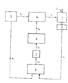
- the block diagram shows a stepper motor 1, the z. B. is designed as a unipolar stepper motor.
- a feedback 3 On the shaft 2 of the stepping motor 1 there is a feedback 3 which emits a signal s i in accordance with the number of steps carried out.
- the windings of the stepper motor 1 are fed by means of a signal S i from a power stage 4, the z. B. contains power switching transistors.
- a signal S i from a power stage 4
- the z. B. contains power switching transistors.
- Such an output stage and partly also the control are described in patent application A 938/84, patent ].
- the power stage is in turn controlled by a control generator 5, which generally has a complex electronic structure.
- a control generator 5 When used in connection with the control of diesel engines has this control generator one or more microcomputers, which present, depending on precisely measured values, such as engine speed, accelerator pedal position, air pressure, etc., and compared with stored, motor and / or driving zeugspez i fishing parameters output pulses Submit S b to performance level 4.
- the step frequency is also adapted to the respective requirements.
- a comparator is provided for this purpose, to which the output signal s i of the feedback unit 3 is supplied as an actual signal on the one hand and a set signal ss of the control generator 5 on the other hand.
- This target signal s 6 corresponds at least substantially to the output signal s b of the control generator 5 which is supplied to the power stage 4.
- the comparator 6 of the z. B. contains suitable counters, provides an error signal s f at its output if, within a certain time period, the number of steps performed by the stepping motor 1 is less than the number of steps specified by the control generator 5. In most cases, it will be the simplest and most expedient to design the comparator 6 as part of a microcomputer which is already available and is equipped with appropriate software.
- the error signal sf is fed via a timer 7, the function of which will be explained in more detail below, to a current setting stage 8, via whose output signal s a the magnitude of the motor current can be determined. If an error signal s f or sf 'is present (at the output of the timing element 7), the motor current is raised via the current setting stage 8 and the power stage 3 from a first predeterminable current value to a second current value which is clearly above the first value.
- the first current value is selected so that when operated with this current, the stepper motor is always operated below the limit of its continuous load capacity, even at high ambient temperatures.
- the second current value is so high that the stepper motor is supplied with power that is above its endurance.
- the motor can only be operated for a short time, especially at high ambient temperatures.
- the rise to the higher current value should take place quickly in order to lose as little time and steps as possible.
- the term "fast” is of course to be understood in connection with the different time constants of the shaft and control arrangement used. The increase does not have to be sudden, in practice it will often take place according to a staircase function or in a ramp shape.
- the timing element 7 enables an essentially undelayed increase in the output signal sa of the current setting stage 8, ie the signal sf 'occurs practically instantaneously with the error signal s f , the increased current value initially being maintained even after the error signal sf has disappeared.
- the timer 7, which will also be part of the current setting stage 8 can, the current is reduced again and - unless the loss of steps is then reported again - is kept at the low value.
- the dimensioning of both the stepper motor and the power level does not have to be based on the rarely occurring maximum power requirement, since a short-term overload is consciously accepted.
- the increased power requirement due to the increase in viscosity of the lubricants can also last longer, for B. ten minutes, but in this case the initially low temperature counteracts a possible thermal overload of the stepper motor and the power level.
- the current setting stage 6 or the timer 7 can also be set up using a microcomputer in such a way that the motor current which increases after step losses occur is slowly reduced after some time until the loss of steps is determined again and then on is kept a little above this current level, so that the current value required is maintained extremely economically.
- This value can also be stored so that the current value can be quickly changed back to the "optimum value" when the current is increased again briefly.
- the first and second current values are not to be understood as absolutely fixed values. These values can be particularly long-term, e.g. B. according to the prevailing temperature conditions, experience a predetermined change.
Landscapes
- Engineering & Computer Science (AREA)
- Power Engineering (AREA)
- Control Of Stepping Motors (AREA)
- Control Of Electric Motors In General (AREA)
- Protection Of Generators And Motors (AREA)
Claims (1)
- Montage de commande d'un moteur pas-à-pas (1 comportant un générateur de commande (5) destiné à produire des impulsions de commande pour le moteur pas-à-pas, un étage de puissance (4) branché en aval dudit générateur de signaux de commande pour l'alimentation du moteur pas-à-pas, un dispositif indicateur (3) accouplé mécaniquement au moteur pas-à-pas et appelé à produire un signal de valeur instantanée (s/j), un comparateur (6) destiné à comparer le nombre de pas défini par le signal de consigne (ss) du générateur de signaux de commande (5) au nombre de pas effectués défini par le signal de valeur instantané (s/j) dudit dispositif indicateur (3) et pour fournir un signal d'erreur (sf, s'f) lorsque les deux signaux d'entrée ne correspondent pas l'un à l'autre, ainsi qu'un étage de réglage de courant (8) qui est susceptible de recevoir à son entrée le signal d'erreur comparateur et de produire un signal de sortie (sa) déterminant la valeur du courant du moteur pas-à-pas (51) et transmis audit étage de puissance, caractérisé en ce qu'un organe de temporisation (7) est branché entre la sortie du comparateur (6) et l'entrée de l'étage de puissance (4) qui permet l'accroissement, sans retard notable, du signal de sortie (sa) d'une première valeur de courant prédéterminée jusqu'à une seconde valeur de courant supérieure à ladite première valeur, ainsi qu'une diminution retardée du signal de sortie vers la première valeur de courant.
Priority Applications (1)
| Application Number | Priority Date | Filing Date | Title |
|---|---|---|---|
| AT85890271T ATE48498T1 (de) | 1984-11-20 | 1985-10-30 | Schaltungsanordnung zur uberwachung eines schrittmotors. |
Applications Claiming Priority (2)
| Application Number | Priority Date | Filing Date | Title |
|---|---|---|---|
| DE3442373 | 1984-11-20 | ||
| DE19843442373 DE3442373A1 (de) | 1984-11-20 | 1984-11-20 | Schaltungsanordnung zur ueberwachung eines schrittmotors |
Publications (3)
| Publication Number | Publication Date |
|---|---|
| EP0182774A2 EP0182774A2 (fr) | 1986-05-28 |
| EP0182774A3 EP0182774A3 (en) | 1986-10-22 |
| EP0182774B1 true EP0182774B1 (fr) | 1989-12-06 |
Family
ID=6250755
Family Applications (1)
| Application Number | Title | Priority Date | Filing Date |
|---|---|---|---|
| EP85890271A Expired EP0182774B1 (fr) | 1984-11-20 | 1985-10-30 | Dispositif de surveillance pour un moteur pas à pas |
Country Status (4)
| Country | Link |
|---|---|
| EP (1) | EP0182774B1 (fr) |
| JP (1) | JPS61132099A (fr) |
| AT (1) | ATE48498T1 (fr) |
| DE (2) | DE3442373A1 (fr) |
Families Citing this family (7)
| Publication number | Priority date | Publication date | Assignee | Title |
|---|---|---|---|---|
| FR2648289B1 (fr) * | 1989-06-07 | 1991-09-06 | Valeo | Procede et dispositif de controle d'un moteur pas-a-pas |
| ES2071794T3 (es) * | 1989-06-07 | 1995-07-01 | Valeo Thermique Habitacle | Procedimiento y dispositivo de control de un motor paso a paso. |
| FR2662558B1 (fr) * | 1990-05-23 | 1992-07-24 | Valeo | Procede et dispositif de controle d'un moteur pas a pas. |
| EP0468920A1 (fr) * | 1990-07-26 | 1992-01-29 | Saia Ag | Dispositif de positionnement |
| DE10061787A1 (de) * | 2000-12-12 | 2002-06-13 | Siemens Building Tech Ag | Verfahren und Vorrichtung zur Überwachung von Schrittmotoren |
| FR3050309B1 (fr) * | 2016-04-15 | 2019-06-14 | Societe Technique Pour L'energie Atomique | Mecanisme d'entrainement d'absorbants de controle de reacteur nucleaire, procede de surveillance et reacteur nucleaire correspondants |
| CN113595455A (zh) * | 2021-06-21 | 2021-11-02 | 格力电器(武汉)有限公司 | 步进电机电控检测方法及系统 |
Family Cites Families (10)
| Publication number | Priority date | Publication date | Assignee | Title |
|---|---|---|---|---|
| DE2345416A1 (de) * | 1973-09-08 | 1975-03-20 | Maecker Elan Schaltelemente | Verfahren und vorrichtung zur schlupffreien nachlaufsteuerung von schrittmotoren |
| DD116996A1 (fr) * | 1974-11-28 | 1975-12-12 | ||
| US4187455A (en) * | 1975-08-04 | 1980-02-05 | United Technologies Corporation | Stepper motor feedback in position servo loop |
| DE2721630A1 (de) * | 1977-05-13 | 1979-03-01 | Olympia Werke Ag | Schaltungsanordnung zur ansteuerung eines schrittmotors nach dem chopper- prinzip |
| DE2805363A1 (de) * | 1978-02-09 | 1979-08-16 | Inst Flugnavigation Der Uni St | Vorrichtung zur kontrollierten steuerung eines schrittmotors |
| DD142777B1 (de) * | 1979-04-03 | 1984-12-05 | Riessland Eberhard Dipl Ing | Schaltungsanordnung zur verlustarmen ansteuerung von elektromagnetischen schrittantriebssystemen |
| FR2459579A1 (fr) * | 1979-06-21 | 1981-01-09 | Suisse Horlogerie | Detecteur d'avance d'un moteur pas a pas |
| US4349771A (en) * | 1979-09-26 | 1982-09-14 | Lucas Industries Limited | Stepper motor control circuit |
| DE3323106A1 (de) * | 1983-06-27 | 1985-01-10 | Siemens AG, 1000 Berlin und 8000 München | Verfahren und einrichtung zur bestimmung der position einer regelstange an einer einspritzpumpe fuer verbrennungsmotoren |
| EP0155932B1 (fr) * | 1984-03-20 | 1989-11-29 | VOEST-ALPINE AUTOMOTIVE Gesellschaft m.b.H. | Arrangement de circuit |
-
1984
- 1984-11-20 DE DE19843442373 patent/DE3442373A1/de not_active Ceased
-
1985
- 1985-10-30 DE DE8585890271T patent/DE3574651D1/de not_active Expired - Fee Related
- 1985-10-30 EP EP85890271A patent/EP0182774B1/fr not_active Expired
- 1985-10-30 AT AT85890271T patent/ATE48498T1/de not_active IP Right Cessation
- 1985-11-20 JP JP60260958A patent/JPS61132099A/ja active Pending
Also Published As
| Publication number | Publication date |
|---|---|
| ATE48498T1 (de) | 1989-12-15 |
| EP0182774A2 (fr) | 1986-05-28 |
| DE3442373A1 (de) | 1986-05-28 |
| EP0182774A3 (en) | 1986-10-22 |
| DE3574651D1 (de) | 1990-01-11 |
| JPS61132099A (ja) | 1986-06-19 |
Similar Documents
| Publication | Publication Date | Title |
|---|---|---|
| DE3416369C2 (de) | Vorrichtung zur Regelung der Geschwindigkeit eines Fahrzeugs | |
| DE2715408C2 (de) | Verfahren zum Betrieb und Regeleinrichtung für eine Brennkraftmaschine zum Konstanthalten wählbarer Drehzahlen | |
| DE2839669A1 (de) | Leerlaufdrehzahlsteuerung | |
| DE4420946B4 (de) | Steuersystem für die Kraftstoffzumessung bei einer Brennkraftmaschine | |
| DE102010040283B3 (de) | Verfahren zur Regelung der Einspritzmenge eines Piezoinjektors eines Kraftstoffeinspritzsystems | |
| DE19540921A1 (de) | System zur Steuerung einer Servokupplung | |
| DE1261354B (de) | Dieselmotor mit einem Stellglied zum Einstellen der Kraftstoffmenge und einem Regler | |
| DE2800433A1 (de) | Einrichtung zur drehzahlbegrenzung einer brennkraftmaschine | |
| EP0721692B1 (fr) | Convertisseur indirect | |
| DE2735596A1 (de) | Elektronische einspritzmengenregelung bei brennkraftmaschinen mit selbstzuendung | |
| DE10063080A1 (de) | Aktorsteuerung und zugehöriges Verfahren | |
| DE4129736C2 (de) | Fahrzeugsteuerungseinrichtung | |
| DE3531711C2 (fr) | ||
| DE1805050B2 (de) | Elektronische Regeleinrichtung für eine Brennkraftmaschine, insbesondere einen Dieselmotor | |
| DE4029537A1 (de) | Verfahren und vorrichtung zur steuerung und/oder regelung einer betriebsgroesse einer brennkraftmaschine | |
| DE3426698C2 (fr) | ||
| EP0182774A2 (fr) | Dispositif de surveillance pour un moteur pas à pas | |
| EP0283562B1 (fr) | Système de contrôle du ralenti pour un moteur à explosion | |
| DE3911708C2 (de) | Verfahren zum Betreiben einer Antriebseinheit | |
| DE3911706A1 (de) | Verfahren zum betreiben einer antriebseinheit | |
| DE3432757A1 (de) | Adaptive pi-dead-beat-regler fuer kraftfahrzeuge | |
| DE1136538B (de) | Brennstoffregelanlage fuer Gasturbinentriebwerke | |
| DE4303560B4 (de) | Verfahren und Vorrichtung zur Steuerung einer Verstelleinrichtung | |
| DE3512221A1 (de) | Elektronisch gesteuerter regler fuer dieselmotore | |
| DE4020654C2 (de) | Regelverfahren in Verbindung mit einer Brennkraftmaschine und/oder einem Kraftfahrzeug und Regelvorrichtung zur Durchführung des Regelverfahrens |
Legal Events
| Date | Code | Title | Description |
|---|---|---|---|
| PUAI | Public reference made under article 153(3) epc to a published international application that has entered the european phase |
Free format text: ORIGINAL CODE: 0009012 |
|
| AK | Designated contracting states |
Kind code of ref document: A2 Designated state(s): AT CH DE FR GB IT LI SE |
|
| PUAL | Search report despatched |
Free format text: ORIGINAL CODE: 0009013 |
|
| AK | Designated contracting states |
Kind code of ref document: A3 Designated state(s): AT CH DE FR GB IT LI SE |
|
| 17P | Request for examination filed |
Effective date: 19861210 |
|
| RAP1 | Party data changed (applicant data changed or rights of an application transferred) |
Owner name: VOEST-ALPINE AUTOMOTIVE GESELLSCHAFT MBH |
|
| 17Q | First examination report despatched |
Effective date: 19880419 |
|
| ITF | It: translation for a ep patent filed | ||
| GRAA | (expected) grant |
Free format text: ORIGINAL CODE: 0009210 |
|
| AK | Designated contracting states |
Kind code of ref document: B1 Designated state(s): AT CH DE FR GB IT LI SE |
|
| REF | Corresponds to: |
Ref document number: 48498 Country of ref document: AT Date of ref document: 19891215 Kind code of ref document: T |
|
| REF | Corresponds to: |
Ref document number: 3574651 Country of ref document: DE Date of ref document: 19900111 |
|
| ET | Fr: translation filed | ||
| GBT | Gb: translation of ep patent filed (gb section 77(6)(a)/1977) | ||
| PLBE | No opposition filed within time limit |
Free format text: ORIGINAL CODE: 0009261 |
|
| STAA | Information on the status of an ep patent application or granted ep patent |
Free format text: STATUS: NO OPPOSITION FILED WITHIN TIME LIMIT |
|
| 26N | No opposition filed | ||
| ITTA | It: last paid annual fee | ||
| EAL | Se: european patent in force in sweden |
Ref document number: 85890271.1 |
|
| PGFP | Annual fee paid to national office [announced via postgrant information from national office to epo] |
Ref country code: GB Payment date: 19960916 Year of fee payment: 12 |
|
| PGFP | Annual fee paid to national office [announced via postgrant information from national office to epo] |
Ref country code: FR Payment date: 19960920 Year of fee payment: 12 Ref country code: DE Payment date: 19960920 Year of fee payment: 12 Ref country code: CH Payment date: 19960920 Year of fee payment: 12 |
|
| PGFP | Annual fee paid to national office [announced via postgrant information from national office to epo] |
Ref country code: SE Payment date: 19960923 Year of fee payment: 12 Ref country code: AT Payment date: 19960923 Year of fee payment: 12 |
|
| PG25 | Lapsed in a contracting state [announced via postgrant information from national office to epo] |
Ref country code: GB Free format text: LAPSE BECAUSE OF NON-PAYMENT OF DUE FEES Effective date: 19971030 Ref country code: AT Free format text: LAPSE BECAUSE OF NON-PAYMENT OF DUE FEES Effective date: 19971030 |
|
| PG25 | Lapsed in a contracting state [announced via postgrant information from national office to epo] |
Ref country code: SE Free format text: LAPSE BECAUSE OF NON-PAYMENT OF DUE FEES Effective date: 19971031 Ref country code: LI Free format text: LAPSE BECAUSE OF NON-PAYMENT OF DUE FEES Effective date: 19971031 Ref country code: FR Free format text: THE PATENT HAS BEEN ANNULLED BY A DECISION OF A NATIONAL AUTHORITY Effective date: 19971031 Ref country code: CH Free format text: LAPSE BECAUSE OF NON-PAYMENT OF DUE FEES Effective date: 19971031 |
|
| REG | Reference to a national code |
Ref country code: CH Ref legal event code: PL |
|
| GBPC | Gb: european patent ceased through non-payment of renewal fee |
Effective date: 19971030 |
|
| PG25 | Lapsed in a contracting state [announced via postgrant information from national office to epo] |
Ref country code: DE Free format text: LAPSE BECAUSE OF NON-PAYMENT OF DUE FEES Effective date: 19980701 |
|
| EUG | Se: european patent has lapsed |
Ref document number: 85890271.1 |
|
| REG | Reference to a national code |
Ref country code: FR Ref legal event code: ST |