EP0182832B1 - Anlage und verfahren zum verschliessen von ventilsäcken - Google Patents
Anlage und verfahren zum verschliessen von ventilsäcken Download PDFInfo
- Publication number
- EP0182832B1 EP0182832B1 EP85902515A EP85902515A EP0182832B1 EP 0182832 B1 EP0182832 B1 EP 0182832B1 EP 85902515 A EP85902515 A EP 85902515A EP 85902515 A EP85902515 A EP 85902515A EP 0182832 B1 EP0182832 B1 EP 0182832B1
- Authority
- EP
- European Patent Office
- Prior art keywords
- valve
- bag
- glue
- valve bag
- oncoming
- Prior art date
- Legal status (The legal status is an assumption and is not a legal conclusion. Google has not performed a legal analysis and makes no representation as to the accuracy of the status listed.)
- Expired
Links
Images


Classifications
-
- B—PERFORMING OPERATIONS; TRANSPORTING
- B65—CONVEYING; PACKING; STORING; HANDLING THIN OR FILAMENTARY MATERIAL
- B65B—MACHINES, APPARATUS OR DEVICES FOR, OR METHODS OF, PACKAGING ARTICLES OR MATERIALS; UNPACKING
- B65B7/00—Closing containers or receptacles after filling
- B65B7/02—Closing containers or receptacles deformed by, or taking-up shape, of, contents, e.g. bags, sacks
- B65B7/025—Closing valve bags
-
- B—PERFORMING OPERATIONS; TRANSPORTING
- B65—CONVEYING; PACKING; STORING; HANDLING THIN OR FILAMENTARY MATERIAL
- B65D—CONTAINERS FOR STORAGE OR TRANSPORT OF ARTICLES OR MATERIALS, e.g. BAGS, BARRELS, BOTTLES, BOXES, CANS, CARTONS, CRATES, DRUMS, JARS, TANKS, HOPPERS, FORWARDING CONTAINERS; ACCESSORIES, CLOSURES, OR FITTINGS THEREFOR; PACKAGING ELEMENTS; PACKAGES
- B65D31/00—Bags or like containers made of paper and having structural provision for thickness of contents
- B65D31/14—Valve bags, i.e. with valves for filling
- B65D31/142—Valve bags, i.e. with valves for filling the filling port being formed by folding a flap connected to a side, e.g. block bottoms
Definitions
- the invention relates to a system according to the preamble of claim 1 and a method according to the preamble of claim 10.
- valve opening of the sack is pushed onto the supports of a filling machine, whereupon the contents are usually under the control of weighing by means of vibrating troughs, conveyor belts or the like. is filled into the sack.
- the remaining quantity of the filling material must be prevented from escaping as far as possible.
- Defensive Publication T941,002 (US-H-941 002) describes a system for the automatic closing of valve bags which are provided with an external valve, with a driven conveyor, a bag feed device and a closing station, which comprises an adhesive application device and a Has pressing device movable transversely to the conveyor for a valve bag part protruding from the outer valve and drive means for the pressing device and the adhesive application device.
- this shows a method for automatically closing valve bags which are provided with an external valve, are positioned after filling and are fed to a closing station, with a laterally projecting part of the external valve being folded up, folded over onto the adjacent floor area and pressed on after this Bottom area an adhesive has been applied in a track parallel to the folded edge of the outer valve and at a short distance from it.
- the station is designed so that purely further bags can run in during the closing process. The next sack can only be brought in when the gripper is free. This is a highly performance-inhibiting arrangement with poor machine utilization. For all these reasons, it is not surprising that an investment according to the defensive publication never appeared on the market.
- claims 1 and 10 advantageously result in an extremely powerful system for closing valve bags with an external valve protrusion.
- the gluing takes place in one pass.
- any stopping processes that conventionally result in a reduction in performance, material stress or even wear are eliminated.
- the system is very flexible because the relevant parameters can be changed within certain areas.
- the guides can be adjusted to the given bag dimensions, and the working paths of the adhesive application device and the pressing device can be optimally adapted to the respective conditions.
- the invention ensures the reliable closing of valve bags even with different filling and thus fluctuating dimensions, since it ensures that adequately shaped bags are brought in, which move quickly and quickly while the roller conveyor is running be closed cleanly and then immediately removed.
- the centerpiece of the system according to the invention is a closing station, in which the laterally protruding part of the outer valve is first folded up when the filled sack comes in, whereupon an adhesive zone of the sack bottom is provided with at least one glue trace and the outer valve and the protruding part are pressed onto it.
- the whole thing takes place automatically in a controllable cycle.
- the closing station has an in particular vertically movable adhesive application device and a driven rotary brush or elastic roller with a pressure equalization coating, which can be moved transversely to the roller conveyor, on which the filled bags are positioned and brought in and transported away after the valve has been closed.
- a preferably pneumatic drive with electrical or electronic control effects the individual work cycles through the organs mentioned.
- a heating device for a hot-melt adhesive can be connected to the line with this, unless a cold adhesive is used.
- Leveling rollers, possibly sliding elements and lateral guides, which can be adjustable individually or in groups or as a guide belt, are important for positioning the supplied bags.
- the valve bag 10 shown schematically in part in FIG. 1 has an outer valve 14 on one side on the bag bottom 12. Below this, a cover sheet 15 is led out laterally, which preferably extends to the side edge 20 of the folded, empty valve bag 10. Optionally or additionally, a shorter, outer tab 16 and an inner, longer tab 18 can be provided on the outer valve 14. If the sack 10 is filled, the side edge 20 disappears in the fold plane 22, which then also laterally delimits the bottom 12. Following the folding plane 22, the base 12 according to the invention has an adhesive zone 24.
- FIGS. 2a to 2d The method according to the invention for closing the external valve 14 is schematically illustrated in FIGS. 2a to 2d.
- the filled valve bag 10, which enters a closing station 40 (FIG. 3), is delimited laterally by the folding plane 22 and at the end by the bottom 12, the outer valve 14 projecting laterally (FIG. 2a).
- the outer valve 40 together with the overhang (15 or 18) is folded up (FIG. 2b).
- at least one adhesive track 26 is applied to the adhesive zone 24 (FIG. 2c).
- the external valve 14 is completely folded over by a pressure device (46, FIGS. 3 and 4a) and pressed together with its overhang (15 or 18) against the bag bottom 12 (FIG. 2d).
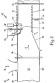
- the invention provides a system which is shown schematically in FIG. 3 and is designated 30 overall. It has a driven conveyor 32 or the like, a conveyor belt, a roller conveyor. can be and has a laterally arranged feed device 34 for filled valve bags. For the sake of clarity, these, like a supporting frame, typical fasteners, bearings and the like, are not shown.
- Lateral guides 36, 36 'and at least one leveling roller 38 which is fastened at an adjustable height above the conveyor 32 parallel to its plane, serve to position the valve sacks reaching the conveyor in the feed direction Z and conveying them lying in the conveying direction F to the closing station 40 will.
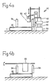
- a drain flap 60 which, when swiveled down, serves as a stop for the valve bag which has run in and brings it to a standstill (FIG. 4b).
- the closing station 40 has an adhesive application head 42, to which a sensor in the form of a wiper contact 52 is assigned. If a hot melt adhesive is used, a schematically indicated line leads from a heating device 44 the adhesive to the application head 42. This has at least one nozzle arranged in the conveying direction of the conveyor 32 in order to apply the adhesive track 26 on the adhesive zone 24 of the bag bottom 12 in addition to that in Running in to cause edged external valve 14.
- the closing station 40 contains guide means on both sides, e.g. B. rollers 54, each of which can be freely rotatably mounted in a (schematically indicated) frame. At least one group of the lateral guide rollers 54, as illustrated in FIG. 3 below, can be moved laterally in the direction of the arrow by means of, for example, a pneumatically actuated actuating device 58, in order to adapt the best possible way to the format of the filled valve bags to reach.
- Their inlet is supported by a preferably pivotable sliding plate 56, which is arranged upstream of the closing station 40 and at the same time causes or facilitates the positioning of each individual valve sack during the inlet under lateral guidance.
- the adhesive application device (which is shown in a middle position in FIG. 4 a) moves under the control of the wiper contact 52 from top to bottom along the sack bottom, expediently two adhesive traces 26 are applied in the adhesive zone 24. It is also possible and provided according to the invention to use a coiled or zigzag-shaped adhesive track 26 in a larger width of z. B. Apply 2 to 10 cm. As soon as the adhesive application device 42 has been raised again, the pressure roller or brush 46 is pushed out of the row of lateral guide rollers 34, the outer valve 14 including the projection 16 and 18 being pressed against the bag bottom 12.
- FIG. 5 A modified system design is shown in FIG. 5, with the omission of lateral boundaries, holding and switching elements, lines, etc., in order to make essential assemblies clear in a diagonal view.
- This system 30 has a frame R which carries a conveyor belt 32 with a drive roller 33, which conveyor belt preferably runs continuously during operation.
- Lateral guides 36, 36 'in the form of vertical plates are arranged on the front part.
- the guide plate 36 ' can be displaced transversely to the conveying direction F by means of an adjusting device 38, the incoming valve bag being moved towards the opposite guide plate 36 and at the same time being aligned and brought into a box shape.
- a swing flap 82 then strikes z. B. under the action of a photoelectrically controlled pressure cylinder 84 briefly on the bottom 12 with the valve 14 to be closed in order to even out the initially not flat bottom surface at least in the adhesive zone 24 and to align it substantially perpendicular to the plane of the conveyor 32.
- the actual closing station 40 in turn has an adhesive application head 42 (only indicated here) and a hot-melt device 44.
- the actuation of the application head 42 arranged on a first control roller 62 is effected via a sensing device.
- This has an angle lever 66 which carries the first control roller 62 and is connected to the piston rod of a lifting cylinder 68.
- a second control roller 64 is attached to a lever 70.
- a (not shown) curve segment on the lever 70 serves to couple the sequence of movements of the second control roller 64 with the angle lever 66 of the first control roller 62. This is initially higher than the top of the incoming valve bag 10, which pushes the second control roller 64 away in the conveying direction F. As a result, the first control roller 62 is unlocked.
- Both rollers 62, 64 now run over the top of the valve bag 10. This is conveyed further and the first control roller 62 engages on the bag bottom 12, a switch (not shown) being actuated for the start of the adhesive application. As soon as the first control roller 62 on the sack bottom 12 has reached the conveyor 32 (FIG. 6b), the adhesive application device 42 is switched off. It can be seen that there is also the possibility, by the distance of the control rollers 62, 64 from one another, for a given running speed of the conveyor 32, to define a period of time which can be used for controlling the adhesive application process.
- a similar control is provided for pressing the glued valve overhang.
- the pressure brush 46 is constantly driven by a motor 76 and, like this, is seated on a spring-loaded lever 80 which can be pivoted about a pivot bearing 74.
- Another pivot bearing 72 carries a lever roller 78 which is pushed aside by the incoming valve bag.
- the movement of the lever 80 is released, so that the pressure brush 46 rolls on the sack 10 conveyed along.
- the rotating brush 46 engages on the bag bottom 12.
- a switch (not shown) is actuated, whereby a pressure cylinder 48 briefly loads the pressure brush 46 in the conveying direction F.
- the adhesive is already set while the closed valve bag 10 is being conveyed.
- a pulse generator can be provided for the movement of the adhesive application device 42 and for the spraying out of the adhesive.
- the state of the adhesive and / or the working position (s) of the adhesive application device 42 can be monitored by means of a control device (not shown).
- valve bag 10 For filling the valve bag 10 are suitable sockets with a plug, which is inserted into the valve 14 and spread therein.
- a slight protrusion on the outer valve 14 is preferable because this makes handling easier.
- the outer valve 14 can be extended inwards, i.e. can be combined with an internal valve, so to speak.
- the system 30 can be combined with any type of filling system, the valve bags 10 being fed with the valve 14 arranged at the rear, as seen in the conveying direction F.
- the system 30 can therefore also be integrated into any existing filling system with vertical discharge of the valve bags 10 to be supplied.
- contactless and / or electronic control means can also be used instead of the control elements mentioned, e.g. B. photocells, optocouplers and the like.
- pure timers can be used for the time sequences, which cause switching operations in a programmed sequence.
- the program can be entered by a microprocessor and changed if necessary.
- the controller 30 (FIG. 3) or in the control box S (FIG. 3) there are by name adjustable clock generators for the pneumatic drives 48, 48 ', 68, 84.
- the time requirement of, for example, 2 s in the closing station 40 specifies in the exemplary embodiment in FIG. 3 the cycle in which the valve bags 10 are fed in, closed and transported away.
- the valve bags 10 on the continuously driven conveyor 32 also run continuously in the closing station 40 without being stopped.
Landscapes
- Engineering & Computer Science (AREA)
- Mechanical Engineering (AREA)
- Making Paper Articles (AREA)
- Package Closures (AREA)
- Bag Frames (AREA)
- Closing Of Containers (AREA)
- Separation By Low-Temperature Treatments (AREA)
- Manufacturing Of Steel Electrode Plates (AREA)
- Mechanically-Actuated Valves (AREA)
- Fertilizing (AREA)
- Catching Or Destruction (AREA)
- Medicines Containing Material From Animals Or Micro-Organisms (AREA)
Description
- Die Erfindung betrifft eine Anlage nach dem Oberbegriff von Anspruch 1 und ein Verfahren nach dem Oberbegriff von Anspruch 10.
- Seit Papier- und Polyäthylensäcke in Ventilausführung hergestellt werden, ist man bestrebt, einen dichten Ventilverschluß zu erreichen, insbesondere bei der automatischen Befüllung. Hierzu wird die Ventilöffnung des Sackes auf den Stützen einer Füllmaschine geschoben, worauf des Füllgut gewöhnlich unter Wäge-Kontrolle mittels Vibrationsrinnen, Förderbändern o.dgl. in den Sack abgefüllt wird. Beim Abzug von der Füllmaschine und vor allem danach muß das Austreten von Restmenge des Füllgutes möglichst verhindert werden.
- Das herkömmliche Umfalten einer äußeren Manschette ergibt zwar eine ausreichende Dichtigkeit, doch ist es umständlich und arbeitsintensiv, mithin teuer. Magnetventile beispielsweise nach Art der EP-B1-0 004 396 gewährleisten einen schnellen und dichten Verschluß, erfordern jedoch erhöhten Herstellungsaufwand. Verhältnismäßig langsam und ebenfalls aufwendig ist das bekannte Verfahren, Polyäthylen-Innenventile durch Ultraschall-Einwirkung zu verschweißen. Dasselbe gilt für die thermische oder UltraschallVerschweißung von Außenventilen aus Polyäthylen oder polyäthylenbeschichtetem Papier. Ferner hat man Heißschmelzkleber in Innenventilen angewandt, was jedoch gleichfalls verfahrenstechnisch ungünstig ist und überdies nicht ohne weiteres zu völlig zuverlässigem Verschluß führt.
- Die Defensive Publication T941,002 (US-H-941 002) beschreibt eine Anlage zum automatischen Verschließen von Ventilsäcken, die mit einem Außenventil versehen sind, mit einem angetriebenen Förderer, einer Sack-Zuführeinrichtung und einer Schließstation, die eine Kleber-Auftragseinrichtung und eine quer zu dem Förderer bewegliche Andrückvorrichtung für einen am Außenventil überstehenden Ventilsackteil sowie Antriebsmittel für die Andrückvorrichtung und die Kleber-Auftragseinrichtung aufweist. Ferner ist daraus ersichtlich ein Verfahren zum automatischen Verschließen von Ventilsäcken, die mit einem Außenventil versehen sind, nach dem Befüllen positioniert und einer Schließstation zugeführt werden, wobei ein seitlich überstehender Teil des Außenventils hochgekantet, auf den benachbarten Bodenbereich umgelegt und angedrückt wird, nachdem auf diesen Bodenbereich ein Kleber in einer Spur parallel zur Faltkante des Außenventils und in geringem Abstand zu ihr aufgetragen worden ist.
- Aus der genannten Veröffentlichung ergeben sich jedoch verschiedene, zum Teil gravierende Nachteile. So führt das Greifen des prallen Sacks mit Backen zu seiner Verformung. Er hat im Normalfalle nicht Kastenform mit verhältnismäßig klaren Kanten, sondern ist je nach Füllgut und Füllgrad mehr oder minder verbeult; dann läßt sich der Ventilüberstand nicht definiert abwinkeln, und der Ventilschlauch kann wegen seiner Eigenelastizität nicht ohne weiteres auf den Sackboden gedrückt werden. Ein hierfür vorgesehener Bügel kann allenfalls die in dieser Lage oberste Fläche glattstreichen, den Ventilüberstand jedoch höchstens bis zur Waagrechten abwinkeln. Anschließend soll das überstehende Ventilstück wohl zwischen den Drehteilen einer Klemmvorrichtung erfaßt werden. Damit das Ventil nicht abreißt, ist hierbei schonendste Krafteinwirkung und äußerst präzise Positionssteuerung notwendig, wodurch der praktische Konstruktionsaufwand stark in die Höhe getrieben wird. Im übrigen ist die Station so ausgebildet, daß während des Verschließens Rein weiterer Sack einlaufen kann. Erst wenn der Greifer frei ist, kann der nächste Sack herangeführt werden. Dies ist eine stark leistungshemmende Anordnung mit schlechter Maschinenausnutzung. Aus all diesen Gründen ist es nicht verwunderlich, daß eine Anlage gemäß der Defensive Publication auf dem Markt nie in Erscheinung getreten ist.
- Es ist ein wichtiges Ziel der Erfindung, die Nachteile des Standes der Technik mit möglichst wirtschaftlichen Mitteln zu überwinden und ein verbessertes, schnelles Verschließen des Füllventils zu erreichen. Namentlich soll eine Anlage von einfachem, übersichtlichem Aufbau geschaffen werden, um in neuartigem Verfahren das zuverlässige, rasche Verschließen von gefüllten Ventilsäcken bestimmter Ausbildung sicherzustellen.
- Die Hauptmerkmale der erfindungsgemäßen Anlage sind im kennzeichnenden Teil von Anspruch 1 angegeben. Ausgestaltungen sind Gegenstand der Ansprüche 2 bis 9. Die Grundschritte des Verfahrens nach der Erfindung sind in Anspruch 10 aufgeführt. Weiterbildungen hiervon sind in den Ansprüchen 11 bis 13 spezifiziert.
- Man erzielt durch die Merkmalskombinationen der Ansprüche 1 und 10 auf vorteilhafte Weise ein überaus leistungsfähiges System zum Verschließen von Ventilsäcken mit Außenventil- Überstand. Die Verklebung erfolgt im Durchlauf. Infolgedessen entfallen jegliche Anhaltevorgänge, die herkömmlich eine Leistungsminderung, eine Materialbelastung oder sogar Verschleiß bewirken. Die Anlage ist sehr flexibel, weil die maßgeblichen Parameter innerhalb gewisser Bereiche veränderbar sind. So lassen sich die Führungen auf die gegebenen Sackmaße einstellen, und die Arbeitswege der Kleber-Auftragseinrichtung sowie der Andrückvorrichtung können den jeweiligen Bedingungen optimal angepaßt werden. Mithin gewährleistet die Erfindung das zuverlässige Verschließen von Ventilsäcken auch bei unterschiedlicher Befüllung und somit schwankenden Abmessungen, da sie jeweils für das Heranführen hinreichend geformter Säcke sorgt, die bei laufender Rollenbahn rasch und sauber verschlossen werden und anschließend sogleich abtransportierbar sind.
- Kernstück der Anlage nach der Erfindung ist eine Schließstation, in welcher der seitlich überstehende Teil des Außenventils beim Einlaufen des gefüllten Sackes zunächst hochgekantet wird, worauf eine Klebezone des Sackbodens mit wenigstens einer Kleberspur versehen und das Außenventil samt überstehendem Teil daran angedrückt wird. Das Ganze vollzieht sich selbsttätig in steuerbarem Takt. Die Schließstation hat eine insbesondere vertikal verfahrbare Kleber-Auftragseinrichtung und eine angetriebene Rotationsbürste oder elastische Rolle mit Druckausgleichsbelag, die quer zu der Rollenbahn bewegbar ist, auf der die gefüllten Säcke positioniert und herangefürt sowie nach dem Verschließen des Ventils weggefördert werden. Ein vorzugsweise pneumatischer Antrieb mit elektrischer oder elektronischer Steuerung bewirkt die einzelnen Arbeitstakte durch die genannten Organe. Ein Fühler z. B. in Form eines Paares von Hebelrollen, eines Wischerkontakts o.dgl. steuert die Bewegung der Kleber-Auftragseinrichtung. Mit dieser kann eine Heizeinrichtung für einen Heißschmelzkleber leitungsverbunden sein, soferne nicht ein Kaltkleber verwendet wird. Für das Positionieren der zugeführten Säcke sind Egalisierrollen, gegebenenfalls bewegliche Gleitelemente und seitliche Führungen wichtig, die einzeln oder gruppenweise bzw. als Führungsband verstellbar sein können.
- Ausführungsbeispiele der Erfindung werden im folgenden anhand der Zeichnung erläutert. Darin zeigen:
- Fig. 1 eine Draufsicht auf einen leeren, flachliegenden Ventilsack,
- Fig. 2a schematisierte Draufsichten auf eine Außenventil bis 2b Anordnung des Ventilsackes gemäß Fig. 1 in verschiedenen Verfahrens-Stadien,
- Fig. 3 eine schematisierte Draufsicht auf eine Anlage,
- Fig. 4a eine schematisierte Seitenansicht einer Schließstation in der Anlage von Fig. 3,
- Fig. 4b eine Stirnansicht der Schließstation von Fig. 4a bzw. Fig. 3,
- Fig. 5 eine schematisierte Schrägansicht einer anderen Ausführungsform einer Anlage,
- Fig. 6a je eine schematische Seitenansicht eines Ventilsacks, und 6b der beim Einlaufen in die Schließstation Steuerrollen betätigt, und
- Fig. 6c eine schematische Draufsicht auf einen Teil einer Schließstation mit Ventilsack.
- Der in Fig. 1 schematisch zum Teil dargestellte Ventilsack 10 hat am Sackboden 12 einseitig ein Außenventil 14. Darunter ist ein Deckblatt 15 seitlich herausgeführt, das vorzugsweise bis zur Seitenkante 20 des zusammengefalteten, leeren Ventilsackes 10 reicht. Wahlweise oder zusätzlich kann am Außenventil 14 eine kürzere, äußere Lasche 16 und eine innere, längere Lasche 18 vorgesehen sein. Wird der Sack 10 gefüllt, so verschwindet die Seitenkante 20 in der Faltebene 22, welche dann zugleich den Boden 12 seitlich begrenzt. Anschließend an die Faltebene 22 hat der Boden 12 nach der Erfindung eine Klebezone 24.
- In den Fig. 2a bis 2d ist das erfindungsgemäße Verfahren zum Verschließen des Außenventils 14 schematisch veranschaulicht. Der gefüllte, in eine Schließstation 40 (Fig. 3) einlaufende Ventilsack 10 ist seitlich von der Faltebene 22 und stirnseitig vom Boden 12 begrenzt, wobei das Außenventil 14 seitlich übersteht (Fig. 2a). Durch das Einlaufen in die Schließstation 40 wird das Außenventil 40 samt Überstand (15 bzw. 18) hochgekantet (Fig. 2b). Während der Ventilsack 10 nun stillsteht, wird wenigstens eine Kleberspur 26 auf die Klebezone 24 aufgetragen (Fig. 2c). Im nächsten Schritt wird durch eine Andrückvorrichtung (46, Fig. 3 und Fig. 4a) das Außenventil 14 vollends umgelegt und samt seinem Überstand (15 bzw. 18) an den Sackboden 12 angedrückt (Fig. 2d).
- Zur Durchführung dieses Verfahrens sieht die Erfindung eine Anlage vor, die in Fig. 3 schematisch dargestellt und insgesamt mit 30 bezeichnet ist. Sie hat einen angetriebenen Förderer 32, der ein Förderband, eine Rollenbahn o.dgl. sein kann und eine seitlich angeordnete Zuführeinrichtung 34 für gefüllte Ventilsäcke aufweist. Diese sind, ebenso wie ein tragender Rahmen, typische Befestigungsmittel, Lagerungen u.dgl., der Übersichtlichkeit halber nicht eingezeichnet.
- Seitliche Führungen 36, 36' und wenigstens eine Egalisierrolle 38, die in einstellbarem Höhenabstand über dem Förderer 32 parallel zu seiner Ebene befestigt ist, dienen zum Positionieren der in Zuführrichtung Z auf den Förderer gelangenden Ventilsäcke, die darauf liegend in Förderrichtung F zur Schließstation 40 befördert werden. An deren Ende befindet sich eine Ablaufklappe 60, die heruntergeschwenkt als Anschlag für den eingelaufenen Ventilsack dient und ihn zum Stillstand bringt (Fig. 4b).
- Die Schließstation 40 weist einen Kleber-Auftragskopf 42 auf, dem ein Fühler in Form eines Wischerkontakts 52 zugeordnet ist. Wird ein Heißschmelzkleber verwendet, so führt eine schematisiert angedeutete Leitung aus einer Heizeinrichtung 44 den Kleber an den Auftragskopf 42. Dieser hat wenigstens eine in Förderrichtung des Förderers 32 angeordnete Düse, um den Auftrag der Kleberspur 26 auf der Klebezone 24 des Sackbodens 12 neben dem beim Einlaufen hochgekanteten Außenventil 14 zu bewirken.
- Ferner enthält die Schließstation 40 beiderseits Führungsmittel, z. B. Rollen 54, die jeweils in einem (schematisch angedeuteten) Rahmen frei drehbar gelagert sein können. Zumindest eine Gruppe der seitlichen Führungsrollen 54 ist, wie in Fig. 3 unten veranschaulicht, mittels einer beispielsweise pneumatisch betätigten Stelleinrichtung 58 in Pfeilrichtung seitlich bewegbar, um die bestmögliche Anpassung an das Format der gefüllten Ventilsäcke zu erreichen. Deren Einlauf wird durch ein vorzugsweise schwenkbares Gleitblech 56 unterstützt, das der Schließstation 40 vorgeordnet ist und zugleich die Positionierung jedes einzelnen Ventilsacks beim Einlauf unter seitlicher Führung bewirkt bzw. erleichtert.
- Unter den normalerweise lagefest angeordneten Führungsrollen 54 befindet sich am Anfang der Schließstation 40 eine elastische Andrückrolle oder -bürste 46, die von einem pneumatischen Antrieb 48 quer zur Laufrichtung der Rollenbahn 32 bewegbar ist. Ein anderer pneumatischer Antrieb 48' bewirkt die vertikale Bewegung des Kleber-Auftragskopfes 42. Eine schematisch angedeutete elektrisch-pneumatische Steuerung 50 sorgt für die taktmäßige Bewegung der Antriebe 48,48'.
- Ist ein Ventilsack 10 in die Schließstation 40 eingefahren und dabei sein Außenventil 14 hochgeschwenkt worden, so fährt die Kleber-Auftragseinrichtung (die in Fig.4a in einer mittleren Position dargestellt ist) unter Steuerung durch den Wischerkontakt 52 von oben nach unten am Sackboden entlang, wobei zweckmäßig zwei Kleberspuren 26 in der Klebezone 24 aufgetragen werden. Es ist auch möglich und erfindungsgemäß vorgesehen, eine gewendelte oder zickzackförmige Kleberspur 26 in größerer Breite von z. B. 2 bis 10 cm aufzutragen. Sobald die Kleber-Auftragseinrichtung 42 wieder hochgefahren ist, wird die Andrückrolle oder -bürste 46 aus der Reihe der seitlichen Führungsrollen 34 heraus vorgeschoben, wobei das Außenventil 14 samt Überstand 16 bzw. 18 an den Sackboden 12 angedrückt wird. Indem das Andrückelement 46 vor und zurück bewegt wird, ergibt sich über die ganze Bodenbreite ein sicheres Anliegen des verklebten Deckblattes 13 bzw. der inneren Lasche 18 an der Kleberspur 26. Ein breiterer oder ein zusätzlicher Kleberauftrag 28 (Fig. 2d) kann auch die äußere Lasche 16 festlegen. Durch das Verkleben des Deckblattes 13 und/oder der äußeren Lasche 16 wird ein sog. Daumenausschlag verhindert.
- Eine abgewandelte Anlagengestaltung zeigt Fig. 5, unter Weglassung von seitlichen Begrenzungen, Halte- und Schaltelementen, Leitungen usw., um in schematisierter Schrägansicht wesentliche Baugruppen deutlich werden zu lassen. Diese Anlage 30 weist einen Rahmen R auf, der ein im Betrieb vorzugsweise ständig laufendes Förderband 32 mit Antriebsrolle 33 trägt. Am Vorderteil sind seitliche Führungen 36, 36' in Form von senkrechten Platten angeordnet. Die Führungsplatte 36' kann mittels einer Stelleinrichtung 38 quer zur Förderrichtung F verschoben werden, wobei der einlaufende Ventilsack auf die gegenüberliegende Führungsplatte 36 zu bewegt und zugleich ausgerichtet sowie auf Kastenform gebracht wird. Eine Schwenkklappe 82 schlägt sodann z. B. unter der Einwirkung eines fotoelektrisch gesteuerten Druckzylinders 84 kurz auf den Boden 12 mit dem zu verschließenden Ventil 14 auf, um die zunächst noch nicht ebene Bodenfläche zumindest in der Klebezone 24 zu vergleichmäßigen und im wesentlichen senkrecht zur Ebene des Förderers 32 auszurichten.
- Die eigentliche Schließstation 40 hat wiederum einen (hier lediglich angedeuteten) Kleber-Auftragskopf 42 und eine Heißschmelzeinrichtung 44. Die Betätigung des an einer ersten Steuerrolle 62 angeordneten Auftragskopfes 42 wird über eine Fühleinrichtung bewirkt. Diese weist einen Winkelhebel 66 auf, der die erste Steuerrolle 62 trägt und mit der Kolbenstange eines Hubzylinders 68 verbunden ist. An einem Hebel 70 ist eine zweite Steuerrolle 64 befestigt. Ein (nicht gezeichnetes) Kurvensegment am Hebel 70 dient zur Koppelung des Bewegungsablaufs der zweiten Steuerrolle 64 mit dem Winkelhebel 66 der ersten Steuerrolle 62. Diese steht zunächst höher als die Oberseite des einlaufenden Ventilsacks 10, der die zweite Steuerrolle 64 in Förderrichtung F wegdrückt. Dadurch wird die erste Steuerrolle 62 entarretiert. Beide Rollen 62, 64 laufen nun über die Oberseite des Ventilsacks 10. Dieser wird weitergefördert und die erste Steuerrolle 62 fällt an dem Sackboden 12 ein, wobei ein (nicht dergestellter) Schalter für den Beginn des Kleber-Auftrags betätigt wird. Sobald die erste Steuerrolle 62 am Sackboden 12 bis zum Förderer 32 heruntergelangt ist (Fig. 6b), wird die Kleber-Auftragseinrichtung 42 abgeschaltet. Man erkennt, daß auch die Möglichkeit besteht, durch den Abstand der Steuerrollen 62, 64 voneinander bei gegebener Laufgeschwindigkeit des Förderers 32 einen Zeitraum zu definieren, der sich für die Steuerung des Kleber-Auftragsvorganges ausnutzen läßt.
- Eine ähnliche Steuerung ist für das Anpressen des verklebten Ventil-Überstandes vorgesehen. Die Andrückbürste 46 wird von einem Motor 76 ständig angetrieben und sitzt wie dieser auf einem federbelasteten Hebel 80, der um ein Drehlager 74 schwenkbar ist. Ein weiteres Drehlager 72 trägt eine Hebelrolle 78, die vom einlaufenden Ventilsack zur Seite gedrückt wird. Dadurch wird die Bewegung des Hebels 80 freigegeben, so daß die Andrückbürste 46 an dem entlanggeförderten Sack 10 abrollt. Am Sackboden 12 fällt die rotierende Bürste 46 ein. Dabei wird ein (nicht gezeichneter) Schalter betätigt, wodurch ein Druckzylinder 48 die Andrückbürste 46 in Förderrichtung F kurzzeitig belastet. Bereits während der verschlossene Ventilsack 10 weitergefördert wird, erfolgt das Abbinden des Klebers.
- In den Rahmen der Erfindung fallen zahlreiche Abwandlungen. So kann für die Bewegung der Kleber-Auftragseinrichtung 42 und für das Ausspritzen des Klebers ein Impulsgeber vorgesehen sein. Die Überwachung des Kleberzustandes und/oder der Arbeitsposition(en) der Kleber-Auftragseinrichtung 42 kann mittels einer (nicht dargestellten) Kontrolleinrichtung erfolgen.
- Für gehobene Dichtigkeits-Ansprüche kann es in Betracht kommen, den Sackboden 12 in der Klebezone 24 mit einer Trockenklebeschicht zu versehen und den Arbeitsgang des Auftragens von Kleber oder Leimmittel der Einrichtung 26 durch thermofixierendes Andrücken z. B. mittels einer Anpreßrolle zu ersetzen. Es ist ferner möglich, an der Klebestelle einen Zweikomponenten-Kleber kurzer Aushärtezeit anzubringen, wenn es darauf ankommt, das Abbinden besonders schnell und sicher zu bewirken. Sofern als Andrückvorrichtung 46 eine Rolle verwendet wird, ist eine elastische Auflage z. B. aus Moosgummi vorgesehen; ansonsten ist eine mit Naturborsten besetzte, angetriebene Rotationsbürste bevorzugt.
- Zum Befüllen des Ventilsackes 10 eignen sich Stutzen mit einem Aufstecker, der in das Ventil 14 eingeführt und darin gespreizt wird. Allgemein ist ein geringer Überstand am Außenventil 14 vorzuziehen, weil das die Handhabung erleichtert. Für Fälle, wo es insgesamt zu kurz wäre und mit einem Produktaustritt gerechnet werden müßte, kann das Außenventil 14 nach innen verlängert, d.h. sozusagen mit einem Innenventil kombiniert werden.
- Es ist auch möglich und erfindungsgemäß vorgesehen, daß zwei Füllstraßen zusammengeführt werden und eine gemeinsame schließstation anlaufen. Die Anlage 30 läßt sich mit Abfüllanlagen beliebiger Art kombinieren, wobei die Ventilsäcke 10 mit - in Förderrichtung F gesehen - hinten angeordnetem Ventil 14 liegend zugeführt werden. Die Anlage 30 kann daher auch in jede bestehende Abfüllanlage mit Senkrechtabwurf der zuzuführenden Ventilsäcke 10 integriert werden.
- Allgemein können anstelle der erwähnten Steuerungselemente auch berührungslos arbeitende und/oder elektronische Steuermittel eingesetzt werden, z. B. Fotozellen, Optokoppler u.dgl. Ferner sind für die Zeitabläufe reine Timer verwendbar, die in programmierter Folge Schaltvorgänge bewirken. Das Programm kann durch einen Mikroprozessor eingegeben und gegebenafalls verändert werden.
- In der Steuerung 30 (Fig. 3) bzw. im Steuerkasten S (Fig. 3) sind namentlich einstellbare Taktgeber für die pneumatischen Antriebe 48,48', 68,84 vorhanden. Der Zeitbedarf von beispielsweise 2 s in der Schließstation 40 gibt im Ausführungsbeispiel der Fig. 3 den Takt vor, in welchem die Ventilsäcke 10 zugeführt, verschlossen und abtransportiert werden. In der Ausführungsform gemäß Fig. 3 laufen die Ventilsäcke 10 auf dem ständig angetriebenen Förderer 32 auch in der Schließstation 40 kontinuierlich durch, ohne angehalten zu werden.
Claims (15)
Priority Applications (1)
| Application Number | Priority Date | Filing Date | Title |
|---|---|---|---|
| AT85902515T ATE32586T1 (de) | 1984-05-10 | 1985-05-09 | Anlage und verfahren zum verschliessen von ventilsaecken. |
Applications Claiming Priority (2)
| Application Number | Priority Date | Filing Date | Title |
|---|---|---|---|
| EP84105278A EP0160725A1 (de) | 1984-05-10 | 1984-05-10 | Ventilsäcke sowie Anlage und Verfahren zum Verschliessen von Ventilsäcken |
| EP84105278 | 1984-05-10 |
Publications (2)
| Publication Number | Publication Date |
|---|---|
| EP0182832A1 EP0182832A1 (de) | 1986-06-04 |
| EP0182832B1 true EP0182832B1 (de) | 1988-02-24 |
Family
ID=8191934
Family Applications (2)
| Application Number | Title | Priority Date | Filing Date |
|---|---|---|---|
| EP84105278A Withdrawn EP0160725A1 (de) | 1984-05-10 | 1984-05-10 | Ventilsäcke sowie Anlage und Verfahren zum Verschliessen von Ventilsäcken |
| EP85902515A Expired EP0182832B1 (de) | 1984-05-10 | 1985-05-09 | Anlage und verfahren zum verschliessen von ventilsäcken |
Family Applications Before (1)
| Application Number | Title | Priority Date | Filing Date |
|---|---|---|---|
| EP84105278A Withdrawn EP0160725A1 (de) | 1984-05-10 | 1984-05-10 | Ventilsäcke sowie Anlage und Verfahren zum Verschliessen von Ventilsäcken |
Country Status (8)
| Country | Link |
|---|---|
| EP (2) | EP0160725A1 (de) |
| AT (1) | ATE32586T1 (de) |
| AU (1) | AU4401085A (de) |
| DE (1) | DE3561645D1 (de) |
| DK (1) | DK596685A (de) |
| FI (1) | FI78270C (de) |
| NO (1) | NO853792L (de) |
| WO (1) | WO1985005341A1 (de) |
Families Citing this family (2)
| Publication number | Priority date | Publication date | Assignee | Title |
|---|---|---|---|---|
| DE8805854U1 (de) * | 1988-05-03 | 1988-06-16 | Teutrine, Annemarie, 4740 Oelde | Vorrichtung zum Verschließen eines Ventilsacks |
| WO2002087977A2 (en) * | 2001-05-02 | 2002-11-07 | Hood Packaging Corporation | Sealable valve bag and manufacturing method therefor |
Family Cites Families (7)
| Publication number | Priority date | Publication date | Assignee | Title |
|---|---|---|---|---|
| DE928930C (de) * | 1949-06-27 | 1955-06-13 | Richard Mundhenke | Als Kreuzbodenventilsack ausgebildeter Warenbeutel fuer Haushaltspackungen |
| DE1194313B (de) * | 1957-09-10 | 1965-06-03 | Continental Oil Co | Selbsttaetige Beleim- und Verschliessvorrichtung fuer Ventilsaecke |
| SE332384B (de) * | 1968-02-09 | 1971-02-01 | Billeruds Ab | |
| UST941002I4 (en) * | 1974-06-28 | 1975-12-02 | Apparatus for automatically sealing valve bags | |
| NL7414208A (nl) * | 1974-10-30 | 1976-05-04 | Wavin Bv | Werkwijze voor de vervaardiging van zakken uit kunststof materiaal. |
| US4026237A (en) * | 1975-10-01 | 1977-05-31 | Emhart Industries, Inc. | Apparatus for applying hot melt glue to a surface of an object |
| IT1100598B (it) * | 1978-11-27 | 1985-09-28 | Ocme Spa | Dispositivo per l'incollaggio di un lembo di scatole di cartone su un lato frontale durante il trasporto continuo delle scatole stesse |
-
1984
- 1984-05-10 EP EP84105278A patent/EP0160725A1/de not_active Withdrawn
-
1985
- 1985-05-09 AT AT85902515T patent/ATE32586T1/de active
- 1985-05-09 AU AU44010/85A patent/AU4401085A/en not_active Abandoned
- 1985-05-09 WO PCT/EP1985/000215 patent/WO1985005341A1/de not_active Ceased
- 1985-05-09 DE DE8585902515T patent/DE3561645D1/de not_active Expired
- 1985-05-09 EP EP85902515A patent/EP0182832B1/de not_active Expired
- 1985-09-26 NO NO853792A patent/NO853792L/no unknown
- 1985-12-02 FI FI854758A patent/FI78270C/fi not_active IP Right Cessation
- 1985-12-20 DK DK596685A patent/DK596685A/da not_active Application Discontinuation
Also Published As
| Publication number | Publication date |
|---|---|
| ATE32586T1 (de) | 1988-03-15 |
| FI854758A7 (fi) | 1985-12-02 |
| NO853792L (no) | 1985-12-05 |
| AU4401085A (en) | 1985-12-13 |
| DK596685D0 (da) | 1985-12-20 |
| DK596685A (da) | 1985-12-20 |
| EP0160725A1 (de) | 1985-11-13 |
| FI854758A0 (fi) | 1985-12-02 |
| EP0182832A1 (de) | 1986-06-04 |
| FI78270C (fi) | 1989-07-10 |
| FI78270B (fi) | 1989-03-31 |
| WO1985005341A1 (fr) | 1985-12-05 |
| DE3561645D1 (en) | 1988-03-31 |
Similar Documents
| Publication | Publication Date | Title |
|---|---|---|
| DE4100694C2 (de) | Anlage zur Herstellung von Isolierglasscheiben | |
| EP2666728B1 (de) | Etikettierer und Verfahren zum Etikettieren | |
| DE1561966A1 (de) | Verfahren und Vorrichtung zum Verpacken von Waren | |
| DE3123194C2 (de) | ||
| DE2609729A1 (de) | Steuervorrichtung fuer den anhebbaren kopfteil einer kartonverschliessmaschine | |
| DE2642490A1 (de) | Vorrichtung zur ueberfuehrung von gegenstaenden mit einem vorbestimmten abstand auf einen aufnahmefoerderer | |
| DE3715445A1 (de) | Verfahren und vorrichtung zur aufbringung eines traggriffes beim automatischen verpacken von kartons | |
| EP0182832B1 (de) | Anlage und verfahren zum verschliessen von ventilsäcken | |
| DE1586093B2 (de) | Vorrichtung zum aufbringen von aufreisstreifen auf ein einschlagmaterialband | |
| DE102019110567A1 (de) | Haftmittelauftragseinrichtung | |
| EP0344363B1 (de) | Vorrichtung zum Ausrichten und Öffnen flachliegender Kunststoffsäcke | |
| DE3521951C2 (de) | ||
| DE2629308A1 (de) | Verfahren zur herstellung von beuteln und einrichtung zur automatischen durchfuehrung dieses verfahrens | |
| DE2939899C2 (de) | Verfahren und Vorrichtung zum Öffnen von Faserballen | |
| DE3442943A1 (de) | Vorrichtung zum falten der oeffnung von gefuellten saecken | |
| DE8660022U1 (de) | Vorrichtung zum Verschließen von Ventilsäcken | |
| DE19538166C2 (de) | Vorrichtung und Verfahren zum kontinuierlichen Beleimen von Faltschachtelzuschnitten | |
| EP4029791B1 (de) | Ansteuerung greiferschlitten | |
| DE2212860A1 (de) | Maschine zum selbsttaetigen Herstellen von auf blattfoermigen Traegern befestigten Stoffmusterfolgen | |
| EP0006249B1 (de) | Vorrichtung zum Überziehen eines Schlauches aus wärmeschrumpffähigem Kunststoff über einen Gutstapel | |
| DE1217842B (de) | Verfahren und Vorrichtung zum Verschliessen von Kartons | |
| DE2520203C2 (de) | Vorrichtung zum Herstellen und Füllen von Beuteln aus einer Verpackungsmaterialbahn | |
| DE2556968A1 (de) | Maschine zum herstellen von beuteln aus thermoplastischen folienbahnen | |
| DE1411693C (de) | Vorrichtung zum Herstellen von Bucheinbänden | |
| DE1922432A1 (de) | Maschine zum Anbringen von Lesezeichen an gehefteten Buchbloecken |
Legal Events
| Date | Code | Title | Description |
|---|---|---|---|
| PUAI | Public reference made under article 153(3) epc to a published international application that has entered the european phase |
Free format text: ORIGINAL CODE: 0009012 |
|
| 17P | Request for examination filed |
Effective date: 19860108 |
|
| AK | Designated contracting states |
Kind code of ref document: A1 Designated state(s): AT BE CH DE FR GB IT LI LU NL SE |
|
| 17Q | First examination report despatched |
Effective date: 19861210 |
|
| GRAA | (expected) grant |
Free format text: ORIGINAL CODE: 0009210 |
|
| AK | Designated contracting states |
Kind code of ref document: B1 Designated state(s): AT BE CH DE FR GB IT LI LU NL SE |
|
| REF | Corresponds to: |
Ref document number: 32586 Country of ref document: AT Date of ref document: 19880315 Kind code of ref document: T |
|
| REF | Corresponds to: |
Ref document number: 3561645 Country of ref document: DE Date of ref document: 19880331 |
|
| ET | Fr: translation filed | ||
| GBT | Gb: translation of ep patent filed (gb section 77(6)(a)/1977) | ||
| ITF | It: translation for a ep patent filed | ||
| PLBE | No opposition filed within time limit |
Free format text: ORIGINAL CODE: 0009261 |
|
| STAA | Information on the status of an ep patent application or granted ep patent |
Free format text: STATUS: NO OPPOSITION FILED WITHIN TIME LIMIT |
|
| 26N | No opposition filed | ||
| ITTA | It: last paid annual fee | ||
| PGFP | Annual fee paid to national office [announced via postgrant information from national office to epo] |
Ref country code: GB Payment date: 19920424 Year of fee payment: 8 |
|
| PGFP | Annual fee paid to national office [announced via postgrant information from national office to epo] |
Ref country code: SE Payment date: 19920512 Year of fee payment: 8 Ref country code: FR Payment date: 19920512 Year of fee payment: 8 Ref country code: CH Payment date: 19920512 Year of fee payment: 8 |
|
| PGFP | Annual fee paid to national office [announced via postgrant information from national office to epo] |
Ref country code: LU Payment date: 19920513 Year of fee payment: 8 |
|
| PGFP | Annual fee paid to national office [announced via postgrant information from national office to epo] |
Ref country code: AT Payment date: 19920514 Year of fee payment: 8 |
|
| PGFP | Annual fee paid to national office [announced via postgrant information from national office to epo] |
Ref country code: BE Payment date: 19920519 Year of fee payment: 8 |
|
| PGFP | Annual fee paid to national office [announced via postgrant information from national office to epo] |
Ref country code: NL Payment date: 19920531 Year of fee payment: 8 |
|
| PGFP | Annual fee paid to national office [announced via postgrant information from national office to epo] |
Ref country code: DE Payment date: 19920718 Year of fee payment: 8 |
|
| EPTA | Lu: last paid annual fee | ||
| PG25 | Lapsed in a contracting state [announced via postgrant information from national office to epo] |
Ref country code: LU Free format text: LAPSE BECAUSE OF NON-PAYMENT OF DUE FEES Effective date: 19930509 Ref country code: GB Effective date: 19930509 Ref country code: AT Effective date: 19930509 |
|
| PG25 | Lapsed in a contracting state [announced via postgrant information from national office to epo] |
Ref country code: SE Effective date: 19930510 |
|
| PG25 | Lapsed in a contracting state [announced via postgrant information from national office to epo] |
Ref country code: LI Effective date: 19930531 Ref country code: CH Effective date: 19930531 Ref country code: BE Effective date: 19930531 |
|
| BERE | Be: lapsed |
Owner name: WALTER DURBECK PAPIERSACKFABRIKEN G.M.B.H. & CO. Effective date: 19930531 |
|
| PG25 | Lapsed in a contracting state [announced via postgrant information from national office to epo] |
Ref country code: NL Effective date: 19931201 |
|
| GBPC | Gb: european patent ceased through non-payment of renewal fee |
Effective date: 19930509 |
|
| NLV4 | Nl: lapsed or anulled due to non-payment of the annual fee | ||
| PG25 | Lapsed in a contracting state [announced via postgrant information from national office to epo] |
Ref country code: FR Effective date: 19940131 |
|
| REG | Reference to a national code |
Ref country code: CH Ref legal event code: PL |
|
| PG25 | Lapsed in a contracting state [announced via postgrant information from national office to epo] |
Ref country code: DE Effective date: 19940201 |
|
| REG | Reference to a national code |
Ref country code: FR Ref legal event code: ST |
|
| EUG | Se: european patent has lapsed |
Ref document number: 85902515.7 Effective date: 19931210 |