EP0182923B1 - Appareil pour l'exercice de sports nautiques - Google Patents
Appareil pour l'exercice de sports nautiques Download PDFInfo
- Publication number
- EP0182923B1 EP0182923B1 EP84114072A EP84114072A EP0182923B1 EP 0182923 B1 EP0182923 B1 EP 0182923B1 EP 84114072 A EP84114072 A EP 84114072A EP 84114072 A EP84114072 A EP 84114072A EP 0182923 B1 EP0182923 B1 EP 0182923B1
- Authority
- EP
- European Patent Office
- Prior art keywords
- water
- container
- sport apparatus
- pool
- rising
- Prior art date
- Legal status (The legal status is an assumption and is not a legal conclusion. Google has not performed a legal analysis and makes no representation as to the accuracy of the status listed.)
- Expired
Links
- XLYOFNOQVPJJNP-UHFFFAOYSA-N water Substances O XLYOFNOQVPJJNP-UHFFFAOYSA-N 0.000 claims abstract description 142
- 230000000630 rising effect Effects 0.000 claims abstract description 27
- 230000009182 swimming Effects 0.000 description 10
- 238000000034 method Methods 0.000 description 6
- 238000010992 reflux Methods 0.000 description 4
- 238000005192 partition Methods 0.000 description 3
- 230000007704 transition Effects 0.000 description 2
- 230000001133 acceleration Effects 0.000 description 1
- 230000004888 barrier function Effects 0.000 description 1
- 230000015572 biosynthetic process Effects 0.000 description 1
- 230000015556 catabolic process Effects 0.000 description 1
- 230000003111 delayed effect Effects 0.000 description 1
- 230000000694 effects Effects 0.000 description 1
- 230000005484 gravity Effects 0.000 description 1
- 238000009434 installation Methods 0.000 description 1
- 239000007788 liquid Substances 0.000 description 1
- JTJMJGYZQZDUJJ-UHFFFAOYSA-N phencyclidine Chemical compound C1CCCCN1C1(C=2C=CC=CC=2)CCCCC1 JTJMJGYZQZDUJJ-UHFFFAOYSA-N 0.000 description 1
- 238000005381 potential energy Methods 0.000 description 1
- 238000002360 preparation method Methods 0.000 description 1
- 238000005086 pumping Methods 0.000 description 1
- 230000001105 regulatory effect Effects 0.000 description 1
- 238000000926 separation method Methods 0.000 description 1
- 239000007787 solid Substances 0.000 description 1
- 238000011144 upstream manufacturing Methods 0.000 description 1
Images


Classifications
-
- A—HUMAN NECESSITIES
- A63—SPORTS; GAMES; AMUSEMENTS
- A63G—MERRY-GO-ROUNDS; SWINGS; ROCKING-HORSES; CHUTES; SWITCHBACKS; SIMILAR DEVICES FOR PUBLIC AMUSEMENT
- A63G31/00—Amusement arrangements
- A63G31/007—Amusement arrangements involving water
-
- A—HUMAN NECESSITIES
- A63—SPORTS; GAMES; AMUSEMENTS
- A63B—APPARATUS FOR PHYSICAL TRAINING, GYMNASTICS, SWIMMING, CLIMBING, OR FENCING; BALL GAMES; TRAINING EQUIPMENT
- A63B69/00—Training appliances or apparatus for special sports
- A63B69/0093—Training appliances or apparatus for special sports for surfing, i.e. without a sail; for skate or snow boarding
-
- A—HUMAN NECESSITIES
- A63—SPORTS; GAMES; AMUSEMENTS
- A63B—APPARATUS FOR PHYSICAL TRAINING, GYMNASTICS, SWIMMING, CLIMBING, OR FENCING; BALL GAMES; TRAINING EQUIPMENT
- A63B69/00—Training appliances or apparatus for special sports
- A63B69/12—Arrangements in swimming pools for teaching swimming or for training
- A63B69/125—Devices for generating a current of water in swimming pools
-
- A—HUMAN NECESSITIES
- A63—SPORTS; GAMES; AMUSEMENTS
- A63B—APPARATUS FOR PHYSICAL TRAINING, GYMNASTICS, SWIMMING, CLIMBING, OR FENCING; BALL GAMES; TRAINING EQUIPMENT
- A63B69/00—Training appliances or apparatus for special sports
- A63B69/18—Training appliances or apparatus for special sports for skiing
- A63B69/187—Training appliances or apparatus for special sports for skiing for water-skiing
Definitions
- the invention relates to a water sports device with a water tank with a rising bottom surface, with a lockable inflow nozzle along the lower edge of the bottom surface, from which the water is directed upwards in a flowing flow over the rising bottom surface, with a return line, which over the upper edge of the Water flowing from the bottom surface leads back to the inflow nozzle, and the entrance of which is covered by a grille, with an elevated tank arranged above the inflow nozzle for receiving the amount of water required for the starting process, and with a circulating pump in the return flow line.
- DE-C-17 03 746 (Fig. 5) describes a water sports device which is particularly suitable for practicing gliding sports, such as surfing, water skiing, etc.
- the water is directed upwards over the rising bottom of the water tank at a flow speed that is greater than the fundamental wave speed, whereby the opposing flow resistance is at least partially compensated for by the athlete's weight component on the gliding device, which can be changed by shifting the center of gravity . Therefore, hands-free, longer-lasting practice of the sports is also possible.
- the water is preferably recirculated from a lower inflow nozzle via the rising bottom surface upwards in a flowing flow and back to the inflow nozzle via a reflux line arranged under the container.
- the circulating pump used in the return line may only begin to return the water when the entrance to the return line is sufficiently above the upper edge of the floor area overflowing amount of water flows.
- the acceleration of the water present in the reflux line by the circulating pump until the required flow rate is reached requires a certain amount of time, which is not available, since the upstream flow breaks down earlier.
- the grille covering the entrance of the return line extends along the upper edge of the rising floor surface and is required for safety reasons.
- This grille prevents fallen water athletes and their sports equipment (surfboards, water skis etc.) from being sucked into the return line. It has been shown, however, that the exit of fallen water sports enthusiasts in the area of the grating and, above all, the removal of the water sports equipment is relatively difficult, so that external help usually has to be claimed. Furthermore, there is a risk that the water cycle will be disturbed so that the shooting current breaks down on the rising surface of the floor. For a new start of the facility, however, it is necessary to return the water above the rising floor area to the elevated tank after the inlet nozzle has been closed.
- the invention has now set itself the task of developing a water sports device of the type mentioned so that not only trouble-free start and operation, but preferably also getting out of the water sports enthusiasts, especially after a fall, and the removal of sports equipment are possible without difficulty. Furthermore, a possibility is to be found to use the water sports facility as an integrated part of a large pool To train leisure facilities.
- an additional basin is connected to the side of the water basin opposite the elevated basin, the capacity of which corresponds at least to the filling volume of the elevated basin, the upper edge of the rising floor area forming an overflow into the additional basin, from which the return line going out.
- the additional basin can be designed in any size and shape. This now makes it possible to create a simple and problem-free exit from the water sports device outside the rising floor area in that the overflow is formed by a threshold and in a first subsequent region of the additional pool a shallow water depth and an inclination initially slightly away from the threshold Bottom surface is provided, the inlet of the return line being arranged in a more distant area of the additional basin, in which the water depth is preferably greater.
- the water sports facility can be left without disturbing the shooting current along the rising floor area and without the water sports enthusiasts and their sports equipment being sucked into the water the return line coming from the further away area.
- the grille is advantageously provided as the vertical termination of this first shallow area.
- a start wave forms in the first area of the additional pool, which increases the water level in the additional pool.
- this water depth can also be maintained after the circulation pump has been stopped and the water remaining above the rising floor area has been emptied, if a backflow flap is arranged downstream of the grille.
- This backflow flap can now be arranged pivotable about a horizontal axis, so that it is opened by the water front arriving at the start of the flow, kept open by the subsequent overflow, and is closed again when the inlet nozzle is shut off and the circulation pump is shut off, which further increases the water level in the overflow distant area of the additional pool is preserved.
- the water can then be pumped out over the rising surface of the floor to allow the flow to start again.
- the additional pool has no upper limit of its capacity, a further advantageous design of the water sports device can be derived from this. It is thus possible to design a large part of the return line as an open channel, which extends in any shape around the water tank with the rising floor area, and thus has its other end directly at the elevated tank, into which it is on the side opposite the inflow nozzle flows. A closed section of the return line, in which the circulating pump is inserted, is thus kept as short as possible in this mouth region. In the open channel, cross-sectional changes and suitable lines can be used to achieve various effects that increase the appeal of the entire system. So z. B.
- the flow rate can be increased by changes in cross-section (known from DE-A-22 22 594), whirlpools for children and adults and non-swimmer pools are provided, etc., so that the water sports device according to the invention forms an integrated part of a large pool.
- the open channel be a parallel swimming channel is provided, which is divided by a longitudinal partition, wherein whose first section has a height that can be submerged by the starting wave.
- the excess water caused by the start wave flows in this case via this longitudinal partition wall, which preferably separates the swimming channel from the non-swimmer pool, in a shorter way to the elevated tank.
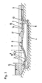
- the water sports device shown in FIGS. 1 to 3 in each case in longitudinal section has a water tank 1 as shown in DE-C-17 03 746 mentioned at the beginning.
- the water tank 1 which has an obliquely upwardly extending, in particular concavely curved bottom surface 2, adjoins a high tank 5 with a lower outlet extending over the entire width.
- the outlet of the elevated tank 1 forms the inflow nozzle 3, which is arranged at the lower edge of the bottom surface 2.
- the upper edge 8 of the bottom surface 2 forms an overflow 9 into an additional basin 7, the capacity of which corresponds at least to the filling volume of the tall container 5, but is preferably substantially larger.
- the end of the first area 10 is formed by a vertically arranged grille 14, on the downstream side of which a backflow flap 15 is arranged.
- the grid 14 divides the first area 10 from an area 11 further away from the overflow 9, in which the inlet 13 is arranged to a return line 4, which in this exemplary embodiment is formed by a closed pipeline running below the water tank 1, which runs from below into the outlet area of the tall container 5 opens.
- a circulation pump 6 is inserted into the return line 4. In the rest position shown in FIG.
- the backflow flap 15 receives the water in the area 11 at a higher level than in the area 10, from which it could partially flow back via the overflow 9 when the water tank 1 is emptied by pumping devices (not shown).
- the water tank 1 is delimited by walls 16 ′, which end approximately at the seat height above the water level of the shooting flow, in order to enable easy entry and exit into the water tank 1.
- An outer pair of side walls 16 ′′ delimits the water tank 1 and the additional pool 7 at a height above the level of the start shaft 17, the side walls 16 ′ being at least at the lowest point from the one above the floor surface 2 when the device is at a standstill before the high tank 5 is filled
- the additional pool 7 is of course provided with a transverse wall at the end, since the area 11 of the additional pool 7 and the elevated tank 5 communicate via the return line 4, the water level in the elevated tank 5 corresponds to that in the area 11 of the additional pool 7, ie the elevated tank 5 is only partially filled.
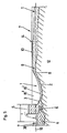
- the circulation pump 6 is initially activated, which comes from the area 11 of the additional pool 7 Sucks off water and fills the elevated tank 5, as shown in Fig.2. Initially, the inlet nozzle 3 remains closed until the required water level in the elevated tank 5 is reached.
- the area 11 of the additional basin still contains a sufficient water supply, from which water can be withdrawn at least as long as there is no large lowering of the mirror, until the water that shoots up over the bottom surface 2 re-enters the area 11 of the additional basin 7 from the inflow nozzle 3 that is now to be opened, so that the water cycle continues continuously.
- 3 shows the situation in which the start wave 17 formed by the flow start has reached the first area 10 of the additional basin 7, in which water is therefore still drawn from the area 11 without replenishment, the elevated tank 5 again partially emptied.
- the starting wave 17, which widens in the direction of flow, will subsequently reach the grating 14 and open the backflow flap 15, so that the water enters area 11, with which the water cycle can begin.
- the water tank 1 can be used to practice the sliding sports.
- the glider enters via one of the lower side walls 16 'on which he initially sits and can leave the water, container 1 again via the opposite lower side wall 16 ". If the athlete falls or his skill is still too low, he will over the Overflow 9 rinsed into the first area 10 of the additional basin 7, in which a noticeable there is a reduced flow velocity at a shallower water depth. He can therefore get out of the water sports device laterally in this area without disturbing the shooting flow in the water tank 1 and recover his sports equipment, which is caught on the grille 14. A practiced or lying surfer can also go out over the overflow 9 and get out in the same way.
- FIG. 1 A top view of a preferred embodiment is shown in FIG.
- the water tank 1 is here part of a leisure facility with a swimming channel 31, a children's pool 32, a non-swimmer pool 33 and a swirl pool 34.
- the elevated tank 5 is arranged on the left side of the water tank 1 in the drawing, whose outlet forms the inflow nozzle 3 to the rising bottom surface 2.
- the overflow 9 at the upper edge 8 of the rising floor surface 2 leads into the additional pool 7, which is divided by the grille 14 into the first area 10 adjoining the overflow 9, which is provided for the athletes' exit, and into the further area 11, from which the return line 4 starts.
- This is designed as an open channel and extends in any line around the water tank 1 again to the elevated tank 5 on the side opposite the feed line 3.
- the water circulation between the additional basin 7 and the inflow nozzle 3 necessary for the operation of the water sports device is utilized in various ways by the open channel. Cross-sectional changes in the swimming channel 31 thus result in different flow velocities, so that it is also possible to successfully swim against the current with, across and in places.
- the non-swimmer pool 33 and the start of the swimming channel 31 there is a partition 37 which can be flooded by the starting shaft 17, so that the starting shaft 17 is broken down and the starting process in the return channel is thus delayed.
- the adjoining walls of the swimming channel 31 can be kept lower.
- the swimming channel 31 can also be very long because it absorbs less water during the starting process.
- the water in the children's pool 32 is driven by an exchange of impulses from the swimming channel, with a separation 39 which prevents the exchange of energy as little as possible.
- the non-swimmer pool 33 is separated from the swirl pool 34 by a rope 40 carried by a float.
- the end section of the open channel is covered by an accessible cover 38 and separated from the vortex pool 34 by a slider 41.
- the circulating pump 6 is arranged in the transition between the end section of the return flow line and the elevated tank 5, the operation of the water sports device running as described above.
- the grid 14 in the additional basin 7 is again associated with the mentioned backflow flap 15, which prevents the backflow of water from the open channel into the emptied water tank 1. If the channel is long and resistant, the water level 19 can lie below the floor in the overflow 9 when the device is at rest (dash-dotted lines in FIG. 5), so that the arrangement of a backflow flap 15 can also be dispensed with.
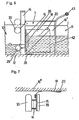
- the grille 14 with the backflow flap 15 is shown in detail in FIGS. 6 and 7, the situation corresponding to FIG. 2 being shown in the two areas 10, 11.
- the grid 14 consists of a number of vertical flat bars, on which a floating body 30 is loosely suspended, pointing towards the floor 11, which serves to protect the washed-up sports equipment.
- a hose 29 or the like is provided in the area of the grille 14 near the bottom.
- the cross-sectional shape as shown in dashed lines, can be changed by a pressure medium.
- the resistance of the grating 14 during operation of the device can be varied continuously, as a result of which the position of the transition stage from shooting into normal flow in the first region 10 of the additional basin 7 can also be changed.
- the backflow flap 15 is movably connected to the bottom and a seal 18 to the side wall 16 by means of a waterproof hinge 28, both the hinge 28 and the seal 18 each consisting of flexible film.
- the side seal 18 is fixed by means of a bar 20 "attached obliquely to the side wall 16", so that the backflow flap 15 folds down into the dash-dot position when the flow starts, and is pushed up again by a buoyancy body 39 when the water container 1 is emptied Access barrier referred to, which consists for example of individual vertical bars to which a cross bar 43 is attached as a handle.
- Backflow flaps 26 are connected to the grid 24 of the first additional basin 7 and are opened when the flow starts and are closed again by the water pumped back into the second elevated tank 25 when the second water tank 21 is emptied.
- the circulation pump 6 is arranged at the foot of the first elevated tank 5, and a connecting line 27 provided by a flap 44 is formed between the two elevated tanks 5, 25.
- both high tanks 5 and 25 are filled to the same height with water. Then the flap 44 is closed and the inflow nozzles 3 and 23 are opened in such a chronological order that when the start wave arrives from the water tank 1 the level in the elevated tank 25 is just below that of the start wave, as a result of which the backflow flaps 26 open.
- the water sports device allows the problem-free installation of gearless submersible pumps 6, which are preferably produced in series, and the simultaneous practice of various water sports by numerous people.
Landscapes
- Farming Of Fish And Shellfish (AREA)
- Special Spraying Apparatus (AREA)
- Massaging Devices (AREA)
- Structures Of Non-Positive Displacement Pumps (AREA)
Claims (8)
Priority Applications (5)
| Application Number | Priority Date | Filing Date | Title |
|---|---|---|---|
| DE8484114072T DE3466353D1 (en) | 1984-11-22 | 1984-11-22 | Appliance for practising aquatic sports |
| AT84114072T ATE29842T1 (de) | 1984-11-22 | 1984-11-22 | Wassersporteinrichtung. |
| EP84114072A EP0182923B1 (fr) | 1984-11-22 | 1984-11-22 | Appareil pour l'exercice de sports nautiques |
| US07/265,318 US4905987A (en) | 1984-11-22 | 1988-10-27 | Water sports apparatus |
| US07/843,950 USRE34407E (en) | 1984-11-22 | 1992-02-21 | Water sports apparatus |
Applications Claiming Priority (1)
| Application Number | Priority Date | Filing Date | Title |
|---|---|---|---|
| EP84114072A EP0182923B1 (fr) | 1984-11-22 | 1984-11-22 | Appareil pour l'exercice de sports nautiques |
Publications (2)
| Publication Number | Publication Date |
|---|---|
| EP0182923A1 EP0182923A1 (fr) | 1986-06-04 |
| EP0182923B1 true EP0182923B1 (fr) | 1987-09-23 |
Family
ID=8192296
Family Applications (1)
| Application Number | Title | Priority Date | Filing Date |
|---|---|---|---|
| EP84114072A Expired EP0182923B1 (fr) | 1984-11-22 | 1984-11-22 | Appareil pour l'exercice de sports nautiques |
Country Status (4)
| Country | Link |
|---|---|
| US (1) | US4905987A (fr) |
| EP (1) | EP0182923B1 (fr) |
| AT (1) | ATE29842T1 (fr) |
| DE (1) | DE3466353D1 (fr) |
Families Citing this family (68)
| Publication number | Priority date | Publication date | Assignee | Title |
|---|---|---|---|---|
| US5236280A (en) * | 1987-05-27 | 1993-08-17 | Blade Loch, Inc. | Method and apparatus for improving sheet flow water rides |
| US5171101A (en) * | 1987-05-27 | 1992-12-15 | Light Wave, Ltd. | Surfing-wave generators |
| US5401117A (en) * | 1987-05-27 | 1995-03-28 | Lochtefeld; Thomas J. | Method and apparatus for containerless sheet flow water rides |
| US5271692A (en) * | 1987-05-27 | 1993-12-21 | Light Wave, Ltd. | Method and apparatus for a sheet flow water ride in a single container |
| US5667445A (en) * | 1988-12-19 | 1997-09-16 | Light Wave Ltd. | Jet river rapids water attraction |
| US5421782A (en) * | 1990-08-15 | 1995-06-06 | Light Wave, Inc. | Action river water attraction |
| US5213547A (en) * | 1990-08-15 | 1993-05-25 | Light Wave, Ltd. | Method and apparatus for improved water rides by water injection and flume design |
| AU8520791A (en) * | 1990-09-04 | 1992-03-30 | Thomas J. Lochtefeld | Water ride attraction |
| FR2671977A1 (fr) * | 1991-01-24 | 1992-07-31 | Int Indoor Productions | Installation pour la pratique des sports de glisse sur eau du type planche a voile. |
| US5766082A (en) * | 1993-05-20 | 1998-06-16 | Lochtefeld; Thomas J. | Wave river water attraction |
| US5503597A (en) * | 1994-03-09 | 1996-04-02 | Lochtefeld; Thomas J. | Method and apparatus for injected water corridor attractions |
| US5637025A (en) * | 1995-12-12 | 1997-06-10 | Aquaplay Ab | Gate and harbor for water activity toy |
| US5899634A (en) * | 1996-10-22 | 1999-05-04 | Light Wave, Ltd. | Simulated wave water sculpture |
| US6161771A (en) * | 1997-05-23 | 2000-12-19 | Water Ride Concepts, Inc. | Water fountain system and method |
| US6758231B1 (en) * | 1998-06-17 | 2004-07-06 | Light Wave Ltd. | Redundant array control system for water rides |
| US6261186B1 (en) | 1998-07-24 | 2001-07-17 | Nbgs International, Inc. | Water amusement system and method |
| US6036603A (en) * | 1998-09-29 | 2000-03-14 | Universal Studios, Inc. | Whirlpool simulation effect |
| US6491589B1 (en) | 1999-08-02 | 2002-12-10 | Light Wave, Ltd. | Mobile water ride having sluice slide-over cover |
| US6454659B1 (en) | 2000-06-14 | 2002-09-24 | Forrest Noble | Kayaking simulation device for creating a recirculating hydraulic hole effect within a receiving pool |
| US6702687B1 (en) | 2000-06-23 | 2004-03-09 | Nbgs International, Inc. | Controller system for water amusement devices |
| AU2001290832B2 (en) | 2000-09-11 | 2007-08-02 | Water Ride Concepts, Inc. | Water amusement system and method |
| WO2002039862A1 (fr) | 2000-11-16 | 2002-05-23 | Lochtefeld Thomas J | Procede et appareil pour piscine a vagues |
| US7179173B2 (en) * | 2002-03-25 | 2007-02-20 | Nbgs International Inc. | Control system for water amusement devices |
| US6920651B2 (en) * | 2003-06-05 | 2005-07-26 | Michael Kevin Roberts | Surfing ring wave pool for generating multiple simultaneous endless traveling waves looping around a center island |
| US7229359B2 (en) | 2003-10-24 | 2007-06-12 | Henry, Schooley & Associates, L.L.C. | Continuous water ride |
| US20050114706A1 (en) * | 2003-11-26 | 2005-05-26 | Destefano Jason Michael | System and method for the collection and transmission of log data over a wide area network |
| US7497784B2 (en) * | 2004-11-24 | 2009-03-03 | Water Ride Concepts, Inc. | Rollable carrier ride |
| US7597630B2 (en) * | 2004-11-24 | 2009-10-06 | Water Ride Concepts, Inc. | Water amusement park conveyors |
| CA2611139A1 (fr) * | 2005-04-20 | 2006-10-26 | Henry, Schooley & Associates, L.L.C. | Systeme d'attraction aquatique comportant des arbres composites |
| US7775895B2 (en) * | 2005-08-03 | 2010-08-17 | Water Ride Concepts, Inc. | Water amusement park water channel and adjustable flow controller |
| US7727077B2 (en) * | 2005-08-03 | 2010-06-01 | Water Ride Concepts, Inc. | Water amusement park water channel flow system |
| US7371183B2 (en) * | 2005-08-30 | 2008-05-13 | Henry, Schooley & Associates, L.L.C. | Water amusement park conveyors |
| US7815514B2 (en) * | 2005-08-30 | 2010-10-19 | Water Ride Concepts, Inc. | Water amusement park conveyor barriers |
| US7762899B2 (en) | 2005-08-30 | 2010-07-27 | Water Ride Concepts, Inc. | Water amusement park conveyor support elements |
| US8282497B2 (en) * | 2005-08-30 | 2012-10-09 | Water Ride Concepts, Inc. | Modular water amusement park conveyors |
| US20070049386A1 (en) * | 2005-08-30 | 2007-03-01 | Henry Jeffery W | Adjusting participant flow rate in water amusement parks |
| US7828667B2 (en) * | 2005-09-02 | 2010-11-09 | Water Ride Concepts, Inc. | Methods and systems for active filtration of portions of self-contained floating marine parks |
| US7758435B2 (en) | 2005-09-02 | 2010-07-20 | Water Ride Concepts, Inc. | Amusement water rides involving interactive user environments |
| US8210954B2 (en) | 2005-09-02 | 2012-07-03 | Water Ride Concepts, Inc. | Amusement water rides involving exercise circuits |
| WO2007035524A2 (fr) | 2005-09-15 | 2007-03-29 | Water Ride Concepts Inc. | Tours aquatiques de divertissement faisant intervenir des jeux de hasard |
| US7762900B2 (en) | 2006-03-14 | 2010-07-27 | Water Ride Concepts, Inc. | Method and system of positionable covers for water amusement parks |
| FR2906287B1 (fr) * | 2006-09-26 | 2012-08-10 | Hydrostadium | Installation pour la pratique d'activites aquatiques |
| US9103133B2 (en) * | 2012-11-01 | 2015-08-11 | American Wave Machines, Inc. | Sequenced chamber wave generator controller and method |
| US20080286048A1 (en) * | 2007-03-09 | 2008-11-20 | Brandon Carnahan | Sheet flow water ride apparatus and method |
| US20080286047A1 (en) * | 2007-03-09 | 2008-11-20 | Brandon Carnahan | River water ride apparatus and method |
| WO2008112123A2 (fr) * | 2007-03-09 | 2008-09-18 | Waveyard Development, Llc | Système de vague statique pour la formation de vagues |
| WO2009064445A1 (fr) * | 2007-11-13 | 2009-05-22 | Lochtefeld Thomas J | Procédé et appareil pouvant varier le débit d'eau d'un parcours de surf aquatique à écoulement en nappe stationnaire |
| US9856665B2 (en) | 2008-11-25 | 2018-01-02 | Thomas J. Lochtefeld | Method and apparatus for dampening waves in a wave pool |
| US9506259B2 (en) | 2008-11-25 | 2016-11-29 | Thomas J. Lochtefeld | Method and apparatus for dampening waves in a wave pool |
| PT2369968T (pt) * | 2008-11-25 | 2020-09-24 | Hendrik Dirk Van Ettinger | Método e aparelho para amortecimento de ondas numa piscina de ondas |
| US9879438B2 (en) | 2008-11-25 | 2018-01-30 | Thomas J. Lochtefeld | Method and apparatus for dampening waves in a wave pool using padded grate drainage system |
| US9550127B2 (en) | 2013-03-21 | 2017-01-24 | Thomas J. Lochtefeld | Padded grate drainage system for water rides |
| US8079916B2 (en) | 2008-12-18 | 2011-12-20 | Water Ride Concepts, Inc. | Themed amusement river ride system |
| CA2989461C (fr) | 2013-10-30 | 2020-03-10 | Oriol A. Vicente | Appareil de surf gonflable et procede connexe |
| US10458136B2 (en) | 2014-08-25 | 2019-10-29 | Thomas J. Lochtefeld | Method and apparatus for producing waves suitable for surfing using wave-forming caissons with floating wave attenuator |
| US9511297B2 (en) * | 2015-04-07 | 2016-12-06 | Universal City Studios Llc | Slide entry system |
| CA3221253A1 (fr) | 2015-11-12 | 2017-05-12 | Whitewater West Industries Ltd. | Methode et appareil de fixation de surfaces de manege gonflable |
| CA2948584C (fr) | 2015-11-12 | 2025-10-07 | Whitewater West Industries Ltd. | Appareillage de surf gonflable transportable et methode |
| CA2948581C (fr) | 2015-11-13 | 2024-01-16 | Whitewater West Industries Ltd. | Appareil de glisse sur l'eau gonflable et methode permettant de reduire la turbulence du liquide |
| WO2017218902A1 (fr) * | 2016-06-17 | 2017-12-21 | Davis Allen Tanner | Système et procédé de génération de vagues |
| WO2018083265A1 (fr) * | 2016-11-04 | 2018-05-11 | Lengermann + Trieschmann Gmbh + Co. Kg | Système pour la production d'une vague artificielle |
| JP7083520B2 (ja) | 2016-11-08 | 2022-06-13 | カアナ ウェーブ カンパニー インコーポレイテッド | 造波方法および装置 |
| US10119285B2 (en) | 2017-01-20 | 2018-11-06 | The Wave Pool Company, LLC | Systems and methods for generating waves |
| US11273383B2 (en) | 2017-11-10 | 2022-03-15 | Whitewater West Industries Ltd. | Water ride attraction incorporating a standing wave |
| AT523412B1 (de) * | 2020-01-24 | 2021-08-15 | Gmeiner Tobias | Vorrichtung und Verfahren zum Erzeugen einer künstlichen Surfwelle |
| US12404688B2 (en) * | 2020-05-18 | 2025-09-02 | Whitewater West Industries Ltd. | Return channel for a surf pool |
| EP4153827A4 (fr) * | 2020-05-18 | 2024-07-17 | Whitewater West Industries Ltd | Générateur à vagues sur piscine |
| EP4200041B1 (fr) * | 2021-07-05 | 2024-02-14 | Thilo Trefz | Unité de pompe pour équipement de surf mobile avec une pompe centrifuge et un diffuseur |
Family Cites Families (17)
| Publication number | Priority date | Publication date | Assignee | Title |
|---|---|---|---|---|
| DE159793C (fr) * | ||||
| US490484A (en) * | 1893-01-24 | Steele mackaye | ||
| US1536875A (en) * | 1924-07-03 | 1925-05-05 | Edgar W Bowen | Swimming pool |
| GB375684A (en) * | 1930-12-02 | 1932-06-30 | Bamag Meguin Ag | Production of artificial waves in swimming pools and the like |
| US1884075A (en) * | 1931-06-15 | 1932-10-25 | Ericsson H Merritt | Consistency responsive device |
| FR761489A (fr) * | 1933-09-19 | 1934-03-20 | Attraction foraine | |
| US2815951A (en) * | 1956-01-19 | 1957-12-10 | Nicholas T Baldanza | Water skiing training device |
| US3038760A (en) * | 1959-11-06 | 1962-06-12 | Donald W Crooke | Fish ladder |
| GB935054A (en) * | 1962-04-27 | 1963-08-28 | Flygts Pumpar Ab | Apparatus for studying of swimmers |
| GB1090262A (en) * | 1964-02-04 | 1967-11-08 | Frederick Hugh Percy Buckner | Improvements in and relating to apparatus for amusements and instructional purposes |
| GB1118083A (en) * | 1965-03-30 | 1968-06-26 | Gerald Douglas Marvin | Ski training and practising apparatus |
| GB1159269A (en) * | 1966-12-02 | 1969-07-23 | Richard Bobart Buswell | Apparatus for producing a Moving Fluid Surface |
| FR1539959A (fr) * | 1967-08-11 | 1968-09-20 | Appareil de sport nautique | |
| US3473334A (en) * | 1968-06-24 | 1969-10-21 | Phillip Dexter | Apparatus and method for producing waves |
| DE2222594A1 (de) * | 1972-05-09 | 1973-11-29 | Karl Guenter Hoppe | Schwimmbecken mit umlaufstroemung |
| US3913332A (en) * | 1973-08-30 | 1975-10-21 | Arnold H Forsman | Continuous wave surfing facility |
| AT379513B (de) * | 1982-06-07 | 1986-01-27 | Frenzl Otto | Wassersporteinrichtung |
-
1984
- 1984-11-22 EP EP84114072A patent/EP0182923B1/fr not_active Expired
- 1984-11-22 AT AT84114072T patent/ATE29842T1/de not_active IP Right Cessation
- 1984-11-22 DE DE8484114072T patent/DE3466353D1/de not_active Expired
-
1988
- 1988-10-27 US US07/265,318 patent/US4905987A/en not_active Ceased
Also Published As
| Publication number | Publication date |
|---|---|
| US4905987A (en) | 1990-03-06 |
| DE3466353D1 (en) | 1987-10-29 |
| EP0182923A1 (fr) | 1986-06-04 |
| ATE29842T1 (de) | 1987-10-15 |
Similar Documents
| Publication | Publication Date | Title |
|---|---|---|
| EP0182923B1 (fr) | Appareil pour l'exercice de sports nautiques | |
| EP0096216B1 (fr) | Procédé pour la pratique de sport nautique, dans lequel de l'eau est dirigée vers le haut sur une surface inclinée, et installation pour la mise en oeuvre du procédé | |
| DE60027172T2 (de) | Mobile wellenreitattraktion mit einer aufschiebbaren abdeckung für eine schleuse | |
| DE19917507C2 (de) | Schwimmbecken mit Gegenstrom-Schwimmanlage | |
| DE1808906A1 (de) | Vorrichtung zur Erzeugung von Wellen zum Wellenreiten | |
| DE1684877B2 (de) | Vorrichtung zur Erzeugung einer Wasserbewegung in einem Schwimmbecken oder einer anderen Wasseransammlung | |
| DE2222594A1 (de) | Schwimmbecken mit umlaufstroemung | |
| DE2130967C3 (de) | Vorrichtung zum Trennen zweier in einer heterogenen Flüssigkeit enthaltender Flüssigkeitsbestandteile | |
| DE102008057785A1 (de) | Künstliche Surfanlage | |
| DE2534242A1 (de) | Wasserrutschbahn wowie verfahren zum anlegen und betreiben derselben | |
| DE3441491A1 (de) | Verfahren und vorrichtung zur oelkonzentration | |
| EP0429593A1 (fr) | Separateur de liquides legers. | |
| EP4066911A1 (fr) | Procédé de commande d'un sens de toboggan dans un appareil de voie, ainsi que appareil de voie pour un toboggan aquatique | |
| DE69122400T2 (de) | Wasserrutschbahn mit wassertreibstrahlvorrichtungen | |
| EP2788563B1 (fr) | Dispositif et procédé pour produire un profil de vague dans l'eau | |
| DE60036947T2 (de) | Vorrichtung und verfahren zum erzeugen von wellen | |
| DE3403718A1 (de) | Leichtfluessigkeitsabscheider | |
| DE2822877C2 (de) | Hebevorrichtung für mit Dickstoffen versetzte Abwässer o.dgl. | |
| DE3812435C1 (en) | Chute installation | |
| DE1964208A1 (de) | Verfahren und Vorrichtung zur Rueckgewinnung eines Stoffes,der Form einer duennen Schicht auf der Oberflaeche einer fluessigen Mas schwimmt | |
| AT522329A4 (de) | Vorrichtung zur selbsttätigen Wasserstandsregulierung für ein Wasserreservoir | |
| DE3447161A1 (de) | Wirbelduesenbecken | |
| DE19711558A1 (de) | Wasserrutsche | |
| DE29724379U1 (de) | Wasserrutsche | |
| DE3518951A1 (de) | Speicher- u. spuelvorrichtung fuer ein zeitweise gefuelltes becken insbesondere fuer ein regenbecken |
Legal Events
| Date | Code | Title | Description |
|---|---|---|---|
| PUAI | Public reference made under article 153(3) epc to a published international application that has entered the european phase |
Free format text: ORIGINAL CODE: 0009012 |
|
| 17P | Request for examination filed |
Effective date: 19860205 |
|
| AK | Designated contracting states |
Kind code of ref document: A1 Designated state(s): AT BE CH DE FR GB IT LI NL SE |
|
| 17Q | First examination report despatched |
Effective date: 19870319 |
|
| GRAA | (expected) grant |
Free format text: ORIGINAL CODE: 0009210 |
|
| AK | Designated contracting states |
Kind code of ref document: B1 Designated state(s): AT BE CH DE FR GB IT LI NL SE |
|
| REF | Corresponds to: |
Ref document number: 29842 Country of ref document: AT Date of ref document: 19871015 Kind code of ref document: T |
|
| PG25 | Lapsed in a contracting state [announced via postgrant information from national office to epo] |
Ref country code: SE Effective date: 19870930 |
|
| REF | Corresponds to: |
Ref document number: 3466353 Country of ref document: DE Date of ref document: 19871029 |
|
| ITF | It: translation for a ep patent filed | ||
| ET | Fr: translation filed | ||
| GBT | Gb: translation of ep patent filed (gb section 77(6)(a)/1977) | ||
| PLBE | No opposition filed within time limit |
Free format text: ORIGINAL CODE: 0009261 |
|
| STAA | Information on the status of an ep patent application or granted ep patent |
Free format text: STATUS: NO OPPOSITION FILED WITHIN TIME LIMIT |
|
| 26N | No opposition filed | ||
| ITTA | It: last paid annual fee | ||
| REG | Reference to a national code |
Ref country code: GB Ref legal event code: 746 |
|
| ITPR | It: changes in ownership of a european patent |
Owner name: OFFERTA DI LICENZA AL PUBBLICO |
|
| REG | Reference to a national code |
Ref country code: FR Ref legal event code: DL |
|
| NLS | Nl: assignments of ep-patents |
Owner name: LOTEC B.V. TE EINDHOVEN. |
|
| REG | Reference to a national code |
Ref country code: CH Ref legal event code: PUE Owner name: LOTEC B.V. |
|
| REG | Reference to a national code |
Ref country code: GB Ref legal event code: 732E |
|
| ITPR | It: changes in ownership of a european patent |
Owner name: CESSIONE;LOTEC B.V. |
|
| REG | Reference to a national code |
Ref country code: FR Ref legal event code: TP |
|
| PGFP | Annual fee paid to national office [announced via postgrant information from national office to epo] |
Ref country code: NL Payment date: 20000524 Year of fee payment: 16 |
|
| PGFP | Annual fee paid to national office [announced via postgrant information from national office to epo] |
Ref country code: FR Payment date: 20000526 Year of fee payment: 16 |
|
| PGFP | Annual fee paid to national office [announced via postgrant information from national office to epo] |
Ref country code: AT Payment date: 20000531 Year of fee payment: 16 |
|
| PGFP | Annual fee paid to national office [announced via postgrant information from national office to epo] |
Ref country code: BE Payment date: 20000609 Year of fee payment: 16 |
|
| PG25 | Lapsed in a contracting state [announced via postgrant information from national office to epo] |
Ref country code: AT Free format text: LAPSE BECAUSE OF NON-PAYMENT OF DUE FEES Effective date: 20001122 |
|
| PG25 | Lapsed in a contracting state [announced via postgrant information from national office to epo] |
Ref country code: BE Free format text: LAPSE BECAUSE OF NON-PAYMENT OF DUE FEES Effective date: 20001130 |
|
| PGFP | Annual fee paid to national office [announced via postgrant information from national office to epo] |
Ref country code: GB Payment date: 20010522 Year of fee payment: 17 |
|
| PGFP | Annual fee paid to national office [announced via postgrant information from national office to epo] |
Ref country code: CH Payment date: 20010528 Year of fee payment: 17 |
|
| BERE | Be: lapsed |
Owner name: LOTEC B.V. Effective date: 20001130 |
|
| PG25 | Lapsed in a contracting state [announced via postgrant information from national office to epo] |
Ref country code: NL Free format text: LAPSE BECAUSE OF NON-PAYMENT OF DUE FEES Effective date: 20010601 |
|
| PGFP | Annual fee paid to national office [announced via postgrant information from national office to epo] |
Ref country code: DE Payment date: 20010725 Year of fee payment: 17 |
|
| PG25 | Lapsed in a contracting state [announced via postgrant information from national office to epo] |
Ref country code: FR Free format text: LAPSE BECAUSE OF NON-PAYMENT OF DUE FEES Effective date: 20010731 |
|
| NLV4 | Nl: lapsed or anulled due to non-payment of the annual fee |
Effective date: 20010601 |
|
| REG | Reference to a national code |
Ref country code: FR Ref legal event code: ST |
|
| PG25 | Lapsed in a contracting state [announced via postgrant information from national office to epo] |
Ref country code: GB Free format text: LAPSE BECAUSE OF NON-PAYMENT OF DUE FEES Effective date: 20011122 |
|
| PG25 | Lapsed in a contracting state [announced via postgrant information from national office to epo] |
Ref country code: LI Free format text: LAPSE BECAUSE OF NON-PAYMENT OF DUE FEES Effective date: 20011130 Ref country code: CH Free format text: LAPSE BECAUSE OF NON-PAYMENT OF DUE FEES Effective date: 20011130 |
|
| REG | Reference to a national code |
Ref country code: GB Ref legal event code: IF02 |
|
| PG25 | Lapsed in a contracting state [announced via postgrant information from national office to epo] |
Ref country code: DE Free format text: LAPSE BECAUSE OF NON-PAYMENT OF DUE FEES Effective date: 20020702 |
|
| GBPC | Gb: european patent ceased through non-payment of renewal fee |
Effective date: 20011122 |
|
| REG | Reference to a national code |
Ref country code: CH Ref legal event code: PL |