EP0182926B1 - Incubateur autonome - Google Patents
Incubateur autonome Download PDFInfo
- Publication number
- EP0182926B1 EP0182926B1 EP19840114136 EP84114136A EP0182926B1 EP 0182926 B1 EP0182926 B1 EP 0182926B1 EP 19840114136 EP19840114136 EP 19840114136 EP 84114136 A EP84114136 A EP 84114136A EP 0182926 B1 EP0182926 B1 EP 0182926B1
- Authority
- EP
- European Patent Office
- Prior art keywords
- culture growth
- medium
- seeded
- receiving
- bacteria
- Prior art date
- Legal status (The legal status is an assumption and is not a legal conclusion. Google has not performed a legal analysis and makes no representation as to the accuracy of the status listed.)
- Expired
Links
- 238000011534 incubation Methods 0.000 title claims description 40
- 230000012010 growth Effects 0.000 claims description 43
- 241000894006 Bacteria Species 0.000 claims description 42
- 239000001963 growth medium Substances 0.000 claims description 36
- 230000003287 optical effect Effects 0.000 claims description 32
- 238000010438 heat treatment Methods 0.000 claims description 20
- 241000192125 Firmicutes Species 0.000 claims description 19
- 244000005700 microbiome Species 0.000 claims description 17
- 239000002609 medium Substances 0.000 claims description 14
- 239000012530 fluid Substances 0.000 claims description 7
- 238000004891 communication Methods 0.000 claims description 3
- 238000000338 in vitro Methods 0.000 claims description 3
- 239000000463 material Substances 0.000 claims description 3
- 239000013589 supplement Substances 0.000 claims description 3
- 230000000007 visual effect Effects 0.000 claims description 3
- 230000009469 supplementation Effects 0.000 claims 1
- 210000004027 cell Anatomy 0.000 description 44
- 208000015181 infectious disease Diseases 0.000 description 12
- 238000009630 liquid culture Methods 0.000 description 10
- 238000000034 method Methods 0.000 description 9
- 239000007787 solid Substances 0.000 description 9
- 208000019206 urinary tract infection Diseases 0.000 description 9
- 230000001580 bacterial effect Effects 0.000 description 7
- 238000005259 measurement Methods 0.000 description 7
- 239000000758 substrate Substances 0.000 description 7
- 210000002700 urine Anatomy 0.000 description 6
- 238000013022 venting Methods 0.000 description 6
- 239000012212 insulator Substances 0.000 description 5
- 238000001514 detection method Methods 0.000 description 4
- 230000000763 evoking effect Effects 0.000 description 4
- 230000001965 increasing effect Effects 0.000 description 4
- 230000001788 irregular Effects 0.000 description 4
- 230000000813 microbial effect Effects 0.000 description 4
- 230000002906 microbiologic effect Effects 0.000 description 4
- 239000006916 nutrient agar Substances 0.000 description 3
- 230000035755 proliferation Effects 0.000 description 3
- 210000001635 urinary tract Anatomy 0.000 description 3
- 229920001817 Agar Polymers 0.000 description 2
- 208000035143 Bacterial infection Diseases 0.000 description 2
- PXIPVTKHYLBLMZ-UHFFFAOYSA-N Sodium azide Chemical compound [Na+].[N-]=[N+]=[N-] PXIPVTKHYLBLMZ-UHFFFAOYSA-N 0.000 description 2
- 239000008272 agar Substances 0.000 description 2
- 238000000149 argon plasma sintering Methods 0.000 description 2
- 208000022362 bacterial infectious disease Diseases 0.000 description 2
- 230000005757 colony formation Effects 0.000 description 2
- 230000000295 complement effect Effects 0.000 description 2
- 239000004020 conductor Substances 0.000 description 2
- 230000009977 dual effect Effects 0.000 description 2
- 238000005286 illumination Methods 0.000 description 2
- 239000011810 insulating material Substances 0.000 description 2
- 238000009413 insulation Methods 0.000 description 2
- 238000004519 manufacturing process Methods 0.000 description 2
- 230000005499 meniscus Effects 0.000 description 2
- 229910052751 metal Inorganic materials 0.000 description 2
- 239000002184 metal Substances 0.000 description 2
- 239000004033 plastic Substances 0.000 description 2
- 229920003023 plastic Polymers 0.000 description 2
- 238000007789 sealing Methods 0.000 description 2
- 208000003322 Coinfection Diseases 0.000 description 1
- 229920000877 Melamine resin Polymers 0.000 description 1
- 229910000831 Steel Inorganic materials 0.000 description 1
- 239000000853 adhesive Substances 0.000 description 1
- 230000001070 adhesive effect Effects 0.000 description 1
- 229910052782 aluminium Inorganic materials 0.000 description 1
- XAGFODPZIPBFFR-UHFFFAOYSA-N aluminium Chemical compound [Al] XAGFODPZIPBFFR-UHFFFAOYSA-N 0.000 description 1
- 239000003242 anti bacterial agent Substances 0.000 description 1
- 229940088710 antibiotic agent Drugs 0.000 description 1
- 239000000919 ceramic Substances 0.000 description 1
- 239000011248 coating agent Substances 0.000 description 1
- 238000000576 coating method Methods 0.000 description 1
- 238000011161 development Methods 0.000 description 1
- 238000010586 diagram Methods 0.000 description 1
- 239000011152 fibreglass Substances 0.000 description 1
- 230000008014 freezing Effects 0.000 description 1
- 238000007710 freezing Methods 0.000 description 1
- 210000005255 gram-positive cell Anatomy 0.000 description 1
- 238000011065 in-situ storage Methods 0.000 description 1
- 239000003112 inhibitor Substances 0.000 description 1
- 230000000977 initiatory effect Effects 0.000 description 1
- 239000007788 liquid Substances 0.000 description 1
- 238000012423 maintenance Methods 0.000 description 1
- JDSHMPZPIAZGSV-UHFFFAOYSA-N melamine Chemical compound NC1=NC(N)=NC(N)=N1 JDSHMPZPIAZGSV-UHFFFAOYSA-N 0.000 description 1
- 244000000010 microbial pathogen Species 0.000 description 1
- 238000012544 monitoring process Methods 0.000 description 1
- 235000015097 nutrients Nutrition 0.000 description 1
- 238000005375 photometry Methods 0.000 description 1
- 229920002635 polyurethane Polymers 0.000 description 1
- 239000004814 polyurethane Substances 0.000 description 1
- 239000000843 powder Substances 0.000 description 1
- 239000004065 semiconductor Substances 0.000 description 1
- 239000010959 steel Substances 0.000 description 1
- 238000004381 surface treatment Methods 0.000 description 1
- 238000012360 testing method Methods 0.000 description 1
- 239000012815 thermoplastic material Substances 0.000 description 1
- 238000012546 transfer Methods 0.000 description 1
- 239000012780 transparent material Substances 0.000 description 1
Images


Classifications
-
- C—CHEMISTRY; METALLURGY
- C12—BIOCHEMISTRY; BEER; SPIRITS; WINE; VINEGAR; MICROBIOLOGY; ENZYMOLOGY; MUTATION OR GENETIC ENGINEERING
- C12M—APPARATUS FOR ENZYMOLOGY OR MICROBIOLOGY; APPARATUS FOR CULTURING MICROORGANISMS FOR PRODUCING BIOMASS, FOR GROWING CELLS OR FOR OBTAINING FERMENTATION OR METABOLIC PRODUCTS, i.e. BIOREACTORS OR FERMENTERS
- C12M23/00—Constructional details, e.g. recesses, hinges
- C12M23/42—Integrated assemblies, e.g. cassettes or cartridges
-
- C—CHEMISTRY; METALLURGY
- C12—BIOCHEMISTRY; BEER; SPIRITS; WINE; VINEGAR; MICROBIOLOGY; ENZYMOLOGY; MUTATION OR GENETIC ENGINEERING
- C12M—APPARATUS FOR ENZYMOLOGY OR MICROBIOLOGY; APPARATUS FOR CULTURING MICROORGANISMS FOR PRODUCING BIOMASS, FOR GROWING CELLS OR FOR OBTAINING FERMENTATION OR METABOLIC PRODUCTS, i.e. BIOREACTORS OR FERMENTERS
- C12M41/00—Means for regulation, monitoring, measurement or control, e.g. flow regulation
- C12M41/12—Means for regulation, monitoring, measurement or control, e.g. flow regulation of temperature
Definitions
- This invention relates generally to the field of microbiology, and more particularly, to a self-sufficient incubation assembly for the in situ or in vitro culture of microorganisms such as bacteria.
- Another object of the present invention is to provide a novel self-sufficient incubation assembly including nutrient media, heating element and energy sources, etc. for instantaneously initiating and continuing microbiological procedures.
- a still further object of the present invention is to provide a novel self-sufficient incubation assembly having an optical assembly to visually magnify the culture growth and thus enhance observation of the microbial colonies.
- Still another object of the present invention is to provide a novel disposable self-sufficient incubation assembly.
- Yet another object of the present invention is to provide a novel self-sufficient incubation assembly which is relatively small and inexpensively produced.
- a novel self-sufficient incubation assembly comprised of a base member formed of suitable insulating material and a cover member therefor wherein the base member is formed with a chamber in which is positioned a culture growth dish assembly including a heating element readily connectable to a source of electric energy and wherein nutrient agar cells may be or are readily positioned on the culture growth dish assembly.
- the self-sufficient incubation assembly is provided with an optical assembly including a positive magnification lens system to permit observation of the microbial colonies, in enlarged view.
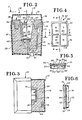
- FIG. 1 there is illustrated a generally square-shaped incubation assembly of the present invention generally indicated as 10, comprised of base member 12, an inner cover member 14, and a top closure member 16.
- the base member 12 of the incubation assembly 10 is comprised of a substantially solid body 18 formed of an insulating material, such as closed celled polyurethane, positioned within a hollow container 20 formed of a rigid thermoplastic material to provide structural integrity to the incubation assembly 10.
- the inner surface of the hollow container 20 may be formed with a vacuum metal-plated surface for heat transfer considerations.
- the solid body 18, Figure 2 is formed with a generally U-shaped (in cross-section) channel 22 circumferentially disposed within a top surface 24 of the solid body 18 to cooperate with the inner cover member 14, as hereinafter more fully disclosed.
- a centrally disposed, substantially rectangularly shaped inner chamber 26 defined by downwardly and inwardly inclined inner side walls 28 and 30 terminating by a bottom wall 32.
- a vertically disposed channel 34 forming with the inner surface of the hollow container 20 a housing chamber for a battery generally indicated at 36, such as the planar-type battery manufactured by the Polaroid Corporation.
- a horizontally disposed channel 38 for positioning a switch assembly 40 with access thereto being provided by an opening 42 in the bottom of the hollow container 20.
- the switch 40 is connected by conductors 44 to the battery 36.
- a channel 46 is provided between chamber 26 and channel 38 for conductors 48.
- the generally square shaped inner cover member 14, Figure 2 is provided with a rectangularly shaped opening formed by downwardly and inwardly sloping walls 50 and 52, the lower portions of which cooperate with the top portion of the side walls 28 and 30, respectively, defining the chamber 26.
- the inner cover member 14 is formed with a downwardly extending, circumferentially disposed U-shaped (in cross section) portion 54 cooperating with the U-shaped channel 22 of the solid body 18 to provide for structural integrity and to enhance thermal properties.
- the top closure member 16 is formed of a top wall 56 and downwardly depending side walls 58, the ends of which cooperate with the top of the hollow container 20.
- a rectangularly shaped culture growth dish assembly generally indicated as 60 (referring now to Figures 4 to 6) comprised of thermally conductive plate member 62 formed of a biologically inert coated substrate, such as aluminum or steel, positioned within a plastic frame member 64.
- the thermally conductive plate member 62 ( Figure 5) having a top surface 66 and a bottom surface 68 is provided on the bottom surface 68 thereof with heating elements 70 connected to circuitry, generally indicated as 72, comprised of transistors and a thermistor for controlling the temperature to which the heating elements 70 are raised and for maintaining the heating elements 70 at a temperature to provide a physiological temperature range of between about 35.8 to about 36.2°C.
- the frame member 64 ( Figure 4) is formed of downwardly and inwardly inclined side walls 74 and end walls 76 including cross members 78 and 80 disposed perpendicularly to one another and intermediate the side walls 74 and end walls 76, respectively, forming cells I to IV with the plate member 62. Beneath a plane formed by the lower portion of the cross member 78 and 80, there is formed a groove 82 ( Figures 5 and 6) in one end wall 76, a groove 84 in each side wall 74 and a slot 86 in the other end wall 76 for positioning of said plate member within the frame member 64, the slot 86 being dimensioned to permit passage of circuitry 72.
- the incubation assembly 10 of the present invention is provided with nutrient agar cells 88 (one shown) to permit instantaneous use of the incubation assembly 10.
- an optical assembly for positive magnification comprised of an upper lens 92 and a lower lens 94 mounted in spaced relationship to one another for a 2-3 x magnification in a lens mounting assembly formed of downwardly and inwardly inclined side walls 96 and end walls 98 substantially in parallel relationship to the inner side walls 28 and 30, respectively, of the chamber 26 of the solid body member 18 to substantially inhibit convective flow of gas within the chamber 26 upon placement of the optical assembly 90 within the chamber 26 of the solid body 18.
- a drop of suspect fluid is placed upon the surface of the agar cell 88 disposed in cell IV of the culture growth dish assembly 60, and the inner cover member 14 including optical assembly 90 is positioned on the base member 12 thereby essentially sealing chamber 26.
- the switch 40 is placed on an ON mode thereby causing current to flow from the battery 36 to the circuitry 72 and thus the heating element 70 to cause the temperature of the heating elements 70 to be raised to the desired physiological temperature range, i.e. 36°C ⁇ 2° for a period, generally for at least 18 hours, adequate for microbial growth and concomitant colony formation useful in enumeration and identification.
- FIGS. 7 to 18 there is illustrated an alternate embodiment of the self-sufficient incubation assembly of the present invention, embodied in the manner taught in detail below, as a self-sufficient urinary tract infection kit for indicating the presence of a Gram negative infection, a Gram positive infection, or the absence of both.
- a self-sufficient urinary tract infection kit for indicating the presence of a Gram negative infection, a Gram positive infection, or the absence of both.
- prior art incubators including computation means for computing microorganism cultivation, locate the computation means and the electrical circuitry in which the computation means is embodied outside the area of the incubator where the cuvette or other culture media receptacle is located whereby the heat of operation generated by such circuitry is dissipated and not utilized in the process of culture media heating and microorganism cultivation.
- the incubator is energized by a battery, such as for home use, the dissipation of such heat can be significant because the battery must be sufficiently large, with its attendant expense, to provide the entire energy required for bacterial incubation or cultivation and operation of the external circuitry.
- the alternate self-sufficient incubation assembly of the present invention utilizes an electro-optical methodology of transilluminating a bacteria seeded liquid culture medium by means of a light emitter and detector of a photometer which over a given period of time measures or computes the bacterial growth or proliferation by measuring or computing the increase in optical density of the liquid culture medium due to bacterial proliferation, such increase in optical density causing a decrease in the intensity of the transluminating light beam or ray passing through the liquid culture medium.
- this is accomplished by the utilization of a transparent cuvette which has attached to its base and in intimate thermal and optical contact with it, a hybrid circuit including a monolithic chip which provides the computation means for evaluating the electro-optical output of the emitter and detector pairing necessary to make the electro-optical measurement three light emitting diodes which in cooperation with the computation means on the chip are illuminated in response to a pre-programmed algorithm, also embodied on the chip, to indicate bacterial proliferation, namely to indicate the presence of a Gram positive urinary tract infection, a Gram negative infection, or the absence of both.
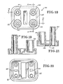
- FIGS. 7-11 there is shown an alternate embodiment of self-sufficient incubation assembly of the present invention indicated by general numerical designation 100.
- the assembly includes a bottom 101 and a top 102, which are essentially shell-like structures, assembled together and provided with required structural rigidity by telescopically interconnecting posts 103 and 104, and posts 105 and 106; posts 103 and 104 being best seen in FIG. 8 and posts 105 and 106 being shown only in FIG. 9 for clarity of invention illustration.
- the assembly 100 further includes a transparent cuvette 110 providing a first cell 111 and a second cell 112, each cell for receiving a portion of a seeded liquid culture growth medium such as eugonic broth seeded with a urine sample from a urinary tract suspected of having a urinary tract infection such as a Gram negative or Gram positive infection.
- a seeded liquid culture growth medium such as eugonic broth seeded with a urine sample from a urinary tract suspected of having a urinary tract infection such as a Gram negative or Gram positive infection.
- the assembly 100 further includes an insulator, of suitable material, indicated by general numerical designation 116 and the two blocks shown in dashed outline in FIGS. 8, 10 and 11; the insulator 116 provides a chamber 120 for receiving the transparent cuvette 110 and insulates the cuvette and seeded liquid culture growth medium received therein during cultivation or incubation.
- the walls of the chamber 120 for receiving the cuvette 110 must be complementary to the external configuration of the cuvette and such is the case in the present invention, and hence it will be understood that the chamber 120 is coincident with the line defining the exterior of the cuvette and hence no physically distinct chamber 120 is shown.
- the insulator 116 is made in two pieces, suitably shaped and assembled together, to provide the intimate contact between the insulator and the cuvette for desired insulation.
- Electrical circuitry as indicated by general numerical designation 130, is included and, in accordance with the further teachings of the present invention, is in intimate physical contact with the under side of the transparent cuvette 110 to provide intimate thermal and optical contact between the. electrical circuitry and cuvette in accordance with the further teachings of the invention.
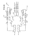
- the electrical circuitry 130 as may be best understood from the diagrammatical illustration of FIG.
- a monolithic chip 132 may include a monolithic chip 132, a film heating resistor 133 for heating the cuvette 110 and seeded culture growth medium received therein to a physiological temperature for the cultivation of microorganisms such as bacteria, a film temperature calibrating resistor 134, a temperature sensing element such as thermistor chip 135 for controlling the heat resistor 133 and thereby controlling to the desired physiological temperature the heat applied to the cuvette and the seeded culture growth medium received therein, a first photoemitter and photodetector pair E1 and D1, a second photoemitter and photodetector pair E2 and D2, and additional photoemitters E3, E4 and E5; it will be understood that upon an understanding of the teachings of the present invention electrical circuitry 130, such as illustrated diagrammatically in FIG.
- the substrate 131 may be of a melamine fiberglass base, a porcelainized metal base, or a ceramic substrate.
- the photoemitters and photodetectors may be suitable available emitter and detector dice suitably bonded to the substrate at appropriate locations as shown; the film resistors may be suitably available such resistors and also suitably deposited on the substrate at appropriate locations as shown; the thermistor chip 135 may be a suitable available semi-conductor thermistor chip suitably bonded to the substrate as shown; and the monolithic chip 132 may be made of any one of several methods known to the prior art and may be made to embody, in combination with the pairs of photoemitters and photodetectors E1 and D1 and E2 and D2, a photometer, such as a turbidity meter, and further embody circuitry for base lining the photometer, temperature monitoring of the cuvette, indicator light illumination of the photoemitters E3, E4 and E5, as well as temperature control of the seed
- the monolithic chip 132 also may be suitably bonded to the substrate 131 and interconnected to the other electrical elements via bonding wires in the manner well known to those skilled in the art. Accordingly, it will be understood that the specific method of manufacture of the electrical circuit 130 is not within the contemplation of the present invention but that such circuitry, upon an understanding of the teachings of the present invention, may be manufactured by any one of several methods well known to those skilled in the art, and upon being so manufactured, embodies a portion of the present combination invention.
- the alternate embodiment also includes an optical system for providing an external indication of the growth of the microorganisms or bacteria within the closed interior of the self-sufficient incubation assembly.
- an optical system for providing an external indication of the growth of the microorganisms or bacteria within the closed interior of the self-sufficient incubation assembly.
- three electro-optical guides G1, G2 and G3 are in physical and electro-optical registration and communication with the photoemitters E3, E4 and E5, respectively, and communicate illumination emanating from these photoemitters to the exterior of the assembly to provide an external visual indication of the detection of growth of microorganisms or bacteria deep within the closed exterior of the assembly.
- the electro-optical light guides G1, G2 and G3 may be supported and positioned, for example, by suitably complementary shaped guideways formed in the insulator 16.
- the cuvette is comprised of a top 160 and a bottom 170 each made of suitable transparent material, such as a suitable transparent moldable plastic, and adhered together by a suitable adhesive or bonding operation; the irregular configuration and closed container aspect of the cuvette 160 require, for cost and convenience of manufacture, that it be made in two pieces, namely the top 160 and bottom 170 and thereafter assembled.
- the top is provided with a pair of upwardly extending intake or entrance galleries 161 and 162 and a pair of shorter and upwardly extending exiting or venting galleries 163 and 164.
- entrance gallery and venting gallery 161 and 163 are associated with cuvette cell 111 and that entrance gallery 162 and venting gallery 164 are associated with cuvette cell 112; hence, the entrance gallery 161 and venting gallery 163 operate as a pair and the entrance gallery 162 and venting gallery 164 operate as a pair. As may be best understood by reference to FIG.
- the upper surface of the cell provided by the lower surface 165 of the top 160, is inclined or angled to insure venting upon filling of the cell with a seeded culture growth liquid medium and in a manner explained in detail later, reflector 166, such as a strip of shiny metal or tape or other suitable surface treatment, is suitably adhered to the top 165 to reflect light from the photoemitter E2 to the photodetector D2; it will be understood that cell 111 is also provided with an inclined top and a reflector 167 as shown in FIG. 20; the reflector 167 is for reflecting light from the photoemitter E1 to the photodetector D1.
- the cuvette bottom 170 is provided with a plurality of integrally formed, upwardly extending walls 171-176 defining cuvette cells 111-112 and the space 113 therebetween.
- the bottom 170 further includes upwardly extending integrally formed meniscus collimating lens 181 and 182 and integrally formed meniscus collecting lens 183 and 184.
- collimating lens 181 and collecting lens 183 are associated with cuvette cell 111 and hence operate as a pair and that collimating lens 182 and collecting lens 184 are associated with cuvette cell 112 and hence operate as a pair; it will be still further understood that collimating lens 181 and collecting lens 183 operate or function in cooperation with reflector 167 and that collimating lens 182 and collecting lens 184 operate or function in cooperation with reflector 166, as shown in FIG. 25. As is further shown in FIG.
- the respective axes of the collimating and collecting lens 182 and 184 are disposed at suitable angles with respect to the reflector 166 (shown in dashed outline but shown where the reflector 166 is positioned upon assembly of the cuvette top and bottom) such that a beam or ray of light collected by lens 182 from photoemitter E2 is focused on the reflector 166 and the reflector reflects the received light along the axis of the collimating lens 184 to the photodetector D2, similarly with regard to collimating and collecting lens 181 and 183, reflector 167 and photoemitter E1 and photodetector D1.
- the bottom 170 is provided with locating pins 188-189 to establish proper registration of the cuvette 110 with the electrical circuitry 130.
- the self-sufficient incubation assembly of the present invention further includes a cap indicated by general numerical designation 150 and which cap is shown in detail in FIGS. 12-14.
- cap 150 has a dual function, namely it seals or closes the cuvette 110 upon a seeded liquid culture growth medium being received therein for microorganism cultivation and also interconnects the electrical circuitry 130 with the battery 144.
- the cap includes a top 151, a plurality of radially disposed and downwardly extending members 153, 154 and 155 for being received in correspondingly radially disposed and downwardly extending slots formed in the top 102 of the assembly 100 as may be best seen in the upper lefthand portion of FIG. 8.
- the cap 150 is provided with a pair of downwardly extending plug members 157 and 158 for respectively entering and sealing the entrance galleries 161 and 162 as is also shown in FIG. 8. It will be further understood that the cap 150 has two positions, the first position with the arrow 159 of the cap (FIG. 12) not aligned with the arrow 119 provided on the top of the assembly as shown in FIG. 7 and in this position the cap does not interconnect the electrical circuitry 130 with the battery 144 and the cap is not locked to the assembly 100.
- the cap is rotated 180° to align the arrows 159 and 119 and the cap is inserted into the top portion of the assembly whereupon the plug members 157 and 158 seal the entrance galleries 161 and 162 and the downwardly extending member 154, as shown in FIG. 8, is provided with an inwardly extending slot or groove which is engaged by the outwardly extending resilient member 152, as shown, to lock the cap 150 to the top 102 of the assembly 100 to close and seal the assembly for incubation.
- the downwardly extending member 155 engages a spring mounted electrical connector 181 to force the connector into engagement with the battery 144 to interconnect the battery 144 through the electrical connector 183 to the electrical circuitry 130 to energize the circuit and commence incubation.
- top 112 is formed inwardly to provide a receptacle 200 which is provided at its bottom with an integrally molded pair of funnels 201 and 202 aligned vertically with the entrance galleries 161 and 162 of the cuvette 110.
- the alternate embodiment self-sufficient incubation assembly 100 of the present invention will now be set forth embodied as a urinary tract infection kit although it will be understood by those skilled in the art that the present invention is not so limited but is of general use with regard to the cultivation of microorganisms such as bacteria.
- bacteria can be classified into two groups, Gram negative and Gram positive bacteria.
- urinary tract infection is caused primarily by Gram negative bacteria such as Ecoli; however, as is also known, urinary tract infection can be caused by Gram positive bacteria.
- Gram negative bacteria reproduce faster than Gram positive bacteria, Gram negative bacteria reproducing approximately every 20 minutes while Gram positive bacteria reproduce approximately every 40 minutes, that is at approximately one half the rate of Gram negative bacteria.
- bacteria in a urine sample from a urinary tract suspected of having an infection may be cultivated at a physiological temperature, such as for example 37°C or 98.6°F, for a given period of time such as for example approximately four hours, and the bacteria level present at the beginning of the period per ml may be compared with the bacteria present per ml at the end of the period and the presence or absence of a clinically significant level of bacteria can be determined.
- the logical determination of the presence of a Gram negative infection or of a Gram positive infection can also be determined or clinically inferred.
- the growth of bacteria in a sample can be determined or measured by the use of a photometer such as a turbidity meter.
- a photometer such as a turbidity meter.
- the optical density of the sample can be measured by passing a transluminating beam or ray of light through the sample and the energy loss due to light scattering of the beam can be measured and recorded.
- Bacteria upon growth or reproduction scatters light and as bacteria in the sample reproduce or proliferate such as in response to cultivation, more light is scattered thereby further increasing the optical density of the sample and hence at the end of the time interval the transluminating beam or ray can again be passed through the sample and the increased energy loss caused by increased optical density or light scattering can again be measured and compared vis-a-vis the earlier measurement.
- the difference in energy level of the light beam can be used, empirically and particularly knowing the reproduction rate of the bacteria present, to provide a measurement of bacteria growth in the sample over the time interval.
- circuitry embodied in the monolithic chip 132 and the photoemitter and photodetector pairs E1-D1 and E2-D2, in combination with the collimating and collecting lens and reflectors of the transparent cuvette 110 function as a photometer or turbidity meter.
- a urine sample has been taken from a urinary tract suspected of having a urinary tract infection, that the urine sample has been diluted in a suitable liquid culture growth medium, such as eugonic broth, to seed the broth, that the cap 150 of the assembly 100 has been removed, and that the seeded liquid culture growth medium has been poured into the receptacle 200 where it flows through the two funnels 201, 202 where it substantially divides and enters into the cells 111 and 112 of the transparent cuvette 110.
- a suitable liquid culture growth medium such as eugonic broth
- cell 111 has been preconditioned to grow only Gram positive bacteria by having a Gram negative inhibitor placed therein such as by coating the walls of cell 111 with sodium azide powder which, as known to those skilled in the art, inhibits the growth of virtually all Gram negative bacteria.
- cell 112 has not been so preconditioned and hence both Gram negative and Gram positive bacteria will grow in cell 112.
- the cap 150 will then be placed into the receptacle 200 with the arrows 119 and 159 aligned to initiate operation of the assembly by energization of the electrical circuit 130 as taught above. It will be understood that the monolithic chip 132 of the electrical circuitry 130, FIG.
- the photoemitters E3, E4 and E5 may have a suitable circuit embodied therein to cause all of the photoemitters E3, E4 and E5 to be temporarily activated, or activated in a predetermined sequence, to provide indication to the user that the self-sufficient incubation assembly is functioning; thereafter such photoemitters will be extinguished and bacteria cultivation commenced and continued for a time interval.
- the photometer or turbidity meter must be baselined to provide appropriate measurement references against which future measurements may be measured or compared for significant results.
- the electrical circuitry 130 of the present invention in accordance with the following further teachings, may be suitably baselined for significant measurements. Referring to FIG. 15, there is shown such baselining circuitry, indicated by general numerical designation 220, which may be used in accordance with the teachings of the present invention and which baselining circuitry, although illustrated as a block diagram in FIG. 15, will be embodied in the monolithic chip 132 of FIG. 16 in a manner known to those skilled in the art.
- the baselining circuitry 220 is a dual channel circuit including channel 230 associated with cuvette cell 111 and channel 240 associated with cuvette cell 112.
- Channel 230 includes the series connection of the photoemitter E1, photodetector D2, amplifier A1, switching network S1, threshold comparator T1, start-stop logic 232, counter 234, digital to analog converter 236 and amplifier A2; similarly, the channel 240 includes the series connected components as shown.
- the baselining circuit includes the threshold comparators T3 and T4 connected to the decoder 250 which in turn is provided with three outputs as shown, for providing one of three binary outputs indicative of the bacterial conditions shown, namely no infection, Gram negative infection, or Gram positive infection.
- the start-stop logic is signalled to stop counting thus freezing the output level of the photoemitter E1 and channel 230 is now baselined; similarly, channel 240 is also baselined to the preset level of threshold detector T2.
- the switching network SW1 assumes state S2 and the evoked response of the photodetector D1 in response to the output of the photemitter E1 transluminating the cuvette cell 111 is connected through amplifier A1 to threshold comparator T3 and compared with its preset threshold level and if the later evoked response of the photodetector D1 falls below the threshold of threshold comparator T3 a binary 0 signal is transmitted to the decoder 250 to indicate the absence of clinically significant Gram positive bacteria growth in cell 111.
- threshold comparator T4 is preset to send a binary 0 or 1 signal to the decoder 250 to respectively indicate the absence of clinically significant levels of Gram negative and/or Gram positive bacteria growth in cell 112 or the presence of clinically significant levels of Gram negative and/or Gram positive bacterial growth in cell 112.
- the preset threshold levels of the respective threshold comparators will be preset empirically and in accordance with the recognized respective reproduction and growth rates of Gram positive and Gram negative bacteria, for example the preset threshold of threshold comparator T4 of channel 240 will be approximately twice the preset level of threshold comparator T3 of channel 230 since it is known that Gram negative bacteria grow at approximately twice the rate of Gram positive bacteria.
- the decoder 250 will interpret or decode the binary 1 or 0 signals received from the respective threshold comparators T3 and T4 to provide an indication of bacterial growth in accordance with the algorithm, sometimes referred to in the art as a truth-table, set forth in FIG. 17. It will be further understood that the algorithm or truth-table of FIG. 17 will also be embodied in suitable circuitry included in the monolithic chip 132 of the electrical circuit 130.
- the decoder it is possible for the decoder to receive a binary 1 from both cell 111 and cell 112 and, as indicated in FIG. 17, this is interpreted or decoded by the decoder 250 to indicate the presence of clinically significant levels of Gram positive bacteria.
- treatment for Gram positive bacteria or Gram positive infection is indicated.
- the temperature of the temperature control element 135 will be substantially the same as the temperature of the cuvette and the seeded culture growth medium contained therein whereby improved temperature control of the medium is provided, and the heat of operation of the electrical circuitry 130 will supplement the heat applied by the heating resistor 133 and battery 144 to the cuvette 110 and the seeded culture growth medium received therein whereby the energy required to be supplied by the battery 144 will be less than would be required were the electrical circuitry 130 to be located externally of the cuvette and not in intimate physical contact therewith.
- the electrical circuitry 72 and the temperature control thermistor included therein are in intimate physical contact with the culture growth dish assembly 60 as shown in FIGS. 5 and 6, specifically the underside thereof, the improved temperature control of the nutrient agar cell is also provided and the heat of operation of the electrical circuitry 72 also supplements the heating of the agar cell by the battery 36.
- the photoemitter E1 of FIG. 16 is positioned at the proper point along the optical axis of the collimating lens 181 of the cuvette 110 to maximize collimation of the light emitted by the photodetector for "transluminating the culture growth medium received by cuvette cell 111 and the photodetector D1 of FIG. 16 is positioned along the optical axis of the collecting lens 183 to maximize the collection of the light transluminating the culture growth medium and exiting the cuvette 110 for photometric measurement.
Landscapes
- Health & Medical Sciences (AREA)
- Chemical & Material Sciences (AREA)
- Wood Science & Technology (AREA)
- Organic Chemistry (AREA)
- Life Sciences & Earth Sciences (AREA)
- Engineering & Computer Science (AREA)
- Bioinformatics & Cheminformatics (AREA)
- Zoology (AREA)
- Biomedical Technology (AREA)
- Sustainable Development (AREA)
- Microbiology (AREA)
- Biotechnology (AREA)
- Biochemistry (AREA)
- General Engineering & Computer Science (AREA)
- General Health & Medical Sciences (AREA)
- Genetics & Genomics (AREA)
- Clinical Laboratory Science (AREA)
- Physics & Mathematics (AREA)
- Thermal Sciences (AREA)
- Analytical Chemistry (AREA)
- Apparatus Associated With Microorganisms And Enzymes (AREA)
Claims (8)
Priority Applications (2)
| Application Number | Priority Date | Filing Date | Title |
|---|---|---|---|
| DE8484114136T DE3476895D1 (en) | 1984-11-22 | 1984-11-22 | Self-sufficient incubation assembly |
| EP19840114136 EP0182926B1 (fr) | 1984-11-22 | 1984-11-22 | Incubateur autonome |
Applications Claiming Priority (1)
| Application Number | Priority Date | Filing Date | Title |
|---|---|---|---|
| EP19840114136 EP0182926B1 (fr) | 1984-11-22 | 1984-11-22 | Incubateur autonome |
Publications (2)
| Publication Number | Publication Date |
|---|---|
| EP0182926A1 EP0182926A1 (fr) | 1986-06-04 |
| EP0182926B1 true EP0182926B1 (fr) | 1989-03-01 |
Family
ID=8192304
Family Applications (1)
| Application Number | Title | Priority Date | Filing Date |
|---|---|---|---|
| EP19840114136 Expired EP0182926B1 (fr) | 1984-11-22 | 1984-11-22 | Incubateur autonome |
Country Status (2)
| Country | Link |
|---|---|
| EP (1) | EP0182926B1 (fr) |
| DE (1) | DE3476895D1 (fr) |
Families Citing this family (10)
| Publication number | Priority date | Publication date | Assignee | Title |
|---|---|---|---|---|
| ATE204322T1 (de) * | 1995-06-07 | 2001-09-15 | Aastrom Biosciences Inc | Vorrichtung und verfahren zum aufbewahren und zur züchtung biologischer zellen |
| US6228635B1 (en) | 1995-06-07 | 2001-05-08 | Aastrom Bioscience, Inc. | Portable cell growth cassette for use in maintaining and growing biological cells |
| US6238908B1 (en) * | 1995-06-07 | 2001-05-29 | Aastrom Biosciences, Inc. | Apparatus and method for maintaining and growth biological cells |
| US5985653A (en) * | 1995-06-07 | 1999-11-16 | Aastrom Biosciences, Inc. | Incubator apparatus for use in a system for maintaining and growing biological cells |
| US6096532A (en) * | 1995-06-07 | 2000-08-01 | Aastrom Biosciences, Inc. | Processor apparatus for use in a system for maintaining and growing biological cells |
| CN102712886A (zh) | 2009-01-30 | 2012-10-03 | 埃米利奥·马特森塔曼斯 | 用于处理和储存细胞培养物的方法及模块设备 |
| TWI417230B (zh) * | 2010-03-03 | 2013-12-01 | Mao Chen Liu | The transporter of the exotic body |
| US10351812B2 (en) | 2015-08-28 | 2019-07-16 | Axion Biosystems, Inc. | Device and system for creating and maintaining a localized environment for a cell culture plate |
| PL421928A1 (pl) * | 2017-06-19 | 2019-01-02 | Bioavlee Spółka Z Ograniczoną Odpowiedzialnością | Przenośne urządzenie inkubacyjne |
| CN113388845B (zh) * | 2021-06-11 | 2023-04-14 | 四川大学 | 微生物-光电化学-热电化学耦合产氢系统 |
Family Cites Families (6)
| Publication number | Priority date | Publication date | Assignee | Title |
|---|---|---|---|---|
| DE1069833B (de) * | 1959-11-26 | Homburg/Saar Hansarnulf von der Mosel | Kulturgcfäß zum Züchten von Mikroorganismen | |
| FR1293616A (fr) * | 1961-04-06 | 1962-05-18 | Rhone Poulenc Sa | Nouveaux dispositifs pour culture des microorganismes et contrôle de leur croissance |
| US3660242A (en) * | 1970-03-05 | 1972-05-02 | Schmid Inc Julius | Incubator |
| GB1324403A (en) * | 1971-04-19 | 1973-07-25 | Poole J A | Portable incubator |
| US4195131A (en) * | 1977-03-09 | 1980-03-25 | Papas Gary R | Environmentally controlled unit |
| US4301252A (en) * | 1980-04-04 | 1981-11-17 | Baker Fraser L | Controlled environment incubator for light microscopy |
-
1984
- 1984-11-22 DE DE8484114136T patent/DE3476895D1/de not_active Expired
- 1984-11-22 EP EP19840114136 patent/EP0182926B1/fr not_active Expired
Also Published As
| Publication number | Publication date |
|---|---|
| DE3476895D1 (en) | 1989-04-06 |
| EP0182926A1 (fr) | 1986-06-04 |
Similar Documents
| Publication | Publication Date | Title |
|---|---|---|
| US4577970A (en) | Cuvette with integral optical elements | |
| US4666853A (en) | Self-sufficient incubation assembly | |
| US4619530A (en) | Combined cuvette with integral optical elements and electrical circuit with photoemissive and photosensitive elements in intimate optical contact with said optical elements | |
| US5164796A (en) | Apparatus and method for detection of microorganisms | |
| EP0182926B1 (fr) | Incubateur autonome | |
| CA2179364C (fr) | Methode et appareil utilises pour detecter les micro-organismes | |
| US5290701A (en) | Microbial detection system and process | |
| CA2105512C (fr) | Detection amelioree de microorganismes dans des echantillons | |
| US5366873A (en) | Device and method for use in detecting microorganisms in a sample | |
| IL42962A (en) | Method and apparatus for determining the effectiveness of antibiotics | |
| EP0472622B1 (fr) | Appareil de detection de micro-organismes | |
| IE48403B1 (en) | Method and apparatus for determining the minimum concentration of antibiotic to inhibit microorganism growth | |
| ATE220109T1 (de) | Schnelles coliform-bestimmungssystem | |
| US20080220439A1 (en) | Microorganism detecting kit, microorganism counting apparatus, and microorganism counting process | |
| WO2004085991A2 (fr) | Analyseur microbiologique utilisant des moyens colorimetriques pour des determinations de couleurs et de croissances biochimiques | |
| IE45434B1 (en) | Diagnostic device | |
| EP0751216B1 (fr) | Récipient pour enchantillons multiples | |
| US20030186350A1 (en) | Microbiological testing method and related apparatus with diffuse-white light emitting diodes | |
| US6197576B1 (en) | Instrument for detection of microorganisms | |
| EP0181962B1 (fr) | Cuvette à éléments optiques intégraux | |
| EP0186712B1 (fr) | Cuvette combinée à des éléments optiques intégrés et circuit électrique à éléments photo-émissifs et photosensibles en contact optique intime avec ces éléments optiques | |
| WO1988007584A1 (fr) | Procede et appareil de detection et de quantification de bacteries | |
| JP2004519235A (ja) | 生物学的検査アレイにおける液体の流れ及び制御 | |
| CN115184285B (zh) | 一种基于多波长反射光谱快速测定细菌总数的装置及其方法 | |
| JPH11178567A (ja) | 細菌検出装置 |
Legal Events
| Date | Code | Title | Description |
|---|---|---|---|
| PUAI | Public reference made under article 153(3) epc to a published international application that has entered the european phase |
Free format text: ORIGINAL CODE: 0009012 |
|
| AK | Designated contracting states |
Kind code of ref document: A1 Designated state(s): CH DE FR GB IT LI NL SE |
|
| 17P | Request for examination filed |
Effective date: 19861022 |
|
| 17Q | First examination report despatched |
Effective date: 19871120 |
|
| GRAA | (expected) grant |
Free format text: ORIGINAL CODE: 0009210 |
|
| AK | Designated contracting states |
Kind code of ref document: B1 Designated state(s): CH DE FR GB IT LI NL SE |
|
| PG25 | Lapsed in a contracting state [announced via postgrant information from national office to epo] |
Ref country code: SE Effective date: 19890301 Ref country code: NL Effective date: 19890301 Ref country code: LI Effective date: 19890301 Ref country code: IT Free format text: LAPSE BECAUSE OF FAILURE TO SUBMIT A TRANSLATION OF THE DESCRIPTION OR TO PAY THE FEE WITHIN THE PRESCRIBED TIME-LIMIT;WARNING: LAPSES OF ITALIAN PATENTS WITH EFFECTIVE DATE BEFORE 2007 MAY HAVE OCCURRED AT ANY TIME BEFORE 2007. THE CORRECT EFFECTIVE DATE MAY BE DIFFERENT FROM THE ONE RECORDED. Effective date: 19890301 Ref country code: CH Effective date: 19890301 |
|
| REF | Corresponds to: |
Ref document number: 3476895 Country of ref document: DE Date of ref document: 19890406 |
|
| REG | Reference to a national code |
Ref country code: CH Ref legal event code: PL |
|
| PGFP | Annual fee paid to national office [announced via postgrant information from national office to epo] |
Ref country code: FR Payment date: 19890721 Year of fee payment: 6 |
|
| PGFP | Annual fee paid to national office [announced via postgrant information from national office to epo] |
Ref country code: DE Payment date: 19890728 Year of fee payment: 6 |
|
| ET | Fr: translation filed | ||
| NLV1 | Nl: lapsed or annulled due to failure to fulfill the requirements of art. 29p and 29m of the patents act | ||
| PGFP | Annual fee paid to national office [announced via postgrant information from national office to epo] |
Ref country code: GB Payment date: 19891130 Year of fee payment: 6 |
|
| PLBE | No opposition filed within time limit |
Free format text: ORIGINAL CODE: 0009261 |
|
| STAA | Information on the status of an ep patent application or granted ep patent |
Free format text: STATUS: NO OPPOSITION FILED WITHIN TIME LIMIT |
|
| 26N | No opposition filed | ||
| PG25 | Lapsed in a contracting state [announced via postgrant information from national office to epo] |
Ref country code: GB Effective date: 19901122 |
|
| GBPC | Gb: european patent ceased through non-payment of renewal fee | ||
| PG25 | Lapsed in a contracting state [announced via postgrant information from national office to epo] |
Ref country code: FR Effective date: 19910731 |
|
| PG25 | Lapsed in a contracting state [announced via postgrant information from national office to epo] |
Ref country code: DE Effective date: 19910801 |
|
| REG | Reference to a national code |
Ref country code: FR Ref legal event code: ST |