EP0182933A1 - Méthode pour l'obtention d'une valeur mesurée du balourd d'un corps ainsi qu'un dispositif à cela - Google Patents
Méthode pour l'obtention d'une valeur mesurée du balourd d'un corps ainsi qu'un dispositif à cela Download PDFInfo
- Publication number
- EP0182933A1 EP0182933A1 EP84114446A EP84114446A EP0182933A1 EP 0182933 A1 EP0182933 A1 EP 0182933A1 EP 84114446 A EP84114446 A EP 84114446A EP 84114446 A EP84114446 A EP 84114446A EP 0182933 A1 EP0182933 A1 EP 0182933A1
- Authority
- EP
- European Patent Office
- Prior art keywords
- unbalance
- unbalance measurement
- value
- line
- measurement value
- Prior art date
- Legal status (The legal status is an assumption and is not a legal conclusion. Google has not performed a legal analysis and makes no representation as to the accuracy of the status listed.)
- Granted
Links
- 238000000034 method Methods 0.000 title claims abstract description 46
- 238000005259 measurement Methods 0.000 claims abstract description 130
- 230000008569 process Effects 0.000 claims abstract description 13
- 230000015654 memory Effects 0.000 claims description 44
- 238000012935 Averaging Methods 0.000 claims description 38
- 238000012545 processing Methods 0.000 claims description 27
- 239000000872 buffer Substances 0.000 claims description 18
- 230000015572 biosynthetic process Effects 0.000 claims description 7
- 230000003389 potentiating effect Effects 0.000 claims description 6
- 238000000605 extraction Methods 0.000 claims description 3
- 239000003795 chemical substances by application Substances 0.000 claims 1
- 230000006872 improvement Effects 0.000 description 2
- 238000012544 monitoring process Methods 0.000 description 2
- 238000005457 optimization Methods 0.000 description 2
- 230000004044 response Effects 0.000 description 2
- 230000000694 effects Effects 0.000 description 1
- 230000006870 function Effects 0.000 description 1
- 230000002452 interceptive effect Effects 0.000 description 1
- 238000012986 modification Methods 0.000 description 1
- 230000004048 modification Effects 0.000 description 1
- MNWBNISUBARLIT-UHFFFAOYSA-N sodium cyanide Chemical compound [Na+].N#[C-] MNWBNISUBARLIT-UHFFFAOYSA-N 0.000 description 1
- 238000004804 winding Methods 0.000 description 1
Images




Classifications
-
- G—PHYSICS
- G01—MEASURING; TESTING
- G01M—TESTING STATIC OR DYNAMIC BALANCE OF MACHINES OR STRUCTURES; TESTING OF STRUCTURES OR APPARATUS, NOT OTHERWISE PROVIDED FOR
- G01M1/00—Testing static or dynamic balance of machines or structures
- G01M1/14—Determining imbalance
- G01M1/16—Determining imbalance by oscillating or rotating the body to be tested
- G01M1/22—Determining imbalance by oscillating or rotating the body to be tested and converting vibrations due to imbalance into electric variables
Definitions
- the invention relates to a method for obtaining an unbalance measurement of a body from a reference signal obtained in an unbalance measurement and at least one measurement signal, the unbalance measurement being available digitally and to a device.
- the above-mentioned DE-OS 24 59 282 proposes to carry out the number of multiplications at least three times, to use digital averaging to represent an unbalance value which, on the one hand, is achieved with measurement times that are as short as possible and, on the other hand, is considered a representative unbalance measurement value.
- the object of the invention is to eliminate counterfeit influences, in particular caused by interference vibrations of other frequencies, in the case of an unbalance measurement value obtained in this way and also to adapt the accuracy of the unbalance measurement value. This object is achieved by the characterizing features of claim 1.
- the influence of disturbance can be determined for the first time vibrations of other frequencies are monitored.
- the deviation of the first measured value from a second measured value can be determined and taken into account if, for example, a bladed turbine rotor is examined for imbalance in a first measurement run, is switched off and is examined again in a second measurement run under the same measurement conditions; Due to the mobility of the turbine blades on the circumference of the turbine base body, it is possible that the turbine blades "settle" in a slightly different form during each measuring run. This different setting will also cause slight differences in the unbalance measurements. Such errors can be minimized by the inventive method according to claim 1 and the last unbalance measurement value thus determined represents the best unbalance measurement value for this component.
- Claim 2 represents an embodiment of claim 1.
- the procedure set out under contactor in claim 4 can influence the influence of the new measured value on the previous measured value.
- Claim 5 teaches instead of the previous moving averaging a non-moving averaging such that the desired number of measurements under the same measurement conditions, ie with the same rotor in several measuring runs or under the same measuring conditions during the same measuring run one after the other and then the sum of all measurements is divided by the number of all measurements and the mean value is thus displayed.
- Claim 6 exposes a potentiation and subsequent rooting of the measured values obtained.
- Claims 7 and 8 take into account the influencing of the newly added values depending on whether the selected exponent is less than or greater than 1.
- claim 9 a non-moving averaging from the extreme values is put under protection and claim 10 represents a moving averaging from the extreme values.
- Claim 11 protects a method in which, depending on a predetermined tolerance, the averaging and thus the optimization of the unbalance measurement of a body can be terminated. In an embodiment of this, it is proposed to preselect the number of shortfalls (claim 12).
- the device claims 13 and 14 show the components for a moving average or the formation of a moving exponential weighted average
- the claims 15, 16 and 17 the components for a non-moving average from the arithmetic mean or the formation of a non-moving exponential weighted average and for a non-moving averaging from the extreme values.
- the characterizing part of claim 18 places a device under protection for the formation of a moving average from the Extreme values and claim 19 discloses a device for tolerance comparison between the new and the previous mean value for aborting the measurement when the tolerance falls below.
- the improvement of the unbalance measurement value originally obtained digitally is achieved by arithmetic averaging, a moving averaging, a geometric averaging, averaging with weighting, averaging using the method of the smallest error powers or by averaging the largest and smallest Unbalance value reached.
- the averaging can take place over a predefined number of further measurement processes, over a predefined time or over a period of time which is given by reaching a state in which the mean value fluctuates only slightly.
- the operator can initiate the end of the averaging or can do it automatically.
- the process of averaging is not limited to a digital determination of the unbalance measurement, but that the monitoring and optimization can also be carried out according to the invention with unbalance measurements obtained digitally.
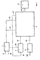
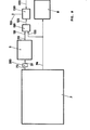
- an unbalance measurement value N ⁇ is fed via a line 201 to a buffer store 6 and from there via a line 62 to an averager 7 in which one of the calculations described later is carried out and the result thereof via a line 74 of a display and / or further processing device 8 is supplied.
- a counter 1 is set to zero via a line 11.
- the counter 1 is started via a further line 14 and counts and stores the number of measurements (n).
- a mean is now formed in the mean value generator 7 from the content of the buffer memory 6 and the content of a memory 2, in which the previous mean value N ⁇ -1 , which in this case is still zero, is stored.
- This mean value obtained in this way which in the exemplary embodiment initially corresponds to the first unbalance measurement value, is displayed in the display and / or further processing device 8, stored in the memory 2 controlled by the counter 1 via line 24, and the buffer memory 6 is then made ready for the recording of a new unbalance measurement value.
- the operator can now judge whether the deviation between the first display in the display and / or further processing device 8 and the second display suggests that larger disturbances are contained in the individual measured values and whether these disturbances which lead to display changes are permissible are. This process can be done like described below, also done automatically. If the result of averaging is not yet satisfactory, the process described above is repeated until the result suggests that further averaging does not bring about an improvement beyond the desired level.
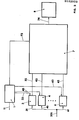
- the non-moving averaging described in FIG. 2 can also be repeated as often as desired and can be ended either manually or automatically, as explained in more detail above.
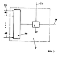
- arithmetic averaging In response to a corresponding command for averaging, arithmetic averaging (FIG. 3), the contents of memories 3 to 6 (FIG. 2) are retrieved from lines n through the lines 32 to 62 and summed up into a totalizer 78. The result of this sum formation is subjected to a division by n in a division circuit 77, where n is the number of measurements which are retrieved from the counter 1 via a line 72. The result is the arithmetic mean and is available for further processing or display in the display and / or further processing device 8 via line 74.
- the content of memory 2 according to FIG. 1, which corresponds to the previous average is called up via line 22 and fed to circuit 75.
- the counter 1 calls up the number of measurements via line 71 via an adder circuit 200 reduced by one (n-1), to a multiplier 75, which multiplies the two values and in an adder circuit 76 to the content of the memory 6 according to FIG. 1, which was called up via a line 62 is added.
- the result of this addition is divided in the division circuit 77 by the number of measurements n carried out (from line 72) and displayed via line 74 in the display and / or further processing device 8 or further processing, for example for controlling a Boring machine.
- the new mean value is stored in the memory 2 by deleting the previous one via the lines 73, 21.
- the exponent can be a predetermined number Z, which is between zero and infinity. If this exponent is less than 1, then new unbalance measurements are taken into account relatively little when averaging, if the exponent is above 1, new unbalance measurements are taken into account relatively strongly. If Z is e.g. 2, a quadratic averaging takes place.
- the content of the memories 3 to 6 potentiating devices 121 to 126 is fed via lines 32 to 62 upon a corresponding start signal for averaging (here, too, the number of Potentiating devices, not limited to the number shown in FIG. 5), in which potentiation takes place.
- the result of this calculation is fed to a totalizer 78, which forms the sum of all results of the calculations in the potentiating devices 121 to 126.
- the content of the summing unit 78 is then fed to a device 79 for forming the root, and then the division circuit 77 again divides by the content of the counter 1 (from line 72).
- the result is fed to the display and / or further processing device 8 via line 74.
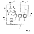
- a device according to FIG. 6 is suitable for the sliding exponentially weighted averaging. This device is again to be considered taking into account the disclosure of FIG. 1.
- the content of the memory 2 is transferred via line 22 to a multiplier 75 for the purpose of multiplication by n-1 (line 71, adder circuit 200) and from there supplied a potentiator 11 0 . This is where the potentiation takes place with the preselected value Z.
- the result of this potentiation is fed to the adder circuit 76.
- the content in the buffer memory 6 is fed to the potentiating device 111 via the line 62 and likewise potentiated. Both results of the exponentiations are added in the adding circuit 76.
- the result of the adder circuit 76 is now fed to a device for root extraction 79, from there to a division circuit 77 for division by n (from line 72).
- the result of this calculation is now available again via line 74 for display and / or further processing and is simultaneously fed via line 73, 21 to memory 2 as new content.
- the device according to FIG. 7 (see also FIG. 2) is supplied with the successively obtained measured values via line 2 0 1.
- Each unbalance measurement value is present via lines 31, 41 ... 61 at all measured value inputs of memories 3, 4 ... 6.
- From counter 1, the position of which indicates the number of the measurement, is via control line 33 or 43 ... or. 63 selected in which memory the relevant unbalance measurement value is stored.
- each new unbalance measurement value is fed via line 201 to comparison circuits 91 and 1 0 1 via 92 or lo2.
- the value is compared with the content of the memory 9o or 1 00 (line 93 or 1 0 3), the content of this memory representing the previously obtained maximum or minimum unbalance measurement values. If a new unbalance measurement value is greater than the content of the memory 9o, the memory 9o is overwritten via the control line 94 with the value present via the line 95. If the new unbalance measurement value is less than the content of the memory 100, the content of the memory 100 with the value present on line 105 is overwritten instead via the control line 1 0 4. If the new measured value is neither greater than the largest value obtained to date nor smaller than the smallest value obtained so far, it is ignored.
- NaCN completion of the measurements of the content of the memory is supplied to 90 and 100 of an adder circuit 153 via lines 96 and 1 0 6, the result is then divided in the divider circuit with fixed quotient 154 by the value two and, as already described above, to display and / or further processing device 8 passed via line 74; at the same time this value is fed to the memory 2 via the line 73, 21.
- a device for automatically determining the termination of the averaging when a predetermined tolerance is reached is explained in FIG. It is assumed that according to the previously described ways of averaging the output of the averager 7, a new average is present on line 74 and a previous average is stored in memory 2.
- a delay circuit 2 03 on line 73 evaluates that before storing the new mean in Memory 2 the new average and the previous average for comparison of a comparison circuit 12o are supplied via lines 122 and 121, respectively. In this comparison circuit, the difference between the new and the previous average is first formed and this is fed via line 123 to a tolerance comparison circuit 13o.
- a value is entered into this via a line 132, which is determined by the operator and determines the value at which the measurement is terminated when the difference between the unbalance measurement values is undershot. This can be, for example, a fraction of the balancing tolerance required for the rotor to be examined. If the value falls below the corresponding value in the tolerance comparison circuit 13o, a signal is emitted via a line 133, which automatically terminates the measuring process and, if necessary, brakes the balancing machine.
Landscapes
- Physics & Mathematics (AREA)
- General Physics & Mathematics (AREA)
- Testing Of Balance (AREA)
Priority Applications (3)
| Application Number | Priority Date | Filing Date | Title |
|---|---|---|---|
| DE8484114446T DE3478820D1 (en) | 1984-11-29 | 1984-11-29 | Method for getting a measuring value of unbalanced mass of a body as well as device concerning this |
| EP19840114446 EP0182933B1 (fr) | 1984-11-29 | 1984-11-29 | Méthode pour l'obtention d'une valeur mesurée du balourd d'un corps ainsi qu'un dispositif à cela |
| JP25647185A JPS61132834A (ja) | 1984-11-29 | 1985-11-14 | 不つりあい測定方法およびその装置 |
Applications Claiming Priority (1)
| Application Number | Priority Date | Filing Date | Title |
|---|---|---|---|
| EP19840114446 EP0182933B1 (fr) | 1984-11-29 | 1984-11-29 | Méthode pour l'obtention d'une valeur mesurée du balourd d'un corps ainsi qu'un dispositif à cela |
Publications (2)
| Publication Number | Publication Date |
|---|---|
| EP0182933A1 true EP0182933A1 (fr) | 1986-06-04 |
| EP0182933B1 EP0182933B1 (fr) | 1989-06-28 |
Family
ID=8192316
Family Applications (1)
| Application Number | Title | Priority Date | Filing Date |
|---|---|---|---|
| EP19840114446 Expired EP0182933B1 (fr) | 1984-11-29 | 1984-11-29 | Méthode pour l'obtention d'une valeur mesurée du balourd d'un corps ainsi qu'un dispositif à cela |
Country Status (3)
| Country | Link |
|---|---|
| EP (1) | EP0182933B1 (fr) |
| JP (1) | JPS61132834A (fr) |
| DE (1) | DE3478820D1 (fr) |
Cited By (2)
| Publication number | Priority date | Publication date | Assignee | Title |
|---|---|---|---|---|
| EP0628798A1 (fr) * | 1993-06-07 | 1994-12-14 | SCHENCK RoTec GmbH | Procédé d'élimination des valeurs de mesure non-utiles d'un signal de mesure de balourd |
| CN1828250B (zh) * | 2005-03-02 | 2010-06-16 | 西门子公司 | 识别系统的稳定建立的方法 |
Families Citing this family (2)
| Publication number | Priority date | Publication date | Assignee | Title |
|---|---|---|---|---|
| JP4823795B2 (ja) * | 2006-07-24 | 2011-11-24 | 株式会社リコー | 画像読取装置 |
| JP5257762B2 (ja) * | 2008-08-11 | 2013-08-07 | 株式会社Ihi | 高速回転体の回転バランス計測装置及び方法 |
Citations (1)
| Publication number | Priority date | Publication date | Assignee | Title |
|---|---|---|---|---|
| DE2459282A1 (de) * | 1974-12-14 | 1976-06-16 | Schenck Ag Carl | Auswuchtverfahren und anordnung zur durchfuehrung des verfahrens |
Family Cites Families (1)
| Publication number | Priority date | Publication date | Assignee | Title |
|---|---|---|---|---|
| JPS59222740A (ja) * | 1983-06-02 | 1984-12-14 | Kougi Kenkyusho:Kk | 車輪アンバランス測定方法 |
-
1984
- 1984-11-29 DE DE8484114446T patent/DE3478820D1/de not_active Expired
- 1984-11-29 EP EP19840114446 patent/EP0182933B1/fr not_active Expired
-
1985
- 1985-11-14 JP JP25647185A patent/JPS61132834A/ja active Pending
Patent Citations (1)
| Publication number | Priority date | Publication date | Assignee | Title |
|---|---|---|---|---|
| DE2459282A1 (de) * | 1974-12-14 | 1976-06-16 | Schenck Ag Carl | Auswuchtverfahren und anordnung zur durchfuehrung des verfahrens |
Cited By (2)
| Publication number | Priority date | Publication date | Assignee | Title |
|---|---|---|---|---|
| EP0628798A1 (fr) * | 1993-06-07 | 1994-12-14 | SCHENCK RoTec GmbH | Procédé d'élimination des valeurs de mesure non-utiles d'un signal de mesure de balourd |
| CN1828250B (zh) * | 2005-03-02 | 2010-06-16 | 西门子公司 | 识别系统的稳定建立的方法 |
Also Published As
| Publication number | Publication date |
|---|---|
| DE3478820D1 (en) | 1989-08-03 |
| EP0182933B1 (fr) | 1989-06-28 |
| JPS61132834A (ja) | 1986-06-20 |
Similar Documents
| Publication | Publication Date | Title |
|---|---|---|
| DE2459282C2 (fr) | ||
| DE69228517T2 (de) | Simulator mit Anwendung eines Neuronalnetzwerkes | |
| DE3048508A1 (de) | Kombinationswiegeeinrichtung | |
| DE2853560A1 (de) | Vorrichtung zur berechnung mehrerer interpolationsgroessen und eine solche vorrichtung verwendende tomographievorrichtung | |
| DE2605485A1 (de) | Verfahren und vorrichtung zur ueberwachung und/oder korrektur einer kenngroesse, insbesondere des auswuchtzustandes von werkstuecken | |
| DE2804454C2 (fr) | ||
| DE2615966C3 (de) | Fehlermessung in Digital-Systemen | |
| DE3152398C2 (de) | Vorrichtung zum Zusammenstellen von Artikeln | |
| DE3152246T1 (fr) | ||
| EP0182933B1 (fr) | Méthode pour l'obtention d'une valeur mesurée du balourd d'un corps ainsi qu'un dispositif à cela | |
| DE3911830A1 (de) | Verfahren und schaltung zur auswertung von kontinuierlich auftretenden zeitmarken | |
| EP0234273A2 (fr) | Equipement électronique testable et méthode de test pour un tel équipement | |
| DE2462451A1 (de) | Vorrichtung zum messen und vergleichen von drehzahlen | |
| DE3306214C2 (fr) | ||
| DE3889034T2 (de) | Verfahren zum Reduzieren der lateralen Kraftschwankungen eines Reifens. | |
| DE3425472A1 (de) | Verfahren und vorrichtung zur digitalen bestimmung der zahl der umdrehungen sich drehender koerper | |
| DE1939125B2 (de) | Vorrichtung zur anzeige der schichtdicke eines in einem elektrolytischen bad abgeschiedenen stoffes | |
| DE2448309A1 (de) | Verfahren zum bestimmen von zu einer bestimmten einschaltdauer eines roentgenstrahlers gehoerigen spannungs- und stromwerten und eine schaltung zum durchfuehren dieses verfahrens | |
| DE2946581C2 (de) | Verfahren und Schaltungsanordnung zur Beseitigung von Unwuchten an Rotationskörpern | |
| DE69013459T2 (de) | Messverfahren für die Gleichstrom/Gleichspannungs-Charakteristik von Halbleiterbauteilen. | |
| DE69217371T2 (de) | Einstellung eines elektrischen potentials durch automatische titrierung | |
| DE3743302C2 (de) | Verfahren zur Bestimmung einer Korrektur in mindestens einer Korrekturebene, die nicht die Bezugsebene ist, zum Ausgleich einer in einem auszuwuchtenden Körper vorhandenen Unwucht sowie Vorrichtung zur Durchführung des Verfahrens | |
| DE2805989C2 (de) | Selbsttätige Steuerung für den Schaltmotor von elektromechanischen, selbsteinspielenden Waagen | |
| DE3039933C2 (fr) | ||
| DE2831624A1 (de) | Verfahren zum dosieren von stroemenden medien und vorrichtung zur durchfuehrung des verfahrens |
Legal Events
| Date | Code | Title | Description |
|---|---|---|---|
| PUAI | Public reference made under article 153(3) epc to a published international application that has entered the european phase |
Free format text: ORIGINAL CODE: 0009012 |
|
| AK | Designated contracting states |
Kind code of ref document: A1 Designated state(s): AT BE CH DE FR GB IT LI LU NL SE |
|
| 17P | Request for examination filed |
Effective date: 19860604 |
|
| RBV | Designated contracting states (corrected) |
Designated state(s): DE FR GB IT |
|
| RBV | Designated contracting states (corrected) |
Designated state(s): DE FR GB IT |
|
| 17Q | First examination report despatched |
Effective date: 19870922 |
|
| ITF | It: translation for a ep patent filed | ||
| GRAA | (expected) grant |
Free format text: ORIGINAL CODE: 0009210 |
|
| AK | Designated contracting states |
Kind code of ref document: B1 Designated state(s): DE FR GB IT |
|
| REF | Corresponds to: |
Ref document number: 3478820 Country of ref document: DE Date of ref document: 19890803 |
|
| ET | Fr: translation filed | ||
| GBT | Gb: translation of ep patent filed (gb section 77(6)(a)/1977) | ||
| PLBI | Opposition filed |
Free format text: ORIGINAL CODE: 0009260 |
|
| PLBI | Opposition filed |
Free format text: ORIGINAL CODE: 0009260 |
|
| 26 | Opposition filed |
Opponent name: HOFMANN WERKSTATT-TECHNIK GMBH Effective date: 19900316 |
|
| 26 | Opposition filed |
Opponent name: DR. REUTLINGER + SOEHNE GMBH & CO KG Effective date: 19900326 Opponent name: HOFMANN WERKSTATT-TECHNIK GMBH Effective date: 19900316 |
|
| PLBM | Termination of opposition procedure: date of legal effect published |
Free format text: ORIGINAL CODE: 0009276 |
|
| STAA | Information on the status of an ep patent application or granted ep patent |
Free format text: STATUS: OPPOSITION PROCEDURE CLOSED |
|
| 27C | Opposition proceedings terminated |
Effective date: 19910706 |
|
| ITTA | It: last paid annual fee | ||
| PGFP | Annual fee paid to national office [announced via postgrant information from national office to epo] |
Ref country code: FR Payment date: 19951009 Year of fee payment: 12 |
|
| PGFP | Annual fee paid to national office [announced via postgrant information from national office to epo] |
Ref country code: GB Payment date: 19951017 Year of fee payment: 12 |
|
| PGFP | Annual fee paid to national office [announced via postgrant information from national office to epo] |
Ref country code: DE Payment date: 19951019 Year of fee payment: 12 |
|
| PG25 | Lapsed in a contracting state [announced via postgrant information from national office to epo] |
Ref country code: GB Effective date: 19961129 |
|
| GBPC | Gb: european patent ceased through non-payment of renewal fee |
Effective date: 19961129 |
|
| PG25 | Lapsed in a contracting state [announced via postgrant information from national office to epo] |
Ref country code: FR Effective date: 19970731 |
|
| PG25 | Lapsed in a contracting state [announced via postgrant information from national office to epo] |
Ref country code: DE Effective date: 19970801 |
|
| REG | Reference to a national code |
Ref country code: FR Ref legal event code: ST |