EP0182945A1 - Appareil pour la découpe d'ébauches à rives latérales en zigzag et pour enrouler les ébauches - Google Patents
Appareil pour la découpe d'ébauches à rives latérales en zigzag et pour enrouler les ébauches Download PDFInfo
- Publication number
- EP0182945A1 EP0182945A1 EP84308229A EP84308229A EP0182945A1 EP 0182945 A1 EP0182945 A1 EP 0182945A1 EP 84308229 A EP84308229 A EP 84308229A EP 84308229 A EP84308229 A EP 84308229A EP 0182945 A1 EP0182945 A1 EP 0182945A1
- Authority
- EP
- European Patent Office
- Prior art keywords
- strips
- station
- scroll
- slitting
- arbor
- Prior art date
- Legal status (The legal status is an assumption and is not a legal conclusion. Google has not performed a legal analysis and makes no representation as to the accuracy of the status listed.)
- Withdrawn
Links
Images

Classifications
-
- B—PERFORMING OPERATIONS; TRANSPORTING
- B21—MECHANICAL METAL-WORKING WITHOUT ESSENTIALLY REMOVING MATERIAL; PUNCHING METAL
- B21C—MANUFACTURE OF METAL SHEETS, WIRE, RODS, TUBES, PROFILES OR LIKE SEMI-MANUFACTURED PRODUCTS OTHERWISE THAN BY ROLLING; AUXILIARY OPERATIONS USED IN CONNECTION WITH METAL-WORKING WITHOUT ESSENTIALLY REMOVING MATERIAL
- B21C47/00—Winding-up, coiling or winding-off metal wire, metal band or other flexible metal material characterised by features relevant to metal processing only
- B21C47/006—Winding-up, coiling or winding-off metal wire, metal band or other flexible metal material characterised by features relevant to metal processing only winding-up or winding-off several parallel metal bands
-
- B—PERFORMING OPERATIONS; TRANSPORTING
- B23—MACHINE TOOLS; METAL-WORKING NOT OTHERWISE PROVIDED FOR
- B23D—PLANING; SLOTTING; SHEARING; BROACHING; SAWING; FILING; SCRAPING; LIKE OPERATIONS FOR WORKING METAL BY REMOVING MATERIAL, NOT OTHERWISE PROVIDED FOR
- B23D19/00—Shearing machines or shearing devices cutting by rotary discs
- B23D19/04—Shearing machines or shearing devices cutting by rotary discs having rotary shearing discs arranged in co-operating pairs
- B23D19/06—Shearing machines or shearing devices cutting by rotary discs having rotary shearing discs arranged in co-operating pairs with several spaced pairs of shearing discs working simultaneously, e.g. for trimming or making strips
- B23D19/065—Shearing machines or shearing devices cutting by rotary discs having rotary shearing discs arranged in co-operating pairs with several spaced pairs of shearing discs working simultaneously, e.g. for trimming or making strips for cutting along lines not parallel to the longitudinal direction of the material, e.g. oblique or zig-zag cutting
-
- B—PERFORMING OPERATIONS; TRANSPORTING
- B65—CONVEYING; PACKING; STORING; HANDLING THIN OR FILAMENTARY MATERIAL
- B65H—HANDLING THIN OR FILAMENTARY MATERIAL, e.g. SHEETS, WEBS, CABLES
- B65H18/00—Winding webs
- B65H18/08—Web-winding mechanisms
- B65H18/10—Mechanisms in which power is applied to web-roll spindle
- B65H18/103—Reel-to-reel type web winding and unwinding mechanisms
-
- B—PERFORMING OPERATIONS; TRANSPORTING
- B65—CONVEYING; PACKING; STORING; HANDLING THIN OR FILAMENTARY MATERIAL
- B65H—HANDLING THIN OR FILAMENTARY MATERIAL, e.g. SHEETS, WEBS, CABLES
- B65H18/00—Winding webs
- B65H18/08—Web-winding mechanisms
- B65H18/10—Mechanisms in which power is applied to web-roll spindle
- B65H18/106—Mechanisms in which power is applied to web-roll spindle for several juxtaposed strips
Definitions
- This invention relates to a slitting machine and particularly to a slitting machine or apparatus for scroll slitting a web of sheet metal or similar material into multiple scrolls or strips having scroll shaped edges.
- Slitting lines basically consist of an uncoiler from which a wide web of sheet metal is unwound from a coil, a slitter which slits the webs into a plurality of strips, and a recoiling mechanism which recoils or winds the plurality of strips onto one or more arbors.
- the slitting mechanism typically includes upper and lower arbors which are rotatably mounted in housings.
- Each arbor includes a plurality of rotary cutting members positioned so that the cutting members on the upper arbor intermesh or mate with the cutting members on the lower arbor to provide a scissors-like cutting or slitting operation upon a web or metallic material.
- the rotary cutting members mounted on the arbors are all essentially disc shaped,, having circular cutting edges.
- the cutting members or knives are provided with serpentine or sinuous cutting edges. Slitters of this latter type are known as scroll slitters.
- a slitting and rewinding apparatus in accordance with this invention comprises a scroll slitting station including a pair of spaced arbors and a plurality of pairs of mating scroll slitting knives mounted upon said arbors, each of said scroll slitting knives having a serpentine shaped scroll slitting knife edge for cutting said web of sheet stock material into multiple scroll slit strips and a recoiling station located downstream from said slitting station, said recoiling station including means for supporting a single rewind arbor and means for driving said rewind arbor in rotation to rewind all of the scroll slit strips of said web of stock material onto said single arbor without any overlap of said strips on said single Harbor.
- a looping pit is provided between the slitting station and the recoiler or rewind station of a scroll slitting line and guide spaces are provided between the strips in the slack strips as those strips emerge from the looping pit and before tension is placed upon the strips for feed onto the rewind or recoiler mandrel.
- those strips may be moved laterally relative to the centre strips so as to provide spacing between the strips at least equal to the amplitude of the sinuous scroll on the edge of the strips. Rewinding tension is only placed on the strips after this spacing is achieved in the slack strips. As so spaced then, the strips may all be wound upon a common recoiler mandrel.
- Such apparatus enables all of the scroll slit strips to be rewound upon a common mandrel without any overlap of the scroll shaped edges of the multiple strips and to incorporate only a single rewind recoiler operable to rewind all of the scroll slit strips of a common web upon a single common mandrel.
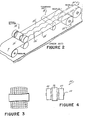
- FIG. 1 there is illustrated a scroll slitting line 10 incorporating the invention of this application.
- This line 10 compirses an uncoiler station 12, a scroll slitting station 14, a looping pit 16, a tensioning station 18, and a recoiling station 20.
- a spacing station 22 Immediately upstream of the tensioning station 18, and as explained more fully hereinafter, there are stationary spacers located at a spacing station 22 for establishing a gap between the scroll slit strips 24, 26 and 28 cut from the web 30 of rolled sheet metal stock metal.
- the uncoiler 12 is conventional and forms no part of the invention of this application. Basically, it comprises a motor driven mandrel upon which a coil of web stock 10 is mounted for feed into the scroll slitter.
- the scroll slitter 14 is also, for purposes of this application, conventional and per se forms no part of the invention of this application.
- One scroll slitter suitable for use in this application is fully disclosed in U.S. Patent Application Serial No. 393,832, filed June 30, 1982, and assigned to the assignee of this application.
- Other scroll slitters suitable for use in this application are disclosed in U.S. Patent No. 3,517,532 and U.S. Patent No. 3,388,582.
- the scroll slitter 14 includes a pair of motor driven arbors 34, 36 upon which there are mounted pairs of mating knives 38,40. These knives 38, 40 have intermeshing scroll shaped or sinusoidal wave shaped edges 42 which overlap to form a scissors-like cutting action of any material, such as the web of stock material 30 passed between the knives 38, 40. As illustrated in Figure 1, three strips 24,26 and 28 of scroll slit material result from passage between the knives 38,40 of the scroll slitter 14. The scissors cutting action of these knives 38 and 40 forms scroll or sinusoidal shaped edges 44 on the strip 24, 26 and 28.
- the centremost strip 26 has a scroll shaped edge on both sides of the strip while the edgemost strips 24 and 28 have only a single scroll or sinusoidal shaped edge.
- the outer edges of the outermost strips 24 and 28 may have a similar scroll configuration imparted thereto or a greater number of strips could be formed having either one or both side edges of the strips cut into a scroll configuration.
- the strips After emerging from the scroll slitting station 14 the strips pass over a series of supporting rollers 46 into a looping pit 16.
- This pit extends a substantial distance below the floor level of the slitting line 10.
- the depth of the looping pit is a function of the length of the coils of web material 30 to be slit on the line. Longer strips of thin stock material require deeper pits than do heavier gauge stock material which are shorter in overall length. In our preferred embodiment of this invention, the pit extends approximately twenty feet below the floor level.
- the looping pit 16 serves a dual function of (a) facilitating tensioning of all three strips 24, 26 and 28 on the recoiler while differing lengths of strips are wound thereon, and (b) of permitting all three strips to be gapped a distance slightly greater than the amplitude of the scroll or sinusoidal shaped edge imparted to the strips so as to enable all of the strips to be wound onto a common mandrel 50.
- a characteristic of all rolled metal webs is that to some degree "crown" is present in every web or strip or rolled sheet metal.
- the webs are all thicker in the centre than at either edge, so that when viewed in cross section, the strip or web 30 is always convex, like a lens, instead of having parallel top and bottom surfaces.
- This crown is illustrated in Figure 3 wherein in the top half of the diagram, the crown is accentuated as if all of the cross sections of the web were equally under compression.
- the lower half of the diagram of Figure 3 better illustrates the manner in which the web 30 is rolled onto a mandrel with the centre sections of the strip tightly wound and the outer edges of the strip more loosely wound.
- the looping pit 16 and tension device 18 are provided between the scroll slitter head 14 and the recoiler 20.
- the provision of the looping pit upstream of the tensioning unit allows the thinner, looser outer strips to "mark time" until they can be rewound with the tight centre wraps. Additionally, the looping pit relieves all of the strips 24, 26 and 28 of any tension between the scroll slitter 14 and the tension unit 18 so that the strips may be fanned apart a distance slightly greater than the amplitude of the sinuous edge of the strips and thereby rewound upon a common mandrel 50.
- the valleys of one strip do not mate with the peaks of the adjacent strip. Therefore, unless the three strips are fanned apart a distance at least as great as the amplitude of the sinuous edge 44 on the strips, the strips will be overlapped when wound upon a common recoiler.
- spacers 54, 56 located upstream of the tensioning unit at the point at which the strips emerge from the looping pit.
- these spacers 54, 56 are attached to the same frame (not shown) which supports a series of rollers 58 over which the strip is guided as it emerges from the pit and before it passes into the tensioning unit 18.
- the tensioning unit 18 comprises a stationary bottom pad 59 and an upper pad 61 movable downwardly under hydraulic pressure toward the stationary pad 59.
- both these pads have a fabric material, as for example an outdoor rug type fabric applied to the top surface of the lower pad and the bottom surface of the upper pad.
- These pressure pads flatten the strips and establish alignment of the strips before the strips pass into tensioning rollers 63 and 65 at tension station 18.
- These tensioning rollers are conventional rubber or friction material covered rollers which have a brake applied thereto so as to tension each of the strips as those strips are pulled onto the mandrel 50 of the motor driven recoiler 20.
- the braking force applied to the rollers 63 and 65 of the tensioning unit 18 determines the tension applied to the strips as the strips are rewound onto the mandrel 50.
- FIG. 2 there is illustrated a prior art scroll slitting line 10'.
- it has been the practice to feed the strips of scroll slit material 24' 26' and 28' directly from the scroll slitter 14' through a tensioning unit 18' and onto a pair of recoilers 20'-1 and 20'-2 the first or upstream recoiler 20'-1 of which is operable to wind the two outermost strips 24', 28' of scroll slit material while the downstream most recoiler 20'-2 winds the centre strip 26'.
- a web 30 of rolled stock material is unwound from a coil of sheet metal stock and passed through a scroll slitting station 14.
- the strips 24, 26 and 28 created by passage through the scroll slitter 14, or at least the outermost strips 24 and 28 are festooned into the looping pit following the slitter and prior to passage of the strips through the tensioning unit 18.
- the strips may be gapped or fanned apart horizontally before the strips are fed into the tensioner 18.
- This spacing or lateral fanning of the strips is accomplished by the stationary spacers 54, 56 which are adjustable and set to gap each strip sufficiently far apart that the serpentine or wave-shaped edges can be wound onto a single mandrel 50 of a recoiler alongside each other without interference or overlap of the edges of adjacent strips.
- the spacers 54, 56 are critically spaced at the high point and exit side of the looping pit where no recoiling tension is applied to the strip. Consequently, the strips may be moved laterally or sideways at this point without damage so as to establish the appropriate gap between the strips.
- the strips are squeezed between the fabric lined wipe pads 59, 61 under a predetermined hydraulic pressure. This pressure flattens the strips and prevents any further relative lateral movement between the strips as they then are passed between the tensioning rollers 63, 65.
- the tensioning rollers are connected to a conventional braking system operable to establish a predetermined tension on the strips as the strips are pulled between the tensioning rollers and onto the driven mandrel 50 of the recoiler. Since the strips are tensioned while recoiled, all strips are wound under tension with a very straight wall thereby eliminating the possibility of interleaving of adjacent serpentine shaped edges of the strips. Consequently, the strips are all wound with the same horizontal gap between the strips as was fixed by the guides 54 and 56.
Landscapes
- Engineering & Computer Science (AREA)
- Mechanical Engineering (AREA)
- Winding, Rewinding, Material Storage Devices (AREA)
Priority Applications (1)
| Application Number | Priority Date | Filing Date | Title |
|---|---|---|---|
| EP84308229A EP0182945A1 (fr) | 1984-11-28 | 1984-11-28 | Appareil pour la découpe d'ébauches à rives latérales en zigzag et pour enrouler les ébauches |
Applications Claiming Priority (1)
| Application Number | Priority Date | Filing Date | Title |
|---|---|---|---|
| EP84308229A EP0182945A1 (fr) | 1984-11-28 | 1984-11-28 | Appareil pour la découpe d'ébauches à rives latérales en zigzag et pour enrouler les ébauches |
Publications (1)
| Publication Number | Publication Date |
|---|---|
| EP0182945A1 true EP0182945A1 (fr) | 1986-06-04 |
Family
ID=8192824
Family Applications (1)
| Application Number | Title | Priority Date | Filing Date |
|---|---|---|---|
| EP84308229A Withdrawn EP0182945A1 (fr) | 1984-11-28 | 1984-11-28 | Appareil pour la découpe d'ébauches à rives latérales en zigzag et pour enrouler les ébauches |
Country Status (1)
| Country | Link |
|---|---|
| EP (1) | EP0182945A1 (fr) |
Cited By (3)
| Publication number | Priority date | Publication date | Assignee | Title |
|---|---|---|---|---|
| ES2062917A2 (es) * | 1992-10-01 | 1994-12-16 | Bayarri Carmen Vazquez | Maquina para la produccion de rollos de cinta sin mandril, y rollo de cinta obtenido por dicha maquina. |
| WO2003022476A1 (fr) * | 2001-09-13 | 2003-03-20 | Alcan International Limited | Procede et dispositif de production de bandes a partir d'une feuille |
| CN112620840A (zh) * | 2020-12-08 | 2021-04-09 | 吉林大学 | 用于预应力高压模具缠绕的狭缝调整定位装置及制备方法 |
Citations (6)
| Publication number | Priority date | Publication date | Assignee | Title |
|---|---|---|---|---|
| US2849193A (en) * | 1956-01-26 | 1958-08-26 | Reynolds Metals Co | Apparatus for slitting aluminum webs and rewinding strips therefrom |
| FR1468856A (fr) * | 1965-10-18 | 1967-02-10 | Alcan Aluminium France | Perfectionnements à l'enroulement de bandes métalliques à la sortie d'une ligne de refendage |
| US3388582A (en) * | 1965-09-27 | 1968-06-18 | Bendix Corp | Apparatus for slitting sheet metal and method of forming circular members therefrom |
| US3517532A (en) * | 1965-09-27 | 1970-06-30 | Bendix Corp | Apparatus for slitting sheet metal and method of forming circular members therefrom |
| US3628367A (en) * | 1969-12-12 | 1971-12-21 | Littell Machine Co F J | Scroll cutting and slitting machine with tension control means |
| DE2355241A1 (de) * | 1973-11-05 | 1975-05-15 | Gianni Ausenda | Verfahren zur herstellung von flacheisen fuer stabroste mit profiliertem rand und rundmesser zur durchfuehrung des verfahrens auf einer schermaschine |
-
1984
- 1984-11-28 EP EP84308229A patent/EP0182945A1/fr not_active Withdrawn
Patent Citations (6)
| Publication number | Priority date | Publication date | Assignee | Title |
|---|---|---|---|---|
| US2849193A (en) * | 1956-01-26 | 1958-08-26 | Reynolds Metals Co | Apparatus for slitting aluminum webs and rewinding strips therefrom |
| US3388582A (en) * | 1965-09-27 | 1968-06-18 | Bendix Corp | Apparatus for slitting sheet metal and method of forming circular members therefrom |
| US3517532A (en) * | 1965-09-27 | 1970-06-30 | Bendix Corp | Apparatus for slitting sheet metal and method of forming circular members therefrom |
| FR1468856A (fr) * | 1965-10-18 | 1967-02-10 | Alcan Aluminium France | Perfectionnements à l'enroulement de bandes métalliques à la sortie d'une ligne de refendage |
| US3628367A (en) * | 1969-12-12 | 1971-12-21 | Littell Machine Co F J | Scroll cutting and slitting machine with tension control means |
| DE2355241A1 (de) * | 1973-11-05 | 1975-05-15 | Gianni Ausenda | Verfahren zur herstellung von flacheisen fuer stabroste mit profiliertem rand und rundmesser zur durchfuehrung des verfahrens auf einer schermaschine |
Cited By (3)
| Publication number | Priority date | Publication date | Assignee | Title |
|---|---|---|---|---|
| ES2062917A2 (es) * | 1992-10-01 | 1994-12-16 | Bayarri Carmen Vazquez | Maquina para la produccion de rollos de cinta sin mandril, y rollo de cinta obtenido por dicha maquina. |
| WO2003022476A1 (fr) * | 2001-09-13 | 2003-03-20 | Alcan International Limited | Procede et dispositif de production de bandes a partir d'une feuille |
| CN112620840A (zh) * | 2020-12-08 | 2021-04-09 | 吉林大学 | 用于预应力高压模具缠绕的狭缝调整定位装置及制备方法 |
Similar Documents
| Publication | Publication Date | Title |
|---|---|---|
| US4170691A (en) | Steel metal web handling method, apparatus, and coil construct | |
| US4173313A (en) | Metal web handling method, apparatus and coil construct | |
| US4508282A (en) | Scroll slitting and rewind apparatus | |
| CA1037378A (fr) | Appareil de fendage pour de materiaux en bobines | |
| US2849193A (en) | Apparatus for slitting aluminum webs and rewinding strips therefrom | |
| EP0182945A1 (fr) | Appareil pour la découpe d'ébauches à rives latérales en zigzag et pour enrouler les ébauches | |
| EP2119653B1 (fr) | Bobineuse destinée à enrouler une bande de feuille fine, notamment une bande d'aluminium | |
| CA1221304A (fr) | Dispositif de decoupage de feuillard et de rebobinage du produit | |
| US2275093A (en) | Method and apparatus for manufacturing strip | |
| US4523364A (en) | High speed production of multiple gauge strip | |
| RU2082518C1 (ru) | Устройство для смотки в рулоны полосовой стали | |
| US3017694A (en) | Metal bending method and product | |
| RU2220801C2 (ru) | Моталка для тонкой металлической ленты | |
| US11208285B2 (en) | Brake device and method for operating a brake device | |
| EP2390211B1 (fr) | Appareil pour dérouler et couper longitudinalement une bande de matériau | |
| CA1088486A (fr) | Methode et appareil pour la manipulation des feuilles metalliques enroulees | |
| EP1356887B1 (fr) | Dispositif pour sectionner une ébauche en forme de bande ayant des lignes d'affaiblissement | |
| DE29611251U1 (de) | Vorrichtung zum Auf- oder Abwickeln einer Faserstoff-Bahn | |
| JP3033627B2 (ja) | 金属条のスリッティング装置 | |
| US4760947A (en) | Slitter strand separating roll | |
| JP3011345B2 (ja) | スリッタラインに於ける通板方法 | |
| CN219173836U (zh) | 一种不锈钢带分条裁切用薄板防跳动输送装置 | |
| CN219885276U (zh) | 一种卷材分切装置 | |
| CN112533709A (zh) | 卷轴装置以及具备其的轧制设备及轧制方法 | |
| JP3274417B2 (ja) | 銅合金条材巻取り方法 |
Legal Events
| Date | Code | Title | Description |
|---|---|---|---|
| PUAI | Public reference made under article 153(3) epc to a published international application that has entered the european phase |
Free format text: ORIGINAL CODE: 0009012 |
|
| AK | Designated contracting states |
Kind code of ref document: A1 Designated state(s): CH DE FR GB LI |
|
| 17P | Request for examination filed |
Effective date: 19860911 |
|
| 17Q | First examination report despatched |
Effective date: 19871204 |
|
| STAA | Information on the status of an ep patent application or granted ep patent |
Free format text: STATUS: THE APPLICATION IS DEEMED TO BE WITHDRAWN |
|
| 18D | Application deemed to be withdrawn |
Effective date: 19890214 |
|
| RIN1 | Information on inventor provided before grant (corrected) |
Inventor name: EITING, JOHN RALPH |