EP0182997B1 - Appareil de mesure - Google Patents
Appareil de mesure Download PDFInfo
- Publication number
- EP0182997B1 EP0182997B1 EP85112055A EP85112055A EP0182997B1 EP 0182997 B1 EP0182997 B1 EP 0182997B1 EP 85112055 A EP85112055 A EP 85112055A EP 85112055 A EP85112055 A EP 85112055A EP 0182997 B1 EP0182997 B1 EP 0182997B1
- Authority
- EP
- European Patent Office
- Prior art keywords
- layer
- graduation
- forming
- piezoelectric material
- measuring arrangement
- Prior art date
- Legal status (The legal status is an assumption and is not a legal conclusion. Google has not performed a legal analysis and makes no representation as to the accuracy of the status listed.)
- Expired
Links
- 239000000463 material Substances 0.000 claims abstract description 19
- 230000005291 magnetic effect Effects 0.000 claims abstract description 12
- 239000010410 layer Substances 0.000 description 39
- 238000005259 measurement Methods 0.000 description 9
- 238000002347 injection Methods 0.000 description 3
- 239000007924 injection Substances 0.000 description 3
- 238000000034 method Methods 0.000 description 3
- 239000012790 adhesive layer Substances 0.000 description 2
- 239000000919 ceramic Substances 0.000 description 2
- 230000001419 dependent effect Effects 0.000 description 2
- 238000001514 detection method Methods 0.000 description 2
- 238000004519 manufacturing process Methods 0.000 description 2
- 238000012935 Averaging Methods 0.000 description 1
- 230000003321 amplification Effects 0.000 description 1
- JRPBQTZRNDNNOP-UHFFFAOYSA-N barium titanate Chemical compound [Ba+2].[Ba+2].[O-][Ti]([O-])([O-])[O-] JRPBQTZRNDNNOP-UHFFFAOYSA-N 0.000 description 1
- 229910002113 barium titanate Inorganic materials 0.000 description 1
- 238000010276 construction Methods 0.000 description 1
- 230000000694 effects Effects 0.000 description 1
- 238000005530 etching Methods 0.000 description 1
- 239000004922 lacquer Substances 0.000 description 1
- 238000011326 mechanical measurement Methods 0.000 description 1
- 238000003199 nucleic acid amplification method Methods 0.000 description 1
- 239000002907 paramagnetic material Substances 0.000 description 1
Images
Classifications
-
- G—PHYSICS
- G01—MEASURING; TESTING
- G01B—MEASURING LENGTH, THICKNESS OR SIMILAR LINEAR DIMENSIONS; MEASURING ANGLES; MEASURING AREAS; MEASURING IRREGULARITIES OF SURFACES OR CONTOURS
- G01B7/00—Measuring arrangements characterised by the use of electric or magnetic techniques
- G01B7/003—Measuring arrangements characterised by the use of electric or magnetic techniques for measuring position, not involving coordinate determination
-
- G—PHYSICS
- G01—MEASURING; TESTING
- G01B—MEASURING LENGTH, THICKNESS OR SIMILAR LINEAR DIMENSIONS; MEASURING ANGLES; MEASURING AREAS; MEASURING IRREGULARITIES OF SURFACES OR CONTOURS
- G01B7/00—Measuring arrangements characterised by the use of electric or magnetic techniques
- G01B7/02—Measuring arrangements characterised by the use of electric or magnetic techniques for measuring length, width or thickness
-
- G—PHYSICS
- G01—MEASURING; TESTING
- G01B—MEASURING LENGTH, THICKNESS OR SIMILAR LINEAR DIMENSIONS; MEASURING ANGLES; MEASURING AREAS; MEASURING IRREGULARITIES OF SURFACES OR CONTOURS
- G01B7/00—Measuring arrangements characterised by the use of electric or magnetic techniques
- G01B7/30—Measuring arrangements characterised by the use of electric or magnetic techniques for measuring angles or tapers; for testing the alignment of axes
Definitions
- the invention relates to a measuring arrangement according to the preamble of claim 1.
- DE-PS 32 03 933 describes an arrangement in which a shaft is provided with at least one pin or a cam which acts on a spring associated with a piezo-ceramic body in such a way that measurement signals are generated when the shaft is rotated on the piezo-ceramic body that depend on the angular position of the shaft.
- DE-B 3316581 shows a device for measuring the injection jets of high-pressure injection valves with regard to the jet quantity and the jet position.
- two strip-shaped sensors in a V arrangement are rotatably provided in a rotationally symmetrical receiving space.
- the jet position is determined from the point of exit at the injection nozzle and the point of impact at the sensors in the receiving space in cooperation with angle signals from a rotary position sensor.
- the receiving space can be equipped with individual sensors like a mosaic, which must be individually provided with lead-out terminals to the Strahlla to detect g e. All of these disclosed arrangements are not suitable for detecting the change in position of two objects that are movable relative to one another.
- DE-B 28 31 939 shows a transducer with a piezoelectric measuring element for measuring mechanical quantities on hollow bodies.
- a layer package is attached to the outer surface of a tube and an electrically conductive contact surface of the piezoelectric film in the layer package is subdivided into a plurality of electrically separate strips running parallel to one another, as a result of which the movement of a body in the tube can be determined.
- a lot of force is required to influence the piezoelectric material, since the moving body in the tube must first stretch the tube itself and the force is transmitted to the piezoelectric material via the relatively thick and inert tube wall.
- the invention has for its object to provide a piezoelectric measuring arrangement of the type mentioned, through which a high resolution is achieved with relatively simple structural means and an interference-free, compact arrangement.
- the advantages achieved with the invention consist in particular in that the structuring is possible with conventional means of a known type, since the division is integrated in the form of a thin layer in the layer package, and thus a high resolution can be implemented inexpensively.
- the division-forming thin layer into the layer package, it is possible to influence several division elements at the same time and to obtain an easily evaluable measurement signal without a primary signal to be controlled.
- the possibility of constructing the layer package from thin layers makes it easy to influence and contactless scanning by using a magnetic force-exerting element.
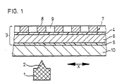
- FIG. 1 schematically shows a section of a linear measuring arrangement with a structured magnet 1 as a force-exerting element.
- the structuring of the magnet 1 takes place by means of a raised magnetic pole 2.
- a layer package 3 is assigned to the magnet 1 in a relatively movable manner in the measuring direction X.
- This magnet 1 is connected in a manner not shown to the tool slide of a machine tool, the layer package 3 being fixedly attached to the machine tool relative to it.
- the layer package 3 consists of two contact layers 4, 5 with an intermediate layer of piezoelectric material 6.
- On the contact layer 4, a division-forming layer 7 is arranged, which consists of ferro- or paramagnetic material. The division is formed by magnetically influenceable and non-influenceable areas 8 and 9 which are arranged alternately.
- a support layer 10 serves as an abutment for the complete layer package 3. If there is a relative movement between the magnetic pole 2 and the layer package 3 in the measuring direction X, the magnetically influenceable regions 8 and non-influenceable regions 9 alternately pass through high field line densities, as a result of which the magnetically influenceable regions 8 perpendicular to the division plane be deflected. As a result, the piezoelectric material 6 is deformed alternately and a piezo voltage modulated in proportion to the change in pressure can be tapped at the contact layers 4, 5 as a measurement signal.
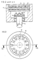
- the structure of the layer package 11 corresponds. analogous to the structure of Figure 1, only that in this case the magnetically influenceable and not influenceable areas 12 and 13 are arranged as a division-forming layer on a circle.
- a rotatable magnet 15 attached to a shaft 14 has a plurality of magnetic poles 16. When the magnet 15 rotates with respect to the layer package 1, the tongue-like magnetically influenceable areas 12 press on the supported piezoelectric material 17 due to the action of the magnet.
- Lithographic processes, etching processes or galvanic application processes are preferred as production processes for producing the division.
- Offset signals for direction detection and / or coded measurement signals are obtained by using adjacent, mutually insulated, division-embodying contact layers which are contacted separately; or through the separate contacting of individual isolated dividing elements.
- the position-dependent charge changes generated on the surfaces of the piezoelectric material are conducted outward through the contact layers or directly via the conductive support layer and the division-forming layer.
- the contact layers can be vapor-deposited, can consist of conductive lacquer, a conductive film or can be galvanically constructed.
Landscapes
- Physics & Mathematics (AREA)
- General Physics & Mathematics (AREA)
- Measurement Of Length, Angles, Or The Like Using Electric Or Magnetic Means (AREA)
- Force Measurement Appropriate To Specific Purposes (AREA)
- Transmission And Conversion Of Sensor Element Output (AREA)
- Printers Or Recording Devices Using Electromagnetic And Radiation Means (AREA)
Claims (7)
Priority Applications (1)
| Application Number | Priority Date | Filing Date | Title |
|---|---|---|---|
| AT85112055T ATE41514T1 (de) | 1984-11-27 | 1985-09-24 | Messanordnung. |
Applications Claiming Priority (2)
| Application Number | Priority Date | Filing Date | Title |
|---|---|---|---|
| DE3443133 | 1984-11-27 | ||
| DE3443133A DE3443133C1 (de) | 1984-11-27 | 1984-11-27 | Messanordnung |
Publications (2)
| Publication Number | Publication Date |
|---|---|
| EP0182997A1 EP0182997A1 (fr) | 1986-06-04 |
| EP0182997B1 true EP0182997B1 (fr) | 1989-03-15 |
Family
ID=6251220
Family Applications (1)
| Application Number | Title | Priority Date | Filing Date |
|---|---|---|---|
| EP85112055A Expired EP0182997B1 (fr) | 1984-11-27 | 1985-09-24 | Appareil de mesure |
Country Status (3)
| Country | Link |
|---|---|
| EP (1) | EP0182997B1 (fr) |
| AT (1) | ATE41514T1 (fr) |
| DE (2) | DE3443133C1 (fr) |
Families Citing this family (4)
| Publication number | Priority date | Publication date | Assignee | Title |
|---|---|---|---|---|
| GB2170605B (en) * | 1985-02-06 | 1988-08-17 | Lucas Ind Plc | Transducers |
| DE8706578U1 (de) * | 1987-05-07 | 1988-06-09 | Siemens Ag, 1000 Berlin Und 8000 Muenchen | Taktiler Sensor |
| US7002310B2 (en) * | 2004-02-25 | 2006-02-21 | Somfy Sas | Piezo-based encoder with magnetic brake for powered window covering |
| DE102014100435B4 (de) * | 2014-01-16 | 2017-04-06 | Deutsches Zentrum für Luft- und Raumfahrt e.V. | Sensor und Linearbewegungsanordnung |
Family Cites Families (8)
| Publication number | Priority date | Publication date | Assignee | Title |
|---|---|---|---|---|
| DE2726312B2 (de) * | 1977-06-10 | 1981-01-29 | Rafi Gmbh & Co Elektrotechnische Spezialfabrik, 7981 Berg | Meßumformer mit einer piezoeristiven Anordnung |
| AT375466B (de) * | 1977-07-27 | 1984-08-10 | List Hans | Messwertaufnehmer mit einem piezoelektrischen messelement |
| FR2520498A1 (fr) * | 1982-01-27 | 1983-07-29 | Boussois Sa | Procede pour determiner les coordonnees d'un point sur une surface et dispositif pour sa mise en oeuvre |
| DE3203933C2 (de) * | 1982-02-05 | 1983-12-01 | Siemens AG, 1000 Berlin und 8000 München | Anordnung zum Erfassen einer mechanischen Größe |
| US4521685A (en) * | 1982-03-01 | 1985-06-04 | Lord Corporation | Tactile sensor for an industrial robot or the like |
| US4484026A (en) * | 1983-03-15 | 1984-11-20 | Koala Technologies Corporation | Touch tablet data device |
| DE3316581C1 (de) * | 1983-05-06 | 1984-10-04 | Daimler-Benz Ag, 7000 Stuttgart | Einrichtung zur Vermessung der Einspritzstrahlen von Hochdruck-Einspritzventilen |
| DE3330325A1 (de) * | 1983-08-23 | 1985-03-14 | Licentia Gmbh | Zeichentablett, insbesondere zur informationsuebertragung einer graphischen darstellung |
-
1984
- 1984-11-27 DE DE3443133A patent/DE3443133C1/de not_active Expired
-
1985
- 1985-09-24 AT AT85112055T patent/ATE41514T1/de not_active IP Right Cessation
- 1985-09-24 DE DE8585112055T patent/DE3568866D1/de not_active Expired
- 1985-09-24 EP EP85112055A patent/EP0182997B1/fr not_active Expired
Also Published As
| Publication number | Publication date |
|---|---|
| EP0182997A1 (fr) | 1986-06-04 |
| DE3443133C1 (de) | 1986-02-27 |
| ATE41514T1 (de) | 1989-04-15 |
| DE3568866D1 (en) | 1989-04-20 |
Similar Documents
| Publication | Publication Date | Title |
|---|---|---|
| EP1222471B1 (fr) | Systeme de mesure avec element de mesure d'acceleration et element de mesure de position | |
| DE3882962T2 (de) | Multidrehungs-Positionsgeber. | |
| EP0877916B1 (fr) | Procede et dispositif de mesure angulaire pour corps rotatifs | |
| DE69618559T2 (de) | Kapazitiver Abstandssensor, insbesondere zur Erfassung von Fingerabdrücken | |
| DE2817544C2 (fr) | ||
| DE4309442C2 (de) | Passiver berührungsloser magnetischer Positionssensor | |
| DE19851839B4 (de) | Magnetfelddetektor | |
| EP1565755B1 (fr) | Detecteur de position | |
| DE4016434A1 (de) | Kapazitiver stellungsgeber | |
| EP0493385B1 (fr) | Codeur haute resolution | |
| DE19534995A1 (de) | Sensor zur Lenkradwinkelerfassung | |
| DE2523163A1 (de) | Kapazitiver differentialmesswandler | |
| DE3308352A1 (de) | Magnetdetektorvorrichtung | |
| DE4306487C2 (de) | Verfahren und Vorrichtung zum Detektieren einer Drehbewegung eines mit einer drehenden Welle verbundenen Objekts | |
| EP2182330A2 (fr) | Système de mesure de position/trajectoire doté d'un corps de mesure codé | |
| DE19601242A1 (de) | Versatz-Erfassungseinrichtung | |
| DE69213573T2 (de) | Messgerät linearer Verschiebung und Dehnung | |
| EP0204712A1 (fr) | Procede d'ajustage pour un organe detecteur de position, en particulier dans un vehicule a moteur. | |
| DE10044839A1 (de) | Induktiver Positionssensor | |
| DE19612422C2 (de) | Potentiometereinrichtung mit einem linear verschiebbaren Stellelement und signalerzeugenden Mitteln | |
| EP0182997B1 (fr) | Appareil de mesure | |
| DE4233331A1 (de) | Anordnung zur Bestimmung von Positionen | |
| WO1998057127A1 (fr) | Detecteur de course | |
| DE3803293A1 (de) | Magnetisch betaetigter analoger elektrischer wegaufnehmer fuer geradlinige bewegungen | |
| DE4219907C2 (de) | Magnetischer Sensor |
Legal Events
| Date | Code | Title | Description |
|---|---|---|---|
| PUAI | Public reference made under article 153(3) epc to a published international application that has entered the european phase |
Free format text: ORIGINAL CODE: 0009012 |
|
| 17P | Request for examination filed |
Effective date: 19851008 |
|
| AK | Designated contracting states |
Kind code of ref document: A1 Designated state(s): AT CH DE FR GB IT LI NL SE |
|
| 17Q | First examination report despatched |
Effective date: 19870723 |
|
| ITF | It: translation for a ep patent filed | ||
| GRAA | (expected) grant |
Free format text: ORIGINAL CODE: 0009210 |
|
| AK | Designated contracting states |
Kind code of ref document: B1 Designated state(s): AT CH DE FR GB IT LI NL SE |
|
| REF | Corresponds to: |
Ref document number: 41514 Country of ref document: AT Date of ref document: 19890415 Kind code of ref document: T |
|
| GBT | Gb: translation of ep patent filed (gb section 77(6)(a)/1977) | ||
| REF | Corresponds to: |
Ref document number: 3568866 Country of ref document: DE Date of ref document: 19890420 |
|
| ET | Fr: translation filed | ||
| PLBE | No opposition filed within time limit |
Free format text: ORIGINAL CODE: 0009261 |
|
| STAA | Information on the status of an ep patent application or granted ep patent |
Free format text: STATUS: NO OPPOSITION FILED WITHIN TIME LIMIT |
|
| 26N | No opposition filed | ||
| PGFP | Annual fee paid to national office [announced via postgrant information from national office to epo] |
Ref country code: FR Payment date: 19900816 Year of fee payment: 6 |
|
| PGFP | Annual fee paid to national office [announced via postgrant information from national office to epo] |
Ref country code: GB Payment date: 19900820 Year of fee payment: 6 Ref country code: CH Payment date: 19900820 Year of fee payment: 6 |
|
| PGFP | Annual fee paid to national office [announced via postgrant information from national office to epo] |
Ref country code: SE Payment date: 19900821 Year of fee payment: 6 |
|
| PGFP | Annual fee paid to national office [announced via postgrant information from national office to epo] |
Ref country code: AT Payment date: 19900828 Year of fee payment: 6 |
|
| ITTA | It: last paid annual fee | ||
| PGFP | Annual fee paid to national office [announced via postgrant information from national office to epo] |
Ref country code: NL Payment date: 19900930 Year of fee payment: 6 |
|
| PG25 | Lapsed in a contracting state [announced via postgrant information from national office to epo] |
Ref country code: GB Effective date: 19910924 Ref country code: AT Effective date: 19910924 |
|
| PG25 | Lapsed in a contracting state [announced via postgrant information from national office to epo] |
Ref country code: SE Effective date: 19910925 |
|
| PG25 | Lapsed in a contracting state [announced via postgrant information from national office to epo] |
Ref country code: LI Effective date: 19910930 Ref country code: CH Effective date: 19910930 |
|
| PG25 | Lapsed in a contracting state [announced via postgrant information from national office to epo] |
Ref country code: NL Effective date: 19920401 |
|
| NLV4 | Nl: lapsed or anulled due to non-payment of the annual fee | ||
| GBPC | Gb: european patent ceased through non-payment of renewal fee | ||
| PG25 | Lapsed in a contracting state [announced via postgrant information from national office to epo] |
Ref country code: FR Effective date: 19920529 |
|
| REG | Reference to a national code |
Ref country code: CH Ref legal event code: PL |
|
| REG | Reference to a national code |
Ref country code: FR Ref legal event code: ST |
|
| PGFP | Annual fee paid to national office [announced via postgrant information from national office to epo] |
Ref country code: DE Payment date: 19920817 Year of fee payment: 8 |
|
| PG25 | Lapsed in a contracting state [announced via postgrant information from national office to epo] |
Ref country code: DE Effective date: 19940601 |
|
| EUG | Se: european patent has lapsed |
Ref document number: 85112055.0 Effective date: 19920408 |