EP0183038A2 - Einrichtung zum Einspritzen von Kraftstoff in Brennräume von insbesondere selbstzündenden Brennkraftmaschinen - Google Patents
Einrichtung zum Einspritzen von Kraftstoff in Brennräume von insbesondere selbstzündenden Brennkraftmaschinen Download PDFInfo
- Publication number
- EP0183038A2 EP0183038A2 EP85113156A EP85113156A EP0183038A2 EP 0183038 A2 EP0183038 A2 EP 0183038A2 EP 85113156 A EP85113156 A EP 85113156A EP 85113156 A EP85113156 A EP 85113156A EP 0183038 A2 EP0183038 A2 EP 0183038A2
- Authority
- EP
- European Patent Office
- Prior art keywords
- temperature
- exhaust gas
- controlled
- glow
- gas temperature
- Prior art date
- Legal status (The legal status is an assumption and is not a legal conclusion. Google has not performed a legal analysis and makes no representation as to the accuracy of the status listed.)
- Withdrawn
Links
Images
Classifications
-
- F—MECHANICAL ENGINEERING; LIGHTING; HEATING; WEAPONS; BLASTING
- F02—COMBUSTION ENGINES; HOT-GAS OR COMBUSTION-PRODUCT ENGINE PLANTS
- F02D—CONTROLLING COMBUSTION ENGINES
- F02D41/00—Electrical control of supply of combustible mixture or its constituents
- F02D41/02—Circuit arrangements for generating control signals
- F02D41/14—Introducing closed-loop corrections
- F02D41/1438—Introducing closed-loop corrections using means for determining characteristics of the combustion gases; Sensors therefor
- F02D41/1444—Introducing closed-loop corrections using means for determining characteristics of the combustion gases; Sensors therefor characterised by the characteristics of the combustion gases
- F02D41/1446—Introducing closed-loop corrections using means for determining characteristics of the combustion gases; Sensors therefor characterised by the characteristics of the combustion gases the characteristics being exhaust temperatures
-
- F—MECHANICAL ENGINEERING; LIGHTING; HEATING; WEAPONS; BLASTING
- F02—COMBUSTION ENGINES; HOT-GAS OR COMBUSTION-PRODUCT ENGINE PLANTS
- F02D—CONTROLLING COMBUSTION ENGINES
- F02D35/00—Controlling engines, dependent on conditions exterior or interior to engines, not otherwise provided for
- F02D35/0015—Controlling engines, dependent on conditions exterior or interior to engines, not otherwise provided for using exhaust gas sensors
-
- F—MECHANICAL ENGINEERING; LIGHTING; HEATING; WEAPONS; BLASTING
- F02—COMBUSTION ENGINES; HOT-GAS OR COMBUSTION-PRODUCT ENGINE PLANTS
- F02P—IGNITION, OTHER THAN COMPRESSION IGNITION, FOR INTERNAL-COMBUSTION ENGINES; TESTING OF IGNITION TIMING IN COMPRESSION-IGNITION ENGINES
- F02P13/00—Sparking plugs structurally combined with other parts of internal-combustion engines
-
- F—MECHANICAL ENGINEERING; LIGHTING; HEATING; WEAPONS; BLASTING
- F02—COMBUSTION ENGINES; HOT-GAS OR COMBUSTION-PRODUCT ENGINE PLANTS
- F02P—IGNITION, OTHER THAN COMPRESSION IGNITION, FOR INTERNAL-COMBUSTION ENGINES; TESTING OF IGNITION TIMING IN COMPRESSION-IGNITION ENGINES
- F02P19/00—Incandescent ignition, e.g. during starting of internal combustion engines; Combination of incandescent and spark ignition
- F02P19/02—Incandescent ignition, e.g. during starting of internal combustion engines; Combination of incandescent and spark ignition electric, e.g. layout of circuits of apparatus having glowing plugs
-
- F—MECHANICAL ENGINEERING; LIGHTING; HEATING; WEAPONS; BLASTING
- F02—COMBUSTION ENGINES; HOT-GAS OR COMBUSTION-PRODUCT ENGINE PLANTS
- F02B—INTERNAL-COMBUSTION PISTON ENGINES; COMBUSTION ENGINES IN GENERAL
- F02B3/00—Engines characterised by air compression and subsequent fuel addition
- F02B3/06—Engines characterised by air compression and subsequent fuel addition with compression ignition
Definitions
- the invention relates to a device for injecting fuel according to the preamble of the main claim.
- the glow element consists of a material whose electrical resistance value is temperature-dependent. This material property is used to simultaneously assign the function of a sensor for an evaluation circuit for the combustion process to the incandescent body.
- the incandescent body from a material with a temperature-dependent resistance value even in the devices of the generic type and to use the respective resistance value of the incandescent body to regulate the temperature of the incandescent body.
- the precious metal platinum and its alloys would be preferred as the material because, in addition to the required electrical properties, it also the other bean can withstand spells in the combustion chamber.
- these precious metals are expensive and the other, much cheaper heat and corrosion-resistant heating conductor materials have the property that their electrical resistance value depends only to a very small extent or not at all on the temperature, which makes temperature control impossible in the event of a changing ambient temperature because of the Radiator is cooled or heated even without power supply.
- the device according to the invention with the characterizing features of the main claim has the advantage that the annealing temperature can be controlled without the incandescent body having to be made of a noble metal. If an exhaust gas temperature sensor is already present in the machine, no additional circuitry measures are required apart from a corresponding addition to the control unit.
- a map for the exhaust gas temperature as a function of the load and speed can be determined for each machine. Through experiments, an optimal glow element temperature can be assigned to each exhaust gas temperature and the control voltage or heating current required to achieve this glow element temperature can be determined.
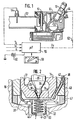
- Figure 1 shows part of an internal combustion engine in section and the associated control means for the glow plug in a schematic representation.
- Figure 2 the combustion chamber end of the injector of Figure 1 and the downstream glow plug are shown in section.
- the device according to the invention has an injection nozzle 10 which is installed in the cylinder head 12 of an internal combustion engine.
- the injection nozzle 10 has a nozzle body 14 which is clamped to a nozzle holder by a union nut 16.
- a valve seat 18 is formed in the nozzle body 14 and a valve needle 20 is slidably mounted.
- the nozzle body 14 contains a fuel channel 22 which opens into a pressure chamber 26 surrounding the valve needle 20 in the region of a pressure shoulder 24.
- the increasing fuel pressure in the pressure chamber 26 lifts the valve needle 20 against the force of a closing spring, not shown, from the valve seat 18, after which the fuel reaches the combustion chamber in the form of a spray jet 27.
- One helical end 34 is through a recess 36 in the housing 28 performed and connected to a conductor 38 which is guided via a glass melt 40 and a longitudinal groove 42 in the union nut 16 and is connected to an external connection 44 ( Figure 1).
- the other coil end 46 of the incandescent body 32 is connected to the housing 28 and, via this, the union nut 16, a sealing ring 47 and the cylinder head 12 to ground.
- Bores 48, 49 are provided in the housing 28, through which the spray jets 27 suck air from the combustion chamber into the glow body 32, where there is good premixing of the air with the fuel, at least in peripheral zones of the spray jets.
- an exhaust valve 51 is arranged at the beginning of an exhaust pipe 52, in which a temperature sensor 54 is installed.
- the output signal T A of the temperature sensor 54 is fed to a control unit 56, which is programmed in accordance with the data of an engine map 58.
- a signal n corresponding to the rotational speed and a signal T K corresponding to the cooling water temperature are fed to the control unit 56.
- a current source 60 feeds a heating circuit 62, which leads to the spray opening of the injection nozzle 10 via the control device 56 and the glow body 32.
- the incandescent body 32 is heated to a greater or lesser extent by the combustion gases depending on the speed and load.
- This thermal load on the incandescent body 32 which is caused by environmental influences, is detected according to the invention by measuring the exhaust gas temperature and in the control unit 56 to form a current in the heating circuit 62 regulating output signal U v processed. This can preferably be done in such a way that the heating current is controlled in accordance with the temperature difference between the prevailing exhaust gas temperature and a glow element temperature assigned to this exhaust gas temperature as intended.
- the speed signal n and / or the load-dependent signal T K can also be used as further information for forming the output signal U V.
- the glow attachments are preferably connected in parallel to the control unit 56.
Landscapes
- Engineering & Computer Science (AREA)
- Chemical & Material Sciences (AREA)
- Combustion & Propulsion (AREA)
- Mechanical Engineering (AREA)
- General Engineering & Computer Science (AREA)
- Ignition Installations For Internal Combustion Engines (AREA)
- Combustion Methods Of Internal-Combustion Engines (AREA)
- Fuel-Injection Apparatus (AREA)
Abstract
Description
- Die Erfindung geht aus von einer Einrichtung zum Einspritzen von Kraftstoff nach der Gattung des Hauptanspruchs. Bei einer bekannten Einrichtung mit einer Einspritzdüse und einem Glühvorsatz (DE-A1 33 29 379) besteht das Glühelement aus einem Material, dessen elektrischer Widerstandswert temperaturabhängig ist. Diese Materialeigenschaft wird dazu genutzt, den Glühkörper gleichzeitig die Funktion eines Meßwertgebers für eine Auswerteschaltung für den Verbrennungsablauf zuzuordnen.
- Es liegt nahe, auch bei den Einrichtungen der gattungsmäßigen Art den Glühkörper aus einem Material mit temperaturabhängigem Widerstandswert zu fertigen und den jeweiligen Widerstandswert des Glühkörpers zur Regelung der Glühkörpertemperatur heranzuziehen. Als Material käme bevorzugt das Edelmetall Platin und dessen Legierungen infrage, weil es neben den geforderten elektrischen Eigenschaften auch den anderen Beanspruchungen im Brennraum standzuhalten vermag. Diese Edelmetalle sind jedoch teuer und die anderen, wesentlich billigeren hitze- und korrosionsbeständigen Heizleiterwerkstoffe haben die Eigenschaft, daß ihr elektrischer Widerstandswert nur in sehr geringem Maße oder überhaupt nicht von der Temperatur abhängig ist, was eine Temperaturregelung bei einer wechselnden Umgebungstemperatur unmöglich macht, weil der Heizkörper dabei selbst ohne Stromzuführung gekühlt bzw. aufgeheizt wird.
- Die erfindungsgemäße Einrichtung mit den kennzeichnenden Merkmalen des Hauptanspruchs hat demgegenüber den Vorteil, daß eine Steuerung der Glühtemperatur erfolgen kann, ohne daß der Glühkörper aus einem Edelmetall gefertigt sein muß. Wenn ein Abgas-Temperaturfühlter in der Maschine bereits vorhanden ist, so sind außer einer entsprechenden Ergänzung des Steuergerätes keine weiteren zusätzlichen Schaltungsmaßnahmen erforderlich.
- Für jede Maschine kann ein Kennfeld für die Abgastemperatur als Funktion der Last und Drehzahl ermittelt werden. Durch Versuche kann jeder Abgastemperatur eine optimale Glühkörpertemperatur zugeordnet und die zum Erreichen dieser Glühkörpertemperatur erforderliche Steuerspannung bzw. Heizstromstärke festgelegt werden.
- Bei einer bevorzugten Ausführung können darüberhinaus weitere Betriebsparameter, wie Drehzahl, Kühlwassertemperatur, mittlerer Arbeitsdruck usw. zusätzlich verarbeitet werden.
- Ein Ausführungsbeispiel der Erfindung ist in der Zeichnung dargestellt und in der nachfolgenden Beschreibung näher erläutert. Figur 1 zeigt einen Teil einer Brennkraftmaschine im Schnitt und die dazugehörenden Steuermittel für den Glühvorsatz in schematischer Darstellung. In Figur 2 ist das brennraumseitige Ende der Einspritzdüse nach Figur 1 und der nachgeschaltete Glühvorsatz im Schnitt dargestellt.
- Die erfindungsgemäße Einrichtung hat eine Einspritzdüse 10, die in den Zylinderkopf 12 einer Brennkraftmaschine eingebaut ist. Die Einspritzdüse 10 hat gemäß Figur 2 einen Düsenkörper 14, der durch eine Überwurfmutter 16 an einem Düsenhalter festgespannt ist. Im Düsenkörper 14 ist ein Ventilsitz 18 gebildet und eine Ventilnadel 20 verschiebbar gelagert. Der Düsenkörper 14 enthält einen Kraftstoffkanal 22, der in einem die Ventilnadel 20 im Bereich einer Druckschulter 24 umgebenden Druckraum 26 mündet. Bei Einspritzbeginn hebt der ansteigende Kraftstoffdruck im Druckraum 26 die Ventilnadel 20 entgegen der Kraft einer nicht dargestellten Schließfeder vom Ventilsitz 18 ab, wonach der Kraftstoff in Form eines Spritzstrahles 27 in den Brennraum gelangt.
- An der Überwurfmutter 16 ist brennraumseitig das Gehäuse 28 eines Glühvorsatzes 30 befestigt, dessen Glühkörper 32 als Drahtwendel ausgebildet ist. Das eine Wendelende 34 ist durch eine Aussparung 36 des Gehäuses 28 hindurchgeführt und mit einem Leiter 38 verbunden, der über eine Glaseinschmelzung 40 und eine Längsnut 42 in der Überwurfmutter 16 geführt und mit einem externen Anschluß 44 (Figur 1) verbunden ist. Das andere Wendelende 46 des Glühkörpers 32 ist mit dem Gehäuse 28 und über dieses, die Überwurfmutter 16, einen Dichtring 47 und den Zylinderkopf 12 mit Masse verbunden. Im Gehäuse 28 sind Bohrungen 48, 49 vorgesehen, durch welche die Spritzstrahlen 27 Luft aus dem Brennraum in den Glühkörper 32 einsaugen, wo sich zumindest in Randzonen der Spritzstrahlen eine gute Vorvermischung der Luft mit dem Kraftstoff ergibt.
- Im Zylinderkopf 12 ist ein Auslaßventil 51 am Beginn eines Abgasrohres 52 angeordnet, in welches ein Temperaturfühler 54 eingebaut ist. Das Ausgangssignal TA des Temperaturfühlers 54 ist einem Steuergerät 56 zugeführt, welches gemäß den Daten eines Motorkennfeldes 58 programmiert ist. Außer dem Ausgangssignal TA sind ein der Drehzahl entsprechendes Signal n und ein der Kühlwassertemperatur entsprechendes Signal TK dem Steuergerät 56 zugeführt. Eine Stromquelle 60 speist einen Heizstromkreis 62, der über das Steuergerät 56 und den Glühkörper 32 an der Spritzöffnung der Einspritzdüse 10 führt.
- Im Betrieb der Maschine wird der Glühkörper 32 durch die Verbrennungsgase je nach Drehzahl und Belastung mehr oder weniger stark aufgeheizt. Diese durch Umgebungseinflüsse bedingte thermische Belastung des Glühkörpers 32 wird erfindungsgemäß durch Messen der Abgastemperatur erfaßt und im Steuergerät 56 zur Bildung eines die Stromstärke im Heizstromkreis 62 regelnden Ausgangssignals Uv verarbeitet. Das kann vorzugsweise so geschehen, daß die Heizstromstärke nach Maßgabe der Temperaturdifferenz zwischen der jeweils herrschenden Abgastemperatur und einer dieser Abgastemperatur bestimmungsgemäß zugeordneten Glühkörpertemperatur gesteuert ist. Gegebenenfalls kann zusätzlich das Drehzahlsignal n und/oder das belastungsabhängige Signal TK als weitere Information zur Bildung des Ausgangssignales UV herangezogen werden.
- Bei Einrichtungen mit mehreren Einspritzdüsen werden die Glühvorsätze vorzugsweise parallel an das Steuergerät 56 angeschlossen.
Claims (2)
Applications Claiming Priority (2)
| Application Number | Priority Date | Filing Date | Title |
|---|---|---|---|
| DE3443201 | 1984-11-27 | ||
| DE19843443201 DE3443201A1 (de) | 1984-11-27 | 1984-11-27 | Einrichtung zum einspritzen von kraftstoff in brennraeume von insbesondere selbstzuendenden brennkraftmaschinen |
Publications (2)
| Publication Number | Publication Date |
|---|---|
| EP0183038A2 true EP0183038A2 (de) | 1986-06-04 |
| EP0183038A3 EP0183038A3 (de) | 1987-04-29 |
Family
ID=6251269
Family Applications (1)
| Application Number | Title | Priority Date | Filing Date |
|---|---|---|---|
| EP85113156A Withdrawn EP0183038A3 (de) | 1984-11-27 | 1985-10-17 | Einrichtung zum Einspritzen von Kraftstoff in Brennräume von insbesondere selbstzündenden Brennkraftmaschinen |
Country Status (3)
| Country | Link |
|---|---|
| EP (1) | EP0183038A3 (de) |
| JP (1) | JPS61132768A (de) |
| DE (1) | DE3443201A1 (de) |
Cited By (2)
| Publication number | Priority date | Publication date | Assignee | Title |
|---|---|---|---|---|
| EP0323204A1 (de) * | 1987-12-26 | 1989-07-05 | Isuzu Motors Limited | Zündanlage für Maschine |
| EP1270936A3 (de) * | 2001-06-29 | 2004-05-12 | Isuzu Motors Limited | Steuereinrichtung für die Glühkerze-Erregung |
Families Citing this family (2)
| Publication number | Priority date | Publication date | Assignee | Title |
|---|---|---|---|---|
| DE4224344A1 (de) * | 1992-07-23 | 1994-01-27 | Bayerische Motoren Werke Ag | Mit einer Glühvorrichtung kombinierte Einspritzdüse für luftverdichtende Einspritzbrennkraftmaschinen |
| DE102017216553A1 (de) | 2017-09-19 | 2019-03-21 | Robert Bosch Gmbh | Gaseinblasventil |
Family Cites Families (2)
| Publication number | Priority date | Publication date | Assignee | Title |
|---|---|---|---|---|
| JPS5730428Y2 (de) * | 1978-06-30 | 1982-07-03 | ||
| JPS55114877A (en) * | 1979-02-26 | 1980-09-04 | Diesel Kiki Co Ltd | Auxiliary starter of diesel engine |
-
1984
- 1984-11-27 DE DE19843443201 patent/DE3443201A1/de not_active Withdrawn
-
1985
- 1985-10-17 EP EP85113156A patent/EP0183038A3/de not_active Withdrawn
- 1985-11-26 JP JP60263966A patent/JPS61132768A/ja active Pending
Cited By (3)
| Publication number | Priority date | Publication date | Assignee | Title |
|---|---|---|---|---|
| EP0323204A1 (de) * | 1987-12-26 | 1989-07-05 | Isuzu Motors Limited | Zündanlage für Maschine |
| US4947808A (en) * | 1987-12-26 | 1990-08-14 | Isuzu Motors Limited | Igniting device for engine |
| EP1270936A3 (de) * | 2001-06-29 | 2004-05-12 | Isuzu Motors Limited | Steuereinrichtung für die Glühkerze-Erregung |
Also Published As
| Publication number | Publication date |
|---|---|
| DE3443201A1 (de) | 1986-05-28 |
| EP0183038A3 (de) | 1987-04-29 |
| JPS61132768A (ja) | 1986-06-20 |
Similar Documents
| Publication | Publication Date | Title |
|---|---|---|
| DE112011101121B4 (de) | Kraftstoffeinspritzvorrichtung | |
| DE3414378C2 (de) | Kraftstoffeinspritzdüse für eine Brennkraftmaschine | |
| EP0523062B1 (de) | Glühstiftkerze für brennkraftmaschinen | |
| EP0056383B1 (de) | Sensor | |
| DE19945673B4 (de) | Einspritzdüse für Verbrennungsmotoren mit einem Messelement und einer druckdichten elektrischen Durchführung | |
| DE1776012A1 (de) | Kraftstoff-Drosselsystem fuer eine Verbrennungskraftmaschine | |
| DE60219831T2 (de) | System zur steuerung der einlasslufttemperatur in dieselverbrennungsmotoren | |
| EP0183038A2 (de) | Einrichtung zum Einspritzen von Kraftstoff in Brennräume von insbesondere selbstzündenden Brennkraftmaschinen | |
| EP0603795B1 (de) | Flammglühanlage | |
| DE1576465C3 (de) | Elektrischer Temperaturfühler zur Beeinflussung einer elektrisch gesteuerten Benzineinspritzeinrichtung fur Brennkraft maschinen | |
| EP0392180A1 (de) | Glühstiftkerze | |
| EP0140148B1 (de) | Einrichtung zum Einspritzen von Kraftstoff in Brennräume von Brennkraftmaschinen | |
| DE2239549A1 (de) | Uebertemperatur-anzeige- und -schutzvorrichtung, insbesondere in katalytisch wirkenden abgasentgiftungsanlagen von brennkraftmaschinen | |
| DE3688320T2 (de) | Vorkammer mit veraenderbarer waermeisolierung. | |
| DE4309833A1 (de) | Verfahren und Vorrichtung zum Betrieb einer Brennkraftmaschine oder Feuerungsstätte | |
| DE3329379A1 (de) | Einrichtung zum einspritzen von kraftstoff in brennraeume von insbesondere selbstzuendenden brennkraftmaschinen | |
| DE1084977B (de) | Elektrische Zuendvorrichtung zum Zuenden des Brennstoff-Luft-Gemisches in Brennkammern von Rueckstosstriebwerken | |
| DE4308479C2 (de) | Abgasrückführsteller für eine Brennkraftmaschine | |
| DE3309133A1 (de) | Flammgluehstiftkerze zum vorwaermen der ansaugluft von brennkraftmaschinen | |
| EP0731271B1 (de) | Einrichtung zum Einbringen von Kraftstoff in den Brennraum einer Brennkraftmaschine | |
| DE102013225267B4 (de) | Glühkerze mit einem Glühelement und einem Brennraumdrucksensor | |
| DE10355039B4 (de) | Kraftstoffeinspritzventil | |
| DE102012215777A1 (de) | Ventil zum Zumessen von Fluid | |
| DE102018217589B4 (de) | Kraftstoffinjektor, und Verfahren zum Betreiben eines Kraftstoffeinspritzsystems für eine Brennkraftmaschine | |
| DE19939456A1 (de) | Kraftstoffeinspritzventil für Brennkraftmaschinen |
Legal Events
| Date | Code | Title | Description |
|---|---|---|---|
| PUAI | Public reference made under article 153(3) epc to a published international application that has entered the european phase |
Free format text: ORIGINAL CODE: 0009012 |
|
| AK | Designated contracting states |
Kind code of ref document: A2 Designated state(s): DE FR GB IT |
|
| PUAL | Search report despatched |
Free format text: ORIGINAL CODE: 0009013 |
|
| AK | Designated contracting states |
Kind code of ref document: A3 Designated state(s): DE FR GB IT |
|
| 17P | Request for examination filed |
Effective date: 19871015 |
|
| 17Q | First examination report despatched |
Effective date: 19890508 |
|
| STAA | Information on the status of an ep patent application or granted ep patent |
Free format text: STATUS: THE APPLICATION IS DEEMED TO BE WITHDRAWN |
|
| 18D | Application deemed to be withdrawn |
Effective date: 19890919 |
|
| RIN1 | Information on inventor provided before grant (corrected) |
Inventor name: WOELFFING-SEELIG, GERHARD Inventor name: SCHMID, GUENTHER Inventor name: IMHOF, ERNST Inventor name: KOMAROFF, IWAN |