EP0183086B1 - Attache coulissante entre une prothèse dentaire et une pièce d'ancrage à la dentition restante, ainsi qu'outil pour le montage de l'attache - Google Patents
Attache coulissante entre une prothèse dentaire et une pièce d'ancrage à la dentition restante, ainsi qu'outil pour le montage de l'attache Download PDFInfo
- Publication number
- EP0183086B1 EP0183086B1 EP85113954A EP85113954A EP0183086B1 EP 0183086 B1 EP0183086 B1 EP 0183086B1 EP 85113954 A EP85113954 A EP 85113954A EP 85113954 A EP85113954 A EP 85113954A EP 0183086 B1 EP0183086 B1 EP 0183086B1
- Authority
- EP
- European Patent Office
- Prior art keywords
- locking pin
- bolt head
- connection according
- female part
- bolt connection
- Prior art date
- Legal status (The legal status is an assumption and is not a legal conclusion. Google has not performed a legal analysis and makes no representation as to the accuracy of the status listed.)
- Expired
Links
- 238000004873 anchoring Methods 0.000 title claims description 10
- 238000003780 insertion Methods 0.000 claims description 11
- 230000037431 insertion Effects 0.000 claims description 11
- 230000007704 transition Effects 0.000 claims description 3
- 239000011796 hollow space material Substances 0.000 claims 2
- 238000006073 displacement reaction Methods 0.000 claims 1
- 230000002093 peripheral effect Effects 0.000 claims 1
- 210000004513 dentition Anatomy 0.000 description 3
- 230000036346 tooth eruption Effects 0.000 description 3
- 230000006835 compression Effects 0.000 description 2
- 238000007906 compression Methods 0.000 description 2
- 238000005192 partition Methods 0.000 description 2
- 230000003749 cleanliness Effects 0.000 description 1
- 239000000356 contaminant Substances 0.000 description 1
Images


Classifications
-
- A—HUMAN NECESSITIES
- A61—MEDICAL OR VETERINARY SCIENCE; HYGIENE
- A61C—DENTISTRY; APPARATUS OR METHODS FOR ORAL OR DENTAL HYGIENE
- A61C13/00—Dental prostheses; Making same
- A61C13/225—Fastening prostheses in the mouth
- A61C13/273—Fastening prostheses in the mouth removably secured to residual teeth by using bolts or locks
-
- A—HUMAN NECESSITIES
- A61—MEDICAL OR VETERINARY SCIENCE; HYGIENE
- A61C—DENTISTRY; APPARATUS OR METHODS FOR ORAL OR DENTAL HYGIENE
- A61C13/00—Dental prostheses; Making same
- A61C13/225—Fastening prostheses in the mouth
- A61C13/265—Sliding or snap attachments
- A61C13/2653—Sliding attachments
Definitions
- the invention relates to a attachment connection between a dental prosthesis and an anchoring part on the residual dentition, consisting of a slide-like part of the male part, a cavity part forming a cavity-shaped receptacle of the male part and of a two locking parts transverse to the direction of insertion of the male part into the female part connecting locking pin, which by pressing against Can be moved by means of a spring so that the attachment connection can be opened.
- the locking pin connects the two attachment parts in a snug fit. If the attachment connection is closed by the locking pin and externally clad or veneered in the finished denture part, the attachment connection cannot be opened again without damaging the finished work.
- a device for releasably attaching a dental prosthesis to crowns in which the locking pin is provided with a section with a reduced cross section, which is adjustable when the locking pin is moved under a widened opening of a block supporting the partial prosthesis and thus allows the partial denture to be removed.
- this training requires a high degree of dimensional accuracy and cleanliness of the interlocking parts in order to ensure reliable mutual engagement and detachment.
- EP-A-0085126 describes a connecting part for detachable prosthesis parts, which consists of a head part arranged at the end of a cylindrical pin, which can be inserted into a receiving groove adapted to the cross-sectional shape of the head part.
- the cylindrical pin is mounted in an axially displaceable manner in a sleeve body, the sleeve body engaging behind a projection provided on the outside at the open end of the receiving groove when the head part is inserted into the receiving groove.
- this connecting part does not guarantee a non-rotatable connection between a female part and male part.
- the invention has for its object to provide a attachment attachment of the type mentioned in such a way that the attachment attachment can be easily opened and closed at any time even in the finished dental prosthetic item, without prior intervention or even damage to the dental prosthetic item being necessary.
- the locking pin which is axially displaceably guided in the die part, has a locking head lying in the die cavity, widened transversely to its axial direction with respect to the cross-section of the pin, and can be adjusted into the die cavity with the locking head first against the force of the spring, and that a slot is provided in the male part, which extends in the direction of insertion and receives the locking head when the male part is inserted into the female part, which ends in a recess into which the male head engages positively under the force of the spring when the male part is fully inserted into the female part.
- the locking pin is also accessible from the outside during the finished work, so that it can be pushed against the force of the spring and the attachment connection can be opened at any time.
- the latching seat of the bolt head in the recess ensures that the attachment attachment is held together securely and without play, so that there is no need for a tight friction fit between the attachment parts. Both attachment parts can therefore be put together without any effort, so that the teeth in the remaining teeth are not unnecessarily stressed.
- the attachment attachment can be easily closed again at any time after opening, since the attachment parts only need to be joined together until the locking head clicks into place.
- Both attachment parts can be cast on or can be glued or soldered, so that the attachment connection according to the invention can be used in many ways.
- the attachment attachment is particularly suitable for dentures that can be removed and reinserted at any time. Insofar as there are signs of wear and tear, they do not impair the fit of the dental prosthesis, since the spring seat of the locking head in the recess of the male part assigned to it prevents the seat of the dental prosthesis from becoming unsafe and subject to play.
- a preferred embodiment of the invention is characterized in that the die part has a guide channel which receives the locking pin outside the die cavity and is separated from the die cavity by a transverse wall, in which a guide member connected to the locking pin can be displaced, between which and the transverse wall the spring in the form of a helical compression spring surrounding the locking pin is supported.
- the guide member expediently has a hollow ring cylinder receiving the spring, the rest of the guide channel being formed by a cylindrical sleeve and the guide member having a corresponding cylindrical shape. On the one hand, this ensures that the locking pin is closed to the outside, ie it is secured against the ingress of contaminants. On the other hand, it is easily possible to completely embed the locking pin and the sleeve in the dental prosthesis part formed around the die part.
- the locking pin is expediently formed in one piece with the guide member and the locking head is screwed onto the locking pin.
- the locking pin can then first be pushed through the opening provided for the locking pin in the transverse wall without the locking head when assembling the attachment connection and only then can the locking head be provided.
- the locking head can have an edge recess through which the locking head can be held against rotation in a tool to be described.
- the cross-section of the slot has a front slot part the width of only the locking pin diameter and a rear slot part the width of the locking head diameter, and that the front slot part widens in the recess to the diameter of the locking head.
- the shoulder surface forms an oblique run-off surface for the locking head in the transition between the front and the rear slot part, so that in the adjustment direction of the Locking pin seen depth of the front slot part at the open slot end is small or zero and increases towards the recess.
- the locking head is increasingly pushed deeper into the die cavity against the force of the spring via the inclined run-off surface until the attachment parts are fully inserted and the locking head can snap into the recess of the male part due to the force of the spring.
- the shoulder surface also runs obliquely, as seen in the slot cross section, so that the slot width widens like a wedge towards the rear slot part, and that the locking head tapers correspondingly conically towards the locking pin. This results in a wedge-like contact of the locking head on the male part with the advantage that the attachment parts tighten each other without play under the force of the spring.
- the male part is designed as an essentially rectangular plate and the female part is designed as a housing which receives the plate and which forms the partition wall with one of its wide side walls and carries the sleeve and on one of the narrow sides parallel to the insertion direction for connecting the male part to the Anchoring part is open.
- the anchoring part can in turn be formed in one piece with the male part as a dovetail-shaped extension.
- the invention further relates to a tool for assembling the attachment connection, which is characterized in that it is designed as a slide which can be positively inserted into the die cavity with a mold recess for receiving the locking head and is provided on the recess edge with a projection which is inserted into the mold recess Bolt head engages in the edge recess.
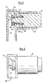
- the attachment connection between a dental prosthesis, which is itself not shown, and an anchoring part on the rest of the dentition, which is only shown in FIG. 6 in the form of a crown 1, consists of a slide-like male part 2, a female part 3, which forms a cavity 4 for positively receiving the male part 2, and both Attachment parts 2, 3 transversely to the direction of insertion (arrow 5) of the male part 2 into the locking part 6 connecting the female part 3.
- the locking pin 6 is axially displaceable in the female part 3 and carries a locking head 7 located in the female cavity 4 and widened transversely to the insertion direction with respect to the cross section of the pin.
- the locking pin 6 is adjustable with the locking head 7 in the direction of arrow 8 against the force of a spring 9 in the die cavity 4.
- a slot 10 which extends in the direction of insertion (arrow 5) of the male part 2 into the female part 3 and when the male part 2 is inserted into the female part 3 the locking pin 6 with the locking head 7 in the female cavity 4 against the spring 9 records.
- the slot 10 is open at the front edge of the male part 2 in the insertion direction (arrow 5) and ends opposite in a recess 11, into which the locking head 7 engages positively under the force of the spring 9 when the male part 1 is fully inserted into the female part 3.
- the die part 3 has a guide channel 12 which receives the locking pin 6 outside the die cavity 4 and is separated from the die cavity 4 by a transverse wall 13. In the transverse wall 13 there is an opening 14 for the passage of the locking pin 6.
- a guide member 15 which is fixed with the locking pin, namely one-piece with it in the exemplary embodiment, is displaceably guided. Between this guide member 15 and the transverse wall 13, the spring 9 is supported in the form of a helical compression spring surrounding the locking pin 6.
- the guide member 15 has a hollow ring cylinder 16 which receives the spring 9, so that it compresses the spring 9 can be adjusted up to the stop on the transverse wall 13 in the guide channel 12.
- the guide channel 12 is formed by a cylindrical sleeve 17 seated on the transverse wall 13.
- the guide member 15 has a corresponding cylindrical shape.
- the locking head 7 is screwed onto the locking pin 6 and is provided with an edge recess 18 for holding the locking head 7 in a torsion-proof manner in the die cavity 4 when it is screwed onto the locking pin 6.
- a tool is used which, according to FIGS. 7 to 9, is designed as a slide 19 which can be positively inserted into the die cavity 4.
- the slider 19 is provided with a mold recess 20 for receiving the locking head 7 and has a projection 21 on the recess edge, which engages in the edge recess 18 when the locking head 7 is inserted into the mold recess 20.
- the locking head 7 can be kept aligned in the die cavity 4 coaxially with the locking pin 6 when the locking pin 6 is screwed into the locking head 7.
- the locking head 7 is, moreover, rotationally symmetrical about the axis of the locking pin 6, so that the locking head 7 or the locking pin 6 does not need to be secured against rotation in the fully assembled attachment connection.
- the slot 10 provided in the male part 2 has in cross section a front slot part 10.1 of the width of only the locking pin diameter and a rear slot part 10.2 of the width of the locking head diameter.
- the front slot part 10.1 widens to the diameter of the locking head 7.
- the shoulder surfaces 22 formed in the transition between the front and rear slot parts 10.1, 10.2 on both sides of the slot 10 are inclined and thereby form oblique run-off surfaces for the locking head 7.
- the inclination of the shoulder surfaces 22 is such that the depth of the front slot part 10.1 at the open slot end, as seen in the adjustment direction (arrow 8) of the locking pin 6, is small or zero and increases towards the recess 11.
- the locking head 7 is pressed increasingly deeper into the die cavity against the force of the spring 9 via the shoulder surfaces 22 until it can snap into the recess 11 when the attachment connection is completely plugged together.
- the shoulder surfaces 22 also run obliquely, as seen in the slot cross section, so that the slot width widens like a wedge toward the rear slot part 10.2.
- the locking head 7 tapers correspondingly conically in the direction of the locking pin 6. As a result, the locking head 7 lies against the shoulder surfaces 22 in lines which are inclined to one another, which results in mutual self-centering and play-free alignment of the attachment parts 2, 3 under the force of the spring 9.
- the male part 2 is designed as a substantially rectangular plate and the female part 3 as a housing receiving this plate, which forms the partition 13 with one of its wide side walls. With the same wall, it carries the sleeve 17 on the outside.
- the housing is open on one of the narrow sides parallel to the direction of insertion at 23 for the connection of the male part 2 to the anchoring part 24.
- the anchoring part 24, in turn, is designed as a dovetail-shaped extension in one piece with the male part 2 and connected to the crown 1, which enables connection to the residual dentition, not shown.
Landscapes
- Health & Medical Sciences (AREA)
- Oral & Maxillofacial Surgery (AREA)
- Dentistry (AREA)
- Epidemiology (AREA)
- Life Sciences & Earth Sciences (AREA)
- Animal Behavior & Ethology (AREA)
- General Health & Medical Sciences (AREA)
- Public Health (AREA)
- Veterinary Medicine (AREA)
- Dental Prosthetics (AREA)
- Dental Tools And Instruments Or Auxiliary Dental Instruments (AREA)
- Component Parts Of Construction Machinery (AREA)
Claims (13)
Priority Applications (1)
| Application Number | Priority Date | Filing Date | Title |
|---|---|---|---|
| AT85113954T ATE40037T1 (de) | 1984-11-07 | 1985-11-02 | Geschiebeverbindung zwischen einer zahnprothese und einem verankerungsteil am restgebiss, sowie werkzeug zur montage der geschiebeverbindung. |
Applications Claiming Priority (2)
| Application Number | Priority Date | Filing Date | Title |
|---|---|---|---|
| DE19843440597 DE3440597A1 (de) | 1984-11-07 | 1984-11-07 | Geschiebeverbindung zwischen einer zahnprothese und einem verankerungsteil am restgebiss, sowie werkzeug zur montage der geschiebeverbindung |
| DE3440597 | 1984-11-07 |
Publications (2)
| Publication Number | Publication Date |
|---|---|
| EP0183086A1 EP0183086A1 (fr) | 1986-06-04 |
| EP0183086B1 true EP0183086B1 (fr) | 1989-01-18 |
Family
ID=6249675
Family Applications (1)
| Application Number | Title | Priority Date | Filing Date |
|---|---|---|---|
| EP85113954A Expired EP0183086B1 (fr) | 1984-11-07 | 1985-11-02 | Attache coulissante entre une prothèse dentaire et une pièce d'ancrage à la dentition restante, ainsi qu'outil pour le montage de l'attache |
Country Status (4)
| Country | Link |
|---|---|
| US (1) | US4659312A (fr) |
| EP (1) | EP0183086B1 (fr) |
| AT (1) | ATE40037T1 (fr) |
| DE (2) | DE3440597A1 (fr) |
Families Citing this family (4)
| Publication number | Priority date | Publication date | Assignee | Title |
|---|---|---|---|---|
| DE3720623A1 (de) * | 1987-05-14 | 1988-12-01 | Wolfgang Eisenmann | Anordnung zum verbinden einer zahnprothese mit einem restgebiss |
| DE8907997U1 (de) * | 1989-06-30 | 1990-11-08 | Obersat, Adam, 6750 Kaiserslautern | Vorrichtung zum Verriegeln eines herausnehmbaren Zahnprothesenteils an einem festsitzenden Zahnprothesenteil |
| BR9003271A (pt) * | 1990-07-09 | 1991-01-15 | Luiz Augusto De Siqueira | Dispositivo de precisao para a fixacao de protese dentaria removivel |
| CN105342712B (zh) * | 2015-12-03 | 2018-02-02 | 遂宁市中心医院 | 一种口腔种植体装置 |
Family Cites Families (8)
| Publication number | Priority date | Publication date | Assignee | Title |
|---|---|---|---|---|
| US2593287A (en) * | 1947-01-04 | 1952-04-15 | Fiorentini Alfredo | Arrangement for holding removable dental prothesis apparatus in the mouth |
| DE868047C (de) * | 1950-11-02 | 1953-05-28 | Guido Dr Zuccoli | Zahnprothese, insbesondere fuer den Einsatz kuenstlicher Endzaehne |
| DE7032068U (de) * | 1970-08-27 | 1970-11-26 | Degussa | Vorrichtung zur befestigung von zahnprothesen. |
| IT1112538B (it) * | 1979-05-09 | 1986-01-20 | Romagnoli Mario | Attacco per protesi dentale rimovibile,a struttura perfezionata |
| DE3201391C2 (de) * | 1982-01-19 | 1984-05-17 | Francesco 8014 Neubiberg Pedrazzini | Geschiebeverbindung, sowie Verfahren und Vorrichtungzur Herstellung einer Geschiebeverbindung |
| EP0085126A1 (fr) * | 1982-02-02 | 1983-08-10 | 3D -Dental Dinamic Diffusion | Dispositif de fixation amorti pour prothèses amovibles |
| DE8206064U1 (de) * | 1982-03-05 | 1983-02-03 | Rademacher, Bernd, 5800 Hagen | Vorrichtung zur loesbaren befestigung einer zahntechnischen teilprothese an kronen od.dgl. |
| DE8321205U1 (de) * | 1983-07-22 | 1983-12-15 | Rath, Elmar, 7513 Stutensee | Kupplungsbausatz zum festlegen eines herausnehmbaren zahnersatzes |
-
1984
- 1984-11-07 DE DE19843440597 patent/DE3440597A1/de not_active Withdrawn
-
1985
- 1985-11-02 EP EP85113954A patent/EP0183086B1/fr not_active Expired
- 1985-11-02 DE DE8585113954T patent/DE3567571D1/de not_active Expired
- 1985-11-02 AT AT85113954T patent/ATE40037T1/de not_active IP Right Cessation
- 1985-11-06 US US06/795,617 patent/US4659312A/en not_active Expired - Fee Related
Also Published As
| Publication number | Publication date |
|---|---|
| US4659312A (en) | 1987-04-21 |
| DE3567571D1 (en) | 1989-02-23 |
| EP0183086A1 (fr) | 1986-06-04 |
| DE3440597A1 (de) | 1986-05-15 |
| ATE40037T1 (de) | 1989-02-15 |
Similar Documents
| Publication | Publication Date | Title |
|---|---|---|
| DE69121207T2 (de) | Verbesserte dentale befestigungsstruktur | |
| DE4035581C2 (fr) | ||
| DE3406448A1 (de) | Buchsenteil einer kupplung zur befestigung von zahnprothesen im mund | |
| DE8427153U1 (de) | Druckmindervorrichtung für eine Rohr- oder Schlauchleitungs-Schnellkupplung | |
| DE2253904A1 (de) | Zahnaerztliches handstueck | |
| DE3203665C2 (fr) | ||
| EP0183086B1 (fr) | Attache coulissante entre une prothèse dentaire et une pièce d'ancrage à la dentition restante, ainsi qu'outil pour le montage de l'attache | |
| DE10229649A1 (de) | Medizinisches oder dentalmedizinisches Handstück mit einer Drucktaste zum Lösen eines Werkzeugs | |
| DE4041202C2 (de) | Geschiebe zur Fixierung einer abnehmbaren Zahnprothese | |
| DE3504638C1 (de) | Vorrichtung zur lösbaren Befestigung einer zahntechnischen Teilprothese an Kronen oder anderen restgebißseitigen Gegenstücken | |
| DE4425605A1 (de) | Riegelvorrichtung zur Befestigung künstlicher Zahnelemente an Restgebißteilen | |
| DE9207562U1 (de) | Intracoronales, T-förmiges Geschiebe | |
| DE102017007560B3 (de) | Verbindungselement zur lösbaren Befestigung eines herausnehmbaren Zahnersatzes an einem festsitzenden Zahnersatz, wie Zahnkronen, Teleskopkronen und Stegen, auf natürlichen Zähnen oder Zahnimplantaten; Verfahren zur lösbaren Befestigung eines herausnehmbaren Zahnersatzes an einem festsitzenden Zahnersatz, wie Zahnkronen, Teleskopkronen und Stegen, auf natürlichen Zähnen oder Zahnimplantaten | |
| DE3612011C1 (de) | Dentaltechnisches Geschiebe | |
| DE8517417U1 (de) | Geschiebe für klammerlose Zahnprothesen | |
| DE4218390A1 (de) | Intracoronales, t-foermiges geschiebe | |
| DE3421970A1 (de) | Vorrichtung zum befestigen eines abnehmbaren zahnprothesenteiles | |
| DE3111295A1 (de) | "wendbare spritzduese" | |
| DE69525131T2 (de) | Geschiebe für entfernbare zahnärztliche Prothese | |
| DE10011958C2 (de) | Dentalgeschiebe | |
| DE10011957C2 (de) | Anordnung zur lösbaren Fixierung eines Zahnersatzes an einem Restzahngebiss | |
| DE8321205U1 (de) | Kupplungsbausatz zum festlegen eines herausnehmbaren zahnersatzes | |
| DE9307788U1 (de) | Vorrichtung zum Befestigen eines abnehmbaren Zahnprothesenteils an einem festsitzenden Zahnprothesenteil | |
| DE29502302U1 (de) | Haltekonstruktion für Zahnprothesen | |
| DE10138394A1 (de) | Medizinisches Instrument |
Legal Events
| Date | Code | Title | Description |
|---|---|---|---|
| PUAI | Public reference made under article 153(3) epc to a published international application that has entered the european phase |
Free format text: ORIGINAL CODE: 0009012 |
|
| AK | Designated contracting states |
Kind code of ref document: A1 Designated state(s): AT BE CH DE FR IT LI LU NL |
|
| 17P | Request for examination filed |
Effective date: 19860911 |
|
| 17Q | First examination report despatched |
Effective date: 19871201 |
|
| GRAA | (expected) grant |
Free format text: ORIGINAL CODE: 0009210 |
|
| AK | Designated contracting states |
Kind code of ref document: B1 Designated state(s): AT BE CH DE FR IT LI LU NL |
|
| REF | Corresponds to: |
Ref document number: 40037 Country of ref document: AT Date of ref document: 19890215 Kind code of ref document: T |
|
| REF | Corresponds to: |
Ref document number: 3567571 Country of ref document: DE Date of ref document: 19890223 |
|
| ET | Fr: translation filed | ||
| ITF | It: translation for a ep patent filed | ||
| PLBE | No opposition filed within time limit |
Free format text: ORIGINAL CODE: 0009261 |
|
| STAA | Information on the status of an ep patent application or granted ep patent |
Free format text: STATUS: NO OPPOSITION FILED WITHIN TIME LIMIT |
|
| 26N | No opposition filed | ||
| ITTA | It: last paid annual fee | ||
| EPTA | Lu: last paid annual fee | ||
| PGFP | Annual fee paid to national office [announced via postgrant information from national office to epo] |
Ref country code: LU Payment date: 19951001 Year of fee payment: 11 |
|
| PGFP | Annual fee paid to national office [announced via postgrant information from national office to epo] |
Ref country code: CH Payment date: 19951005 Year of fee payment: 11 |
|
| PGFP | Annual fee paid to national office [announced via postgrant information from national office to epo] |
Ref country code: FR Payment date: 19951114 Year of fee payment: 11 |
|
| PGFP | Annual fee paid to national office [announced via postgrant information from national office to epo] |
Ref country code: BE Payment date: 19951116 Year of fee payment: 11 |
|
| PGFP | Annual fee paid to national office [announced via postgrant information from national office to epo] |
Ref country code: NL Payment date: 19951128 Year of fee payment: 11 |
|
| PGFP | Annual fee paid to national office [announced via postgrant information from national office to epo] |
Ref country code: AT Payment date: 19951130 Year of fee payment: 11 |
|
| PG25 | Lapsed in a contracting state [announced via postgrant information from national office to epo] |
Ref country code: LU Free format text: LAPSE BECAUSE OF NON-PAYMENT OF DUE FEES Effective date: 19961102 Ref country code: AT Effective date: 19961102 |
|
| PG25 | Lapsed in a contracting state [announced via postgrant information from national office to epo] |
Ref country code: LI Effective date: 19961130 Ref country code: CH Effective date: 19961130 Ref country code: BE Effective date: 19961130 |
|
| BERE | Be: lapsed |
Owner name: BADEMIS JOHANNIS Effective date: 19961130 |
|
| PG25 | Lapsed in a contracting state [announced via postgrant information from national office to epo] |
Ref country code: NL Effective date: 19970601 |
|
| REG | Reference to a national code |
Ref country code: CH Ref legal event code: PL |
|
| PG25 | Lapsed in a contracting state [announced via postgrant information from national office to epo] |
Ref country code: FR Effective date: 19970731 |
|
| NLV4 | Nl: lapsed or anulled due to non-payment of the annual fee |
Effective date: 19970601 |
|
| REG | Reference to a national code |
Ref country code: FR Ref legal event code: ST |
|
| PGFP | Annual fee paid to national office [announced via postgrant information from national office to epo] |
Ref country code: DE Payment date: 20040113 Year of fee payment: 19 |
|
| PG25 | Lapsed in a contracting state [announced via postgrant information from national office to epo] |
Ref country code: DE Free format text: LAPSE BECAUSE OF NON-PAYMENT OF DUE FEES Effective date: 20050601 |