EP0183202A1 - Translator device for plants handling rubberized fabric strips - Google Patents
Translator device for plants handling rubberized fabric strips Download PDFInfo
- Publication number
- EP0183202A1 EP0183202A1 EP85114843A EP85114843A EP0183202A1 EP 0183202 A1 EP0183202 A1 EP 0183202A1 EP 85114843 A EP85114843 A EP 85114843A EP 85114843 A EP85114843 A EP 85114843A EP 0183202 A1 EP0183202 A1 EP 0183202A1
- Authority
- EP
- European Patent Office
- Prior art keywords
- arm
- fabric
- strips
- translator
- needles
- Prior art date
- Legal status (The legal status is an assumption and is not a legal conclusion. Google has not performed a legal analysis and makes no representation as to the accuracy of the status listed.)
- Withdrawn
Links
- 239000004744 fabric Substances 0.000 title claims abstract description 35
- 230000007246 mechanism Effects 0.000 claims description 3
- 230000003014 reinforcing effect Effects 0.000 abstract description 2
- 230000008878 coupling Effects 0.000 description 3
- 238000010168 coupling process Methods 0.000 description 3
- 238000005859 coupling reaction Methods 0.000 description 3
- 230000000903 blocking effect Effects 0.000 description 2
- 238000004519 manufacturing process Methods 0.000 description 2
- 239000013536 elastomeric material Substances 0.000 description 1
- 230000001788 irregular Effects 0.000 description 1
- 230000003534 oscillatory effect Effects 0.000 description 1
Images

Classifications
-
- B—PERFORMING OPERATIONS; TRANSPORTING
- B65—CONVEYING; PACKING; STORING; HANDLING THIN OR FILAMENTARY MATERIAL
- B65H—HANDLING THIN OR FILAMENTARY MATERIAL, e.g. SHEETS, WEBS, CABLES
- B65H5/00—Feeding articles separated from piles; Feeding articles to machines
- B65H5/16—Feeding articles separated from piles; Feeding articles to machines by pusher, needles, friction, or like devices adapted to feed single articles along a surface or table
-
- B—PERFORMING OPERATIONS; TRANSPORTING
- B65—CONVEYING; PACKING; STORING; HANDLING THIN OR FILAMENTARY MATERIAL
- B65H—HANDLING THIN OR FILAMENTARY MATERIAL, e.g. SHEETS, WEBS, CABLES
- B65H39/00—Associating, collating, or gathering articles or webs
- B65H39/14—Associating sheets with webs
Definitions
- the present invention refers to a translator-device used in plants for handling rubberized fabrics and, more specifically for fabric-cord strips.
- the piecing-machines used for jointing the cord-fabric strips are machines which produce cord-fabric tapes having transversal cords, starting with cord-fabric pieces having cords parallel to the lateral edges of the piece.
- the machines in question comprise a first motor-driven support - on which the cord-fabric strips are formed by cutting them off from a cord-fabric piece having cords that are parallel to the lateral edges of the piece; as well as a second motor-driven support - downstream of the first one upon which - after being transferred from a translator-device, these strips are caused to advance, in the oblique direction with respect to the reinforcing cords, towards a device that connects them, in series, to one another.
- the passage of the fabric-cord strips - from the first to the second support is carried-out through the means of a translator-device which - after having grasped each fabric strip that rests upon the first motor-driven support, drags it over to the the second motor-driven support.
- the known translator-devices presently used in plants for handling fabrics - and, in particular, in piecing machines, make use, for the jointing of the fabric-strips, of a plurality of sucking-discs borne by a mobile arm and connected to a pneumatic circuit.
- the sucking-discs are disposed on one edge of the fabric-strip. When they are depressurized, they result as being coupled with the fabric.
- the arm that bears the sucking-discs starts to shift and - in moving from the first to the second support, drags the fabric-strip along with it.
- the sucking-discs cease to be depressurized - and hence, by releasing their hold of the fabric-strip, they leave it free upon the second support.
- the arm bearing the sucking-discs returns, once more, to its starting position for grasping still another rubberized-fabric strip - and for carrying-out with it the previously described operations; whereas the fabric-strip that has just been transferred onto the second motor-driven support, is caused to advance from there till it reaches a device for effectuating the jointing - between the just-arrived strip and the end of the tape that is already comprised in the jointed-strip.
- a second drawback consists of the poor precision in the orientation of the fabric-strips on the second motor-driven support, due to the friction encountered - while being transferred from the first to the second support and the scant effectiveness of the coupling ensured by the sucking-discs, permitting relative slippings to occur between the latter and the fabric-strips during their transferring.
- a poor precision in orientation of the rubberized-fabric strips on the second motor-driven support causes a variation in the angle of the cords with respect to the longitudinal direction of the tape to be produced - and hence, the need for having a greater surmounting of the edges of the strips themselves - as with respect to what is theoretically required between the strips - during their reciprocal coupling.
- the tapes which are obtained through the known piecing-machines result as having irregular characteristics and non-uniform joints - i.e. with originating drawbacks during their usage - for example, in the manufacture of tyres and such-like.
- a third drawback results from the fact of the sucking-discs causing permanent undulations at the edges of the rubberized fabric which they grip - since the elastomeric material of the latter is non-vulcanized and hence, it is easily deformable in a permanent way.
- the undulations caused by the sucking-discs can be the cause of imprecisions had in the operations of jointing the diverse strips, as carried-out on the second motor-driven support.
- a final drawback is the slowness with which the transferring is carried-out of the fabric-strip - from one motor-driven support to the other. This slowness is owed to the fact that for effectuating the depressurizing in the sucking-discs and their successive pressurizing, it is necessary to place the entire pneumatic circuit connected with them, under said conditions.
- the aim of the present invention is a translator-device that obviates all the above-given drawbacks of the already known devices, with also conferring a greater reliability to the plants that handle fabrics - where said translator-device is used, and also to the products obtained with them.
- What forms the object of the present invention is a translator-device for plants that handle rubberized fabrics, which is apt for transferring the said fabrics from a first tc a second support, the said translator-device comprising a mobile arm - mounted on a plane above the two supports and provided with removable grasping-means, that is disposed at one edge of said fabric, characterized by the fact that said removable grasping-means comprise:
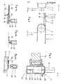
- the plant comprises a first motor-driven support 1 and a second motor-driven support 2.
- the working-surfaces of the motor-driven supports 1 and 2 are coplanar.
- the motor-driven support 1 is comprised by a plurality of conveyor-belts 3 that are parallel to one another and mounted between two rollers 4 supported by a casing 5.
- the motor-driven support 2 is formed by a plurality of conveyor-belts 6 mounted between two rollers 7 - (only one is shown in FIG. 1) that, in their turn, are supported by a framework 8.
- a cutting-device 9 (whose details will be described further on in the text) and, on the motor-driven support 2 there is present a per se known device 10, through which the jointing is carried-out between the various strips of rubberized-fabric.
- a translator-device is interposed between the motor-driven supports 1 and 2.
- the translator-device comprises an arm 11 - whose details (that will be described further on inthe text) are shown in FIG. 3, supported upon a casing 12 to which there is connected a cylinder-piston system 13 that is apt for imparting to the casing - and to the arm 11 supported by it, an alternating motion in a plane parallel to the common plane where lie the working-surfaces of the motor driven supports 1 and 2.
- the arm 11 is hinged - at its extremity 14, to the casing 12 and, in an intermediate position, said arm 11 is fixed to said casing 12 by a cylinder-piston system 15 - which is apt both, for imparting an alternating oscillatory motion to the arm 11 - with respect to the extremity 14, as well as for adjusting the inclination of the arm 11 - with respect to the casing 12.
- the plant moreover, comprises a slab 16 (seen in FIG. 2) underlying the arm 11 and interposed in the space between the first and the second motor-driven supports.
- the surface 17 of slab 16 is coplanar with the working-surfaces of the motor-driven supports 1 and 2 and inside them are present grooves 18 - whose function will be described further on in the text.
- the arm 11 has a structure (as seen in FIG. 3) that will be described herebelow.
- the arm 11 comprises a U-section structural-shape 19 - that, in correspondence of its own base 20, is provided with a plurality of holes 21 which are aligned one with the other.
- a rigid rod 22 - that bears on its surface a plurality of needles 24, which engage with the holes 21 of the U-section structural-shape 19.
- a lid 26 which shuts the hollow cavity of the U-section structural-shape 19 and also supports the cylinder-piston systems 27.
- the cylinder-piston systems 27 are rigidly connected to the rod 22 and impart to the latter an alternating motion, with three stopping-positions, guided by the wings of the U-section structural-shape 19.
- the needles 24 of the translator-device are housed in the characteristic above-described cavities 18 - which are present in the slab 16 (see FIG. 2).
- the cutting-means 9, comprise a blade, that is transversally slidable in a casing 28 disposed transversally to the motor-driven support 1.
- the casing 28 is supported by a framework 29 - which is shiftable along the casing 5 of the first motor-driven support - and with removable means being foreseen between the framework and the casing. Moreover, the casing 28 is hinged at 30 to the framework 29 - and means for blocking the hinging 30, are provided.
- the translator-device and the piecing-machine - for the rubberized-fabric strips, to which it is applied, are moreover, provided with means of the per se known type, for coordinating the movements of the various mechanisms comprising them - and which hence, will not be described here, as anyone skilled in the art is quite able to determine them from the description given herebelow, of the functioning of the device according to the invention.
- the width is pre-established of the fabric-cord tape that must be produced and the inclination which the transversal cords must have in said tape - with respect to the edges of the tape itself.
- a further preliminary adjustment consists in disposing the rod 11 - of the translator-device, parallelly to the casing 28 and with causing it to rotate about the hinge 14 present at its extremity, through an adjustment in the length of the cylindrical-piston system 15.
- the motor-driven support 1 starts operating and, in particular, it puts into motion the conveyor-belts 3 that comprise it - with thus causing the rubberized-fabric piece 31 to advance till it takes the edge 32 into the slab 16 (FIG. 4a) underlying the rod 11 of the translator-device.
- the device 9 When the edge 32 has reached this position - as signalized, for example, by a photo-electric cell, the device 9 causes the piece 31' to be cut - with thus originating a fabric-strip 33 (shown with a dot-and-dash line in FIG. 1) and, after this, the translator-device starts operating.
- the first operation carried-out by the translator-device is to grasp the edge 32 of the fabric-strip 33 that is found under the arm 11.
- the cylinder-piston system 27 comes into function through the arm 11 - which causes the needles 24 to exit from the U-section structural-shape 19 and to pierce the edge of the fabric-strip 33 to be finally housed in the opening 18 of slab 16.
- the cylinder-piston system 13 starts to function, with causing the transferring of the arm 11 - and so also the cylinder-piston system 15, with causing a rotation of said arm 11 about its own extremity 14.
- the rubberized fabric-strip which the translator-device has disposed on the second motor-driven support 2 is shifted upon it towards the device 10 - that will provide for the jointing of this rubberized fabric-strip to the other, previously joined strips - for, in this way, originating a rubberized-fabric tape containing transversal cords.
- the first motor-driven support 1 causes the rubberized fabric piece 31 to advance once more - for originating another rubberized fabric-strip 33.
- the cylinder-piston systems 13 and 15 begin to operate once again - with causing the arm 11 to return to its starting position.
- the translator-device - is apt for grasping the strips by means of the needles - that cause a perforation in the edge of these strips, there is guaranteed a sure fixing between said elements - which is not at all influenceable by the frictions that are encountered by the strips when taken from the first to the second support.
- this translator-device has been described in connection with a plant for the production and the jointing of rubberized fabric-strips - with only pointing out, through referring to a practical case, all its constructive and functioning characteristics.
- said translator-device has absolutely not to be taken as limited to this specific plant, but that it can also be used in any other whatsoever plants handling rubberized fabrics - such as, for example, in devices used for feeding the semifinished fabrics to the building-drums for tyre carcasses.
Landscapes
- Engineering & Computer Science (AREA)
- Mechanical Engineering (AREA)
- Advancing Webs (AREA)
- Treatment Of Fiber Materials (AREA)
Applications Claiming Priority (2)
| Application Number | Priority Date | Filing Date | Title |
|---|---|---|---|
| IT23848/84A IT1178673B (it) | 1984-11-30 | 1984-11-30 | Dispositivo traslatore per impianti di manipolazione di spezzioni di tessuto gommato |
| IT2384884 | 1984-11-30 |
Publications (1)
| Publication Number | Publication Date |
|---|---|
| EP0183202A1 true EP0183202A1 (en) | 1986-06-04 |
Family
ID=11210395
Family Applications (1)
| Application Number | Title | Priority Date | Filing Date |
|---|---|---|---|
| EP85114843A Withdrawn EP0183202A1 (en) | 1984-11-30 | 1985-11-22 | Translator device for plants handling rubberized fabric strips |
Country Status (4)
| Country | Link |
|---|---|
| EP (1) | EP0183202A1 (it) |
| JP (1) | JPS61162450A (it) |
| BR (1) | BR8506189A (it) |
| IT (1) | IT1178673B (it) |
Cited By (1)
| Publication number | Priority date | Publication date | Assignee | Title |
|---|---|---|---|---|
| DE8811030U1 (de) * | 1988-09-01 | 1988-10-20 | Spühl (Deutschland) GmbH, 6800 Mannheim | Nadelgreifer |
Citations (2)
| Publication number | Priority date | Publication date | Assignee | Title |
|---|---|---|---|---|
| DE2839257A1 (de) * | 1977-09-22 | 1979-04-05 | Cluett Peabody & Co Inc | Vorrichtung zum aufnehmen und ablegen eines duennen werkstoffes |
| JPS58197139A (ja) * | 1982-05-14 | 1983-11-16 | Yokohama Rubber Co Ltd:The | シ−ト状物の搬送装置 |
-
1984
- 1984-11-30 IT IT23848/84A patent/IT1178673B/it active
-
1985
- 1985-11-22 EP EP85114843A patent/EP0183202A1/en not_active Withdrawn
- 1985-11-29 BR BR8506189A patent/BR8506189A/pt unknown
- 1985-11-29 JP JP60269234A patent/JPS61162450A/ja active Pending
Patent Citations (2)
| Publication number | Priority date | Publication date | Assignee | Title |
|---|---|---|---|---|
| DE2839257A1 (de) * | 1977-09-22 | 1979-04-05 | Cluett Peabody & Co Inc | Vorrichtung zum aufnehmen und ablegen eines duennen werkstoffes |
| JPS58197139A (ja) * | 1982-05-14 | 1983-11-16 | Yokohama Rubber Co Ltd:The | シ−ト状物の搬送装置 |
Non-Patent Citations (1)
| Title |
|---|
| PATENT ABSTRACTS OF JAPAN, vol. 8, no. 40 (M-278)[1477], 21th February 1984; & JP - A - 58 197 139 (YOKOHAMA GOMU K.K.) 16-11-1983 * |
Cited By (1)
| Publication number | Priority date | Publication date | Assignee | Title |
|---|---|---|---|---|
| DE8811030U1 (de) * | 1988-09-01 | 1988-10-20 | Spühl (Deutschland) GmbH, 6800 Mannheim | Nadelgreifer |
Also Published As
| Publication number | Publication date |
|---|---|
| IT8423848A1 (it) | 1986-05-30 |
| IT1178673B (it) | 1987-09-16 |
| JPS61162450A (ja) | 1986-07-23 |
| IT8423848A0 (it) | 1984-11-30 |
| BR8506189A (pt) | 1986-06-17 |
Similar Documents
| Publication | Publication Date | Title |
|---|---|---|
| JP4383573B2 (ja) | 仮とじ本、雑誌又は書籍のような印刷物の自動断裁用断裁機 | |
| JP3699218B2 (ja) | サックの製造時に底を形成する目的で、連続的にクロス搬送されるチューブセクションを引き開く装置 | |
| JPS6017701B2 (ja) | シ−トの打抜き方法及び装置 | |
| CN209398685U (zh) | 一种胶条贴附机 | |
| US4109842A (en) | Sheet stripping device | |
| KR20020022574A (ko) | 일반적으로 플레이트, 특히 유리판의 에지를 가공하는기계의 에지 연삭기 | |
| US5246533A (en) | Apparatus for press-bonding tape onto edges of workpiece | |
| EP0183202A1 (en) | Translator device for plants handling rubberized fabric strips | |
| JP4733826B2 (ja) | 圧延鋼板を幅方向分割する高速シャー | |
| KR880006095A (ko) | 시트 절단-전송 시스템 | |
| EP0004290B1 (en) | Sheet feed | |
| CN119526829A (zh) | 扁绳输送装置及袋体成型机 | |
| US2553473A (en) | Belt-aligning apparatus | |
| US3932259A (en) | Method and apparatus for the manufacture of sheets for holding postage stamps or the like | |
| US4358336A (en) | Device for applying tapes (tear-tapes) or the like to a web of material | |
| JPH0260479B2 (it) | ||
| JP3281212B2 (ja) | 弾性を有するシート状長尺物の切断方法およびその切断装置 | |
| KR950011934B1 (ko) | 용지구동형 자동제도기 | |
| JP3009954B2 (ja) | シート材料裁断システムのコンベア装置 | |
| JP3152369B2 (ja) | 帯状部材の切断方法および切断装置 | |
| JP3056792U (ja) | 長尺シート加工装置 | |
| US20070157777A1 (en) | Device and method for preparing a piece of adhesive tape of desired length from a reel | |
| CN219151896U (zh) | 一种激光打标机的控制装置 | |
| CN223265836U (zh) | 一种假皮面料切边机的切边机构 | |
| CN211395150U (zh) | 一种缎带加工用剪裁装置 |
Legal Events
| Date | Code | Title | Description |
|---|---|---|---|
| PUAI | Public reference made under article 153(3) epc to a published international application that has entered the european phase |
Free format text: ORIGINAL CODE: 0009012 |
|
| AK | Designated contracting states |
Kind code of ref document: A1 Designated state(s): DE FR GB |
|
| STAA | Information on the status of an ep patent application or granted ep patent |
Free format text: STATUS: THE APPLICATION IS DEEMED TO BE WITHDRAWN |
|
| 18D | Application deemed to be withdrawn |
Effective date: 19870205 |
|
| RIN1 | Information on inventor provided before grant (corrected) |
Inventor name: CAIRATI, FERDINANDO |