EP0183206B1 - Régulateur de vitre coulissant - Google Patents
Régulateur de vitre coulissant Download PDFInfo
- Publication number
- EP0183206B1 EP0183206B1 EP85114862A EP85114862A EP0183206B1 EP 0183206 B1 EP0183206 B1 EP 0183206B1 EP 85114862 A EP85114862 A EP 85114862A EP 85114862 A EP85114862 A EP 85114862A EP 0183206 B1 EP0183206 B1 EP 0183206B1
- Authority
- EP
- European Patent Office
- Prior art keywords
- roller
- window regulator
- set forth
- side wall
- support brackets
- Prior art date
- Legal status (The legal status is an assumption and is not a legal conclusion. Google has not performed a legal analysis and makes no representation as to the accuracy of the status listed.)
- Expired
Links
Images


Classifications
-
- B—PERFORMING OPERATIONS; TRANSPORTING
- B60—VEHICLES IN GENERAL
- B60J—WINDOWS, WINDSCREENS, NON-FIXED ROOFS, DOORS, OR SIMILAR DEVICES FOR VEHICLES; REMOVABLE EXTERNAL PROTECTIVE COVERINGS SPECIALLY ADAPTED FOR VEHICLES
- B60J1/00—Windows; Windscreens; Accessories therefor
- B60J1/08—Windows; Windscreens; Accessories therefor arranged at vehicle sides
- B60J1/12—Windows; Windscreens; Accessories therefor arranged at vehicle sides adjustable
- B60J1/16—Windows; Windscreens; Accessories therefor arranged at vehicle sides adjustable slidable
- B60J1/17—Windows; Windscreens; Accessories therefor arranged at vehicle sides adjustable slidable vertically
Definitions
- the invention relates to a window regulator comprising the features as indicated in the precharacterising part of claim 1.
- Such a window regulator as disclosed in US-A-1 928 056 comprises U-shaped guide rails having planar side walls, each are in engagement with two pairs of rollers.
- Spring means are disposed for biasing one pair of rollers against one planar side wall and for biasing the other pair of rollers against the other planar side wall.
- further rollers biased by spring means are provided.
- the inventive window regulator comprises a pair of stationary guide rails and a pair of roller units movably engaged with the guide rails.
- Each of the guide rails is U-shaped in cross section and has first and second parallel side walls.
- the first side wall is formed with a longitudinal groove of a V-shaped cross section and the second side wall is planar.
- Each of the roller units includes a first roller in rolling contact with the first side wall and a second roller in rolling contact with the second side wall.
- Such the inventive window regulator provides a smoothly movement, wherein production tolerances are compensated in a simple manner.
- a window regulator is generally indicated by the reference numeral 10 and used for raising and lowering a door glass or window pane 40 of an automotive vehicle door 41.
- the window regulator 10 includes a pair of guide rails 20, 20 disposed nearly vertically or disposed to elongate in the direction of movement of the window pane 40 and joined together by means of a beam or connecting plate 42 which is secured to the door 41.
- the window regulator 10 further includes a cable 11 having a portion extending alongside one of the guide rails 20, 20 and placed around a pair of guide pulleys 12, 12 and a winding drum 13a of a drive unit 13.
- the drive unit 13 consists of a winding drum 13a and a drive motor 13b.
- the guide rails 20, 20 are U-shaped in cross section and includes a pair of side walls 21, 23, one 21 of which is formed with a longitudinal groove 22 of a V-shaped cross section and the other 23 is formed to be flat or planar.
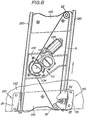
- each roller unit 30 consists of a carrier plate assembly 31 secured to the window pane 40 and having a pair of elongated support brackets 31 a, 31 b parallel to the guide rails 20, 20, a pair of convexly surfaced guide rollers 32, 32 having a convex outer circumferential periphery and rotatably supported on the support brackets 31a, 31b at the locations adjacent the upper and lower ends thereof, and a flat surfaced roller 33 having a flat outer circumferential periphery and rotatably supported on the supprt brackets 31a, 31 b at the location between the convexly surfaced rollers 32, 32.
- the support bracket 31 a is L-shaped in cross section, while the support bracket 31b is in the form of a flat or planar elongated plate.
- the support brackets 31a and 31b are integrally connected to each other by a pair of shafts 31c, 31d which extend therebetween and secured to same at the opposite ends thereof.
- the lower convexly surfaced roller 32 is rotatably mounted on the shaft 31c, while the upper convexly surfaced roller 32 is rotatably mounted on a shaft 31e which extends between the support brackets 31a, 31 and mounted on same at the opposite ends thereof.
- the convexly surfaced roller 32 is engaged in or in rolling contact with the V-shaped groove 22 of the side wall 21, while the flat surfaced roller 33 is in rolling contact with the side wall 23.
- the flat surfaced roller 33 is rotatably mounted on an eccentric portion 36 of a shaft 34 which is in turn rotatably mounted at the opposite ends thereof on the support brackets 31 a, 31b b of the carrier plate assembly 31.
- a pivotal lever 35 is mounted at an end thereof on the eccentric portion 36 of the shaft 34 to rotate together therewith and connected at the other end thereof to an end of a coil spring 37 placed around the shaft 31 d.
- the other end of the coil spring 37 is abuttingly engaged with a stopper 31f integrally provided to the support bracket 31 b in such a manner as to be preloaded to urge the pivotal lever 35 in the clockwise direction in Fig. 6, i.e., to urge the flat surfaced roller 33 toward the flat surfaced side wall 23 of the guide rail 20.
- one of the roller units 30, 30 is located more forward of the vehicle than the other, and the window pane 40 is mounted at the forward and rearward lower end portions thereof on the support brackets 31a, 31a of the forward and rearward roller units 30, 30, respectively.
- a connecting plate 14 is integrally connected as best seen from Fig. 7.
- the connecting plate 14 has a connecting end 15 extended toward the cable 11 to connect thereto the opposite ends 11 a, 11 b of the cable 11 by a suitable fastening means such as trunnion pins 15a, 15b.
- the roller units 30, 30 Upon the upward and downward movements of the window pane 40, the roller units 30, 30 are caused to move upwardly and downwardly being guided by the guide rails 20, 20.
- the flat surfaced rollers 33, 33 are urged against the side walls 23, 23 under the bias of the springs 37, 37, the convexly surfaced rollers 32, 32 are urged away from the fiat surfaced rollers 33,33 to fittingly engage in the grooves 22, 22.
- the pivotal lever 35 is mounted on the eccentric portion 36 of the shaft 34 to rotate together therewith and constructed and arranged so that the bias of the spring 37 to be applied to the flat surfaced roller 33 is amplified by the effect of leverage, thus making it possible to efficiently transmit the bias of the spring 37 to the flat surfaced roller 33. Accordingly, with the small-sized spring 37, the roller units 30, 30 are assuredly engaged with the guide rails 20, 20 without any play therebetween even if the grooves 22, 22 of the side walls 23, 23 have any dimensional errors in the direction transversal to the side walls 23, 23.
- the groove 22 is formed in one side wall 21 only and the other side wall 23 is formed to be planar, whereby all of the rollers 32,33 can fittingly engage the side walls 21, 23 without any play therebetween even if the groove 22 has any dimensional errors in the direction parallel to the side wall 23.
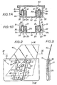
- Fig. 1A shows the roller units 30, 30 and the guide rails 20, 20 in an installed or assembled state in which the convexly surfaced rollers 32, 32 are aligned with the grooves 22, 22, i.e., correctly received in the grooves 22, 22.
- Fig. 1 B shows another installed or assembled state in which one convexly surfaced roller 32 is misaligned with the groove 22, i.e., incorrectly received in the groove 22.
- the rollers 32, 33 are allowed to go nearer to each other by the resilience of the spring 37, thus preventing the rollers 32, 33 from sticking to the guide rails 20, 20.
- FIG. 8 through 12 Another embodiment is shown in Figs. 8 through 12, in which elements like or corresponding to those in the previous embodiment are denoted by adding 100 to their identifying numerals.
- This embodiment features that the flat surfaced roller 133 is made of metal such as iron, steel, etc. while the convexly surfaced rollers 132, 132 are made of a hard synthetic resinous material having a predetermined resiliency such as acetal resins. More specifically, the roller 133 made of metal is formed from a ball bearing consisting of an outer ring 133a, an inner ring 133b mounted on the eccentric portion 136 of the shaft 134, and a plurality of balls 133c confined between the outer and inner rings 133a, 133b.
- the outer ring 133a is in rolling contact with the side wall 123 under the bias of the spring 137.
- the rollers 132,132 made of a synthetic resinous material is engaged in or in rolling contact with the grooves 122,122 formed in the side walls 121, 121. Except for the above structure, this embodiment is substantially similar to the previous embodiment.
- the flat surfaced roller 133 is made of metal while the convexly surfaced rollers 132, 132 are made of a synthetic resinous material. This is quite effective for reducing the resistance to movement of the roller unit 130 on the guide rail 120, whereby to make it possible for the window pane 140 to move more smoothly.
- rollers 132, 132 made of a synthetic resinous material are engaged with one side wall 121 of the guide rail 120 while the roller 133 made of metal is engaged with the other side wall 123. This is quite effective for attaining smooth movement of the window pane 140 for a long period of time since the roller 133 made of metal is assuredly and durably engaged with the guide rail 120 while the rollers 132, 132 made of a synthetic resinous material make soft and smooth the abutting engagement of the roller 133 with the guide rail 120.
- Figs. 8 through 12 can produce the above effect in addition to the same effect as the previous embodiment of Figs. 1 through 7.
Landscapes
- Engineering & Computer Science (AREA)
- Mechanical Engineering (AREA)
- Window Of Vehicle (AREA)
Claims (12)
Applications Claiming Priority (4)
| Application Number | Priority Date | Filing Date | Title |
|---|---|---|---|
| JP248491/84 | 1984-11-24 | ||
| JP24849184A JPS61126279A (ja) | 1984-11-24 | 1984-11-24 | 窓ガラスの昇降装置 |
| JP22891985A JPH075023B2 (ja) | 1985-10-16 | 1985-10-16 | 窓ガラス案内装置 |
| JP228919/85 | 1985-10-16 |
Publications (3)
| Publication Number | Publication Date |
|---|---|
| EP0183206A2 EP0183206A2 (fr) | 1986-06-04 |
| EP0183206A3 EP0183206A3 (en) | 1987-08-19 |
| EP0183206B1 true EP0183206B1 (fr) | 1989-10-25 |
Family
ID=26528535
Family Applications (1)
| Application Number | Title | Priority Date | Filing Date |
|---|---|---|---|
| EP85114862A Expired EP0183206B1 (fr) | 1984-11-24 | 1985-11-22 | Régulateur de vitre coulissant |
Country Status (3)
| Country | Link |
|---|---|
| US (1) | US4669222A (fr) |
| EP (1) | EP0183206B1 (fr) |
| DE (1) | DE3573906D1 (fr) |
Families Citing this family (12)
| Publication number | Priority date | Publication date | Assignee | Title |
|---|---|---|---|---|
| JPS61125916A (ja) * | 1984-11-24 | 1986-06-13 | Nissan Motor Co Ltd | 自動車用ウインドパネルの昇降装置 |
| DE3803118A1 (de) * | 1988-02-03 | 1989-08-17 | Porsche Ag | Fuehrungseinrichtung fuer eine in der hoehe verstellbare fensterscheibe |
| JPH02221580A (ja) * | 1989-02-22 | 1990-09-04 | Mazda Motor Corp | 車両のウインドレギュレータ |
| JPH03209042A (ja) * | 1990-01-08 | 1991-09-12 | Koito Mfg Co Ltd | 昇降装置 |
| DE10149106C2 (de) * | 2001-10-05 | 2003-11-20 | Audi Ag | Vorrichtung zum Führen einer beweglichen Fensterscheibe in einer Fahrzeugtür |
| KR100463152B1 (ko) | 2002-04-19 | 2004-12-23 | 현대자동차주식회사 | 자동차의 도어 글래스 승강장치 |
| US6922944B1 (en) * | 2003-05-05 | 2005-08-02 | Jackson Machine, Inc. | Powered access window for machinery |
| WO2006012746A1 (fr) * | 2004-08-06 | 2006-02-09 | Magna Closures Inc. | Regulateur de fenetre a rail unique en double guidage |
| US9050878B2 (en) * | 2012-04-12 | 2015-06-09 | Dura Global Technologies, Llc | Vehicle sliding door assembly |
| CN102992197B (zh) * | 2012-12-05 | 2015-11-18 | 宁夏电力公司检修公司 | 接地极极址盖板起重装置 |
| US20160032637A1 (en) * | 2014-08-01 | 2016-02-04 | A.P.A. Industries, Inc. | Car Window Regulator Using Rotational Bearing Pullies |
| US10676978B2 (en) | 2017-06-16 | 2020-06-09 | Todd A. Hohwart | Actuatable sliding panel assembly; retrofit kit and method for retrofitting a sliding panel for mechanically assisted movement between open and closed positions |
Family Cites Families (9)
| Publication number | Priority date | Publication date | Assignee | Title |
|---|---|---|---|---|
| US3125334A (en) * | 1964-03-17 | Window regulator | ||
| US1928056A (en) * | 1930-10-10 | 1933-09-26 | Excel Curtain Company | Automobile door and window construction |
| US1953355A (en) * | 1932-01-06 | 1934-04-03 | Excel Curtain Company | Sash and window construction for automobile door bodies |
| US2000561A (en) * | 1933-10-14 | 1935-05-07 | Murray Corp | Window support |
| US2379925A (en) * | 1941-04-04 | 1945-07-10 | Marvel Equipment Corp | Window guide |
| GB830723A (en) * | 1958-04-25 | 1960-03-16 | Standard Pressed Steel Co | Improvements in or relating to vehicle doors |
| GB1035980A (en) * | 1963-05-29 | 1966-07-13 | Bayerische Motoren Werke Ag | Improvements in or relating to sliding window pane mechanisms |
| US3640022A (en) * | 1969-10-29 | 1972-02-08 | Golde Gmbh H T | Window-guiding device |
| YU137274A (en) * | 1973-05-25 | 1982-02-25 | Hoerbiger Ventilwerke Ag | Improvement in an unloading valve for closed rooms |
-
1985
- 1985-11-21 US US06/799,870 patent/US4669222A/en not_active Expired - Lifetime
- 1985-11-22 EP EP85114862A patent/EP0183206B1/fr not_active Expired
- 1985-11-22 DE DE8585114862T patent/DE3573906D1/de not_active Expired
Also Published As
| Publication number | Publication date |
|---|---|
| EP0183206A3 (en) | 1987-08-19 |
| EP0183206A2 (fr) | 1986-06-04 |
| US4669222A (en) | 1987-06-02 |
| DE3573906D1 (en) | 1989-11-30 |
Similar Documents
| Publication | Publication Date | Title |
|---|---|---|
| US4669222A (en) | Window regulator | |
| US4691475A (en) | Window regulator | |
| CA1282097C (fr) | Guide-panneau pour vitre coulissante d'automobile | |
| US4712484A (en) | Conveyor arrangement | |
| EP0179467B1 (fr) | Dispositif de guidage pour une vitre de portière d'automobile | |
| EP1390284B1 (fr) | Dispositif de determination de la position d'une cabine d'ascenseur sur rails au moyen d'un porteur de code | |
| KR910014297A (ko) | 에스컬레이터 | |
| KR100315568B1 (ko) | 자동차용 윈도우 레귤레이터의 유격 조정장치 | |
| CA2444049A1 (fr) | Guide lineaire | |
| WO2003011732A1 (fr) | Systeme d'ascenseur dote d'un equipement permettant de determiner la position de la cabine | |
| US20030042080A1 (en) | Device for producing elevator shaft information | |
| DE102022101462A1 (de) | Zahnsprungschutzvorrichtung | |
| GB2368613A (en) | Window panel supporting structure of a window regulator | |
| US3643517A (en) | Power transmitting chain with floating bushing and method of manufacture | |
| KR910003134B1 (ko) | 경량형 선형볼베어링구조 | |
| CA2052573A1 (fr) | Rail-guide pour porte paliere coulissante | |
| EP0841281B1 (fr) | Mécanisme glissant de sécurité | |
| CA1182846A (fr) | Ressort antagoniste | |
| US4758211A (en) | V belt for power transmission | |
| US6857229B2 (en) | Door window lifting apparatus of a vehicle | |
| DE3411452A1 (de) | Foerdereinrichtung fuer werkstuecke bzw. werkstuecktraeger, insbesondere fuer eine montagemaschine | |
| DE3466731D1 (en) | Device for transforming a rotational movement into a translational movement | |
| US7152713B2 (en) | Door track for an elevator door system | |
| US5374127A (en) | Linear motion rolling guide unit | |
| US4680892A (en) | Device for guiding upward and downward movement of window pane of automotive vehicle door |
Legal Events
| Date | Code | Title | Description |
|---|---|---|---|
| PUAI | Public reference made under article 153(3) epc to a published international application that has entered the european phase |
Free format text: ORIGINAL CODE: 0009012 |
|
| 17P | Request for examination filed |
Effective date: 19851122 |
|
| AK | Designated contracting states |
Kind code of ref document: A2 Designated state(s): DE FR GB |
|
| RIN1 | Information on inventor provided before grant (corrected) |
Inventor name: KINOSHITA, TOMOTAKA Inventor name: UGAWA, SATORU Inventor name: NISHIJIMA, HIROTAKA Inventor name: UJIHARA, HIROSHI |
|
| RIN1 | Information on inventor provided before grant (corrected) |
Inventor name: OBUCHI, SATOSHI Inventor name: KINOSHITA, TOMOTAKA Inventor name: UGAWA, SATORU Inventor name: NISHIJIMA, HIROTAKA Inventor name: UJIHARA, HIROSHI |
|
| PUAL | Search report despatched |
Free format text: ORIGINAL CODE: 0009013 |
|
| AK | Designated contracting states |
Kind code of ref document: A3 Designated state(s): DE FR GB |
|
| 17Q | First examination report despatched |
Effective date: 19880427 |
|
| GRAA | (expected) grant |
Free format text: ORIGINAL CODE: 0009210 |
|
| AK | Designated contracting states |
Kind code of ref document: B1 Designated state(s): DE FR GB |
|
| REF | Corresponds to: |
Ref document number: 3573906 Country of ref document: DE Date of ref document: 19891130 |
|
| ET | Fr: translation filed | ||
| PLBE | No opposition filed within time limit |
Free format text: ORIGINAL CODE: 0009261 |
|
| STAA | Information on the status of an ep patent application or granted ep patent |
Free format text: STATUS: NO OPPOSITION FILED WITHIN TIME LIMIT |
|
| 26N | No opposition filed | ||
| PGFP | Annual fee paid to national office [announced via postgrant information from national office to epo] |
Ref country code: FR Payment date: 19981110 Year of fee payment: 14 |
|
| PGFP | Annual fee paid to national office [announced via postgrant information from national office to epo] |
Ref country code: GB Payment date: 19981127 Year of fee payment: 14 |
|
| PGFP | Annual fee paid to national office [announced via postgrant information from national office to epo] |
Ref country code: DE Payment date: 19981130 Year of fee payment: 14 |
|
| PG25 | Lapsed in a contracting state [announced via postgrant information from national office to epo] |
Ref country code: GB Free format text: LAPSE BECAUSE OF NON-PAYMENT OF DUE FEES Effective date: 19991122 |
|
| GBPC | Gb: european patent ceased through non-payment of renewal fee |
Effective date: 19991122 |
|
| PG25 | Lapsed in a contracting state [announced via postgrant information from national office to epo] |
Ref country code: FR Free format text: LAPSE BECAUSE OF NON-PAYMENT OF DUE FEES Effective date: 20000731 |
|
| PG25 | Lapsed in a contracting state [announced via postgrant information from national office to epo] |
Ref country code: DE Free format text: LAPSE BECAUSE OF NON-PAYMENT OF DUE FEES Effective date: 20000901 |
|
| REG | Reference to a national code |
Ref country code: FR Ref legal event code: ST |