EP0183224A1 - Tête d'écriture pour imprimante à jet d'encre - Google Patents
Tête d'écriture pour imprimante à jet d'encre Download PDFInfo
- Publication number
- EP0183224A1 EP0183224A1 EP85114981A EP85114981A EP0183224A1 EP 0183224 A1 EP0183224 A1 EP 0183224A1 EP 85114981 A EP85114981 A EP 85114981A EP 85114981 A EP85114981 A EP 85114981A EP 0183224 A1 EP0183224 A1 EP 0183224A1
- Authority
- EP
- European Patent Office
- Prior art keywords
- plate
- ink
- channels
- channel
- outlet openings
- Prior art date
- Legal status (The legal status is an assumption and is not a legal conclusion. Google has not performed a legal analysis and makes no representation as to the accuracy of the status listed.)
- Granted
Links
Images


Classifications
-
- B—PERFORMING OPERATIONS; TRANSPORTING
- B41—PRINTING; LINING MACHINES; TYPEWRITERS; STAMPS
- B41J—TYPEWRITERS; SELECTIVE PRINTING MECHANISMS, i.e. MECHANISMS PRINTING OTHERWISE THAN FROM A FORME; CORRECTION OF TYPOGRAPHICAL ERRORS
- B41J2/00—Typewriters or selective printing mechanisms characterised by the printing or marking process for which they are designed
- B41J2/005—Typewriters or selective printing mechanisms characterised by the printing or marking process for which they are designed characterised by bringing liquid or particles selectively into contact with a printing material
- B41J2/01—Ink jet
- B41J2/135—Nozzles
- B41J2/14—Structure thereof only for on-demand ink jet heads
- B41J2/14201—Structure of print heads with piezoelectric elements
- B41J2/1429—Structure of print heads with piezoelectric elements of tubular type
-
- B—PERFORMING OPERATIONS; TRANSPORTING
- B41—PRINTING; LINING MACHINES; TYPEWRITERS; STAMPS
- B41J—TYPEWRITERS; SELECTIVE PRINTING MECHANISMS, i.e. MECHANISMS PRINTING OTHERWISE THAN FROM A FORME; CORRECTION OF TYPOGRAPHICAL ERRORS
- B41J2/00—Typewriters or selective printing mechanisms characterised by the printing or marking process for which they are designed
- B41J2/005—Typewriters or selective printing mechanisms characterised by the printing or marking process for which they are designed characterised by bringing liquid or particles selectively into contact with a printing material
- B41J2/01—Ink jet
- B41J2/135—Nozzles
- B41J2/14—Structure thereof only for on-demand ink jet heads
- B41J2002/14387—Front shooter
Definitions
- the invention relates to a writing head for ink writing devices according to the preamble of patent claim 1.
- the object of the invention is to provide a writing head for ink writing devices, the construction of which requires a few individual parts which can be produced with little effort, which can be assembled by simple assembly processes without additional reworking of the individual parts and which ensures a high level of functional reliability during operation
- the unit provided for the construction of the write head according to the invention and hereinafter referred to as a channel block, which comprises the ink channels arranged on a common carrier part and running parallel to one another, can in a simple manner, for. B. be produced as a molded plastic part.
- This unit is equipped with the piezotubes by simply plugging it onto the ink channels running parallel over its entire length.
- Contact is made with contact elements of a contact device which is preferably designed as a plastic plate with conductor tracks.
- the channel plate attached to one side of the channel block and the plate-shaped adhesive part provided for one exemplary embodiment can also preferably be prefabricated as an injection-molded part and assembled in a simple manner. The entire unit can finally be completely or partially cast.
- the channel plate represents the front end of the write head facing the writing point. It also serves as a plate-shaped holding part for receiving the free ends of the ink channels.
- the ink is supplied through the openings in the carrier part.
- the channel plate is attached to the rear surface of the carrier part without gaps and in an ink-tight manner.
- the plate-shaped holding part is additionally provided for the plug-in reception of the free ends of the ink channels, via which the ink supply is then also carried out characterized in the subclaims.
- FIG. 1 shows in perspective the essential parts of a write head necessary for understanding the invention.
- the arrangement shows a channel block, which consists of a carrier part 1, on which tubular ink channels 2 'are formed. It is an injection molded plastic part that can be manufactured as a single unit at low cost and with little effort.
- the parallel ink channels 2 end on the rear side of the carrier part 1 in openings 13. On the other side, in the example facing the, the ends of the ink channels 2 are free.
- This channel block is equipped with the piezo tubes 3. This is done by plugging the piezotubes 3 onto the ink channels 2.
- An adhesive can be used for fastening.
- a contact device 10 for example a plastic plate and provided with conductor tracks, the contact elements of which, in the example, contact springs 11 and 12, are placed on the piezo tubes 3 contact the contact layers.
- a plate-shaped holding part is provided for receiving the front free ends 4 of the ink channels 2.
- this holding part is realized by a channel plate 5, which has correspondingly shaped and arranged holes 6 in a layer plate 7 on the side facing the ink channels 2, in which the free ends 4 of the ink channels 2 are inserted.
- the channel plate 5 has ink outlet openings on the side facing the writing point, the spacing of which corresponds to the division grid provided for the writing operation.
- This part of the channel plate, namely the layer plate 9, thus corresponds to an orifice plate.
- transition channels are arranged in a middle layer plate 8 of the channel plate 5.
- a three-layer plate is used as the channel plate 5 in the exemplary embodiment shown here, in which the pluggable reception of the free ends 4 of the ink channels 2 in a first layer plate 7, the
- Transition channels for guiding the ink flow in a second layer plate 8 and the outlet openings of the write head are formed in a third layer plate 9. Details of this will be described later with reference to FIGS. 2 to 5.
- the write head constructed in the manner described can then z. B. with casting resin either completely or partially.
- a complete potting has the advantage that good damping of the print head is achieved. This is associated with a significant reduction in so-called crosstalk effects and an increase in the so-called spray frequency.
- a partial potting can be sufficient, whereby a significant weight reduction of the printhead is achieved, which also has a favorable effect in terms of its speed and the speed at which the printhead is moved
- the construction of a write head according to the invention does not require reworking of the individual parts. Rather, these can be prefabricated with little effort and assembled without observing special tolerance conditions.
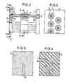
- Fig. 2 shows a sectional view of the write head structure according to Fig. 1.
- the ink channels 2 extend with their free ends 4 parallel to the front. They are encompassed over part of their length by the piezotubes 3 attached to them.
- the front free ends 4 of the ink channels 2 are inserted into openings 6 of the first layer plate 7 of the channel plate 5 and thus fixed.
- the middle layer plate 8 has recesses 14, via which the ink flow 2 is deflected and guided between the ink channels 2 and the outlet openings 15 in the third layer plate 9 takes place.
- the function of the third layer plate 9 can also be referred to as a nozzle plate. In the example according to FIG. 2, the contacting elements have no longer been shown.
- a contacting described with reference to FIG. 1 can be provided and that when a single piezo tube is actuated with a correspondingly polarized pulse in a manner known per se, this by changing its inside diameter a pressure pulse or a Pressure wave generated in the interior of the corresponding ink channel, which spreads to both sides and that a single droplet is ejected via the outlet opening 15 assigned to this ink channel.
- the ink channels 2 formed on the carrier part 1 are, in the example, as shown in FIG. 3 (section A-B), arranged in two rows offset from one another. They can be arranged at such a mutual distance that the piezo tubes can be fitted manually or automatically without problems.
- FIG. 4 and 5 show details of the channel plate 5, in each of which a section through the second layer plate 7 (section CD) and through the third layer plate 8 (section EF) is shown.
- the transition channels 14 In the middle or second layer plate 8 shown in FIG. 4 run the transition channels 14, which guide the ink flow between the ink channels 2 ending at the first layer plate 7 and the outlet openings 15 arranged in the third layer plate 9.
- the transition channels 14 can be formed as recesses in the second layer plate 8.
- the third layer plate 9 shown in FIG. 5 has the outlet openings 15 which are arranged in the division grid provided for the writing operation and which form a row in the example.
- the channel plate 5 can be made of ceramic, metal or plastic, the so-called ultrasonic welding process being used in particular for connecting plates made of plastic.
- the ink supply to the write head of the exemplary embodiment takes place via the openings 13 in the carrier part 1 of the channel block.
- These openings 13 are connected in a manner not shown here to an ink supply common for all ink channels 2 or for a certain number of ink channels, and this in turn is connected to an ink reservoir, from which, during operation of the write head under the action of the piezo tubes, the required through which Droplet ejection is used up.
- the channel plate on the rear surface of the carrier part, ie on the flat surface of the channel block.
- FIG. 6 An example of this is shown in FIG. 6.
- the channel block again consists of the carrier part 1 and the parallel ink channels 2 formed thereon. After inserting a contacting device (not shown here), the piezotubes 3 are plugged onto the ink channels 2. attached and contacted there.
- the channel plate 5 the structure of which can correspond to the previously described mounting mat, is fastened here in a spatula-free and ink-tight manner to the rear wall of the support part 1 of the channel block is, inserted via this cover plate 17, the ink supply system is connected, which in this case is common to all ink channels 2.
- it is advantageous to provide an additional support plate 18 on the front surface of the write head which in the region of the outlet openings 15 a corresponding recess 1. 9
- the entire arrangement can be completely or partially cast.
- a two-layer or a single-layer plate can also be used as the channel plate, as will be explained in the following with the aid of a few exemplary embodiments, various options being available for forming the transition channels.
- the transition channels 23 can be formed exclusively in the layer plate 21 of the channel plate 20 lying against the carrier part 1, or, as the embodiment according to FIG. 8 shows, a channel plate 24 be provided in which a part 25 of the transition channels is formed in the carrier part 1 and a second part 26 in the first layer plate 27.
- the outlet openings 15 are formed in the second layer plate 22 (FIG. 7) or 28 (FIG. 8) in accordance with the division provided for the writing operation.
- transition channels 30 and the outlet openings 15 can be arranged in the channel plate 29, as the exemplary embodiment according to FIG. 9 shows.
- the channel block and the channel plate in such a way that the outlet openings directly adjoin the ink channels.
- FIGS. 12 and 13 An example of this is shown in FIGS. 12 and 13.
- the ink channels 2 and the carrier part 1 form the unitary channel block, which can be created as a prefabricated unit.
- the ink channels 2 are arranged here along an oblique line with a pitch ta determined by the spacing of the piezo tubes 3. With their free ends 4, the ink channels 2 are inserted into the through openings 16 of the plate-shaped holding part 17.
- the connection to the ink supply system is also located on this side.
- the channel plate 31 fastened to the rear surface of the carrier part 1 represents the end of the write head facing the writing point.
- the channel plate 31 has the outlet openings 15 which have been worked out according to the position of the ink channels 2, that is to say also arranged along an oblique line, so that there is a vertical line Direction results in a pitch ts of the outlet openings 15, which is smaller than the pitch ta of the ink channels. In this embodiment, a transition channel is no longer required.
- characters are displayed in the writing mode in such a way that the writing head is moved in the direction of the arrow (FIG. 13), the height of the writing areas being determined by the inclination of the outlet openings 15 arranged along an oblique line.
Landscapes
- Particle Formation And Scattering Control In Inkjet Printers (AREA)
Applications Claiming Priority (2)
| Application Number | Priority Date | Filing Date | Title |
|---|---|---|---|
| DE3443579 | 1984-11-29 | ||
| DE3443579 | 1984-11-29 |
Publications (2)
| Publication Number | Publication Date |
|---|---|
| EP0183224A1 true EP0183224A1 (fr) | 1986-06-04 |
| EP0183224B1 EP0183224B1 (fr) | 1989-10-04 |
Family
ID=6251501
Family Applications (1)
| Application Number | Title | Priority Date | Filing Date |
|---|---|---|---|
| EP85114981A Expired EP0183224B1 (fr) | 1984-11-29 | 1985-11-26 | Tête d'écriture pour imprimante à jet d'encre |
Country Status (4)
| Country | Link |
|---|---|
| US (1) | US4665409A (fr) |
| EP (1) | EP0183224B1 (fr) |
| JP (1) | JPS61134264A (fr) |
| DE (1) | DE3573391D1 (fr) |
Cited By (2)
| Publication number | Priority date | Publication date | Assignee | Title |
|---|---|---|---|---|
| EP0260884A3 (en) * | 1986-09-17 | 1989-05-17 | International Business Machines Corporation | Print head for drop-on-demand ink jet printing apparatus |
| EP0691205A3 (fr) * | 1994-07-05 | 1996-03-20 | Francotyp Postalia Gmbh | Tête d'impression par jet d'encre modulaire |
Families Citing this family (15)
| Publication number | Priority date | Publication date | Assignee | Title |
|---|---|---|---|---|
| USRE35737E (en) * | 1986-07-09 | 1998-02-24 | Vidoejet Systems International, Inc. | Accoustically soft ink jet nozzle assembly |
| US4812859A (en) * | 1987-09-17 | 1989-03-14 | Hewlett-Packard Company | Multi-chamber ink jet recording head for color use |
| JPH02274559A (ja) * | 1989-04-18 | 1990-11-08 | Komori Corp | 画像印刷装置のヘッド |
| US5087930A (en) * | 1989-11-01 | 1992-02-11 | Tektronix, Inc. | Drop-on-demand ink jet print head |
| IL97034A (en) * | 1991-01-24 | 1994-07-31 | Carmon Amiram | Ink jet print heads utilizing fused silicon microcapillary ink channels |
| US5473354A (en) * | 1994-05-26 | 1995-12-05 | Hewlett-Packard Company | Ink-delivery apparatus |
| DE10032281A1 (de) | 2000-07-03 | 2002-01-17 | Heidelberger Druckmasch Ag | Verfahren zur Beeinflussung einer Emulsion in einer Druckmaschine |
| US6955417B2 (en) * | 2002-03-28 | 2005-10-18 | Fuji Photo Film Co., Ltd. | Inkjet recording head and inkjet printer |
| US7052117B2 (en) | 2002-07-03 | 2006-05-30 | Dimatix, Inc. | Printhead having a thin pre-fired piezoelectric layer |
| US8491076B2 (en) | 2004-03-15 | 2013-07-23 | Fujifilm Dimatix, Inc. | Fluid droplet ejection devices and methods |
| US7281778B2 (en) | 2004-03-15 | 2007-10-16 | Fujifilm Dimatix, Inc. | High frequency droplet ejection device and method |
| EP1836056B1 (fr) | 2004-12-30 | 2018-11-07 | Fujifilm Dimatix, Inc. | Impression a jet d'encre |
| US7988247B2 (en) | 2007-01-11 | 2011-08-02 | Fujifilm Dimatix, Inc. | Ejection of drops having variable drop size from an ink jet printer |
| US10004282B2 (en) | 2014-12-30 | 2018-06-26 | Jamal Taha | Surgical glove tape |
| US9464213B2 (en) | 2014-12-30 | 2016-10-11 | Jamal Taha | Surgical glove tape |
Citations (1)
| Publication number | Priority date | Publication date | Assignee | Title |
|---|---|---|---|---|
| EP0063637A2 (fr) * | 1981-04-29 | 1982-11-03 | Siemens Aktiengesellschaft | Tête d'enregistrement pour imprimante à jet d'encre avec conduites d'encre cylindriques |
Family Cites Families (7)
| Publication number | Priority date | Publication date | Assignee | Title |
|---|---|---|---|---|
| US4158847A (en) * | 1975-09-09 | 1979-06-19 | Siemens Aktiengesellschaft | Piezoelectric operated printer head for ink-operated mosaic printer units |
| JPS594309B2 (ja) * | 1979-01-31 | 1984-01-28 | 富士通株式会社 | インクジエット記録装置 |
| JPS55117665A (en) * | 1979-03-01 | 1980-09-10 | Ricoh Co Ltd | Ink jet integrated head |
| JPS55130783A (en) * | 1979-03-30 | 1980-10-09 | Canon Inc | Recording head |
| IT1144625B (it) * | 1981-08-04 | 1986-10-29 | Olivetti & Co Spa | Stampante a punti a getto d inchiostro |
| US4418356A (en) * | 1981-09-23 | 1983-11-29 | Ncr Corporation | Ink jet print head |
| DE3234408C2 (de) * | 1982-09-16 | 1986-01-09 | Siemens AG, 1000 Berlin und 8000 München | Schreibkopf mit piezoelektrischen Antriebselementen für Tintenschreibeinrichtungen |
-
1985
- 1985-11-15 US US06/798,306 patent/US4665409A/en not_active Expired - Lifetime
- 1985-11-26 EP EP85114981A patent/EP0183224B1/fr not_active Expired
- 1985-11-26 DE DE8585114981T patent/DE3573391D1/de not_active Expired
- 1985-11-28 JP JP60266290A patent/JPS61134264A/ja active Pending
Patent Citations (1)
| Publication number | Priority date | Publication date | Assignee | Title |
|---|---|---|---|---|
| EP0063637A2 (fr) * | 1981-04-29 | 1982-11-03 | Siemens Aktiengesellschaft | Tête d'enregistrement pour imprimante à jet d'encre avec conduites d'encre cylindriques |
Non-Patent Citations (3)
| Title |
|---|
| PATENTS ABSTRACTS OF JAPAN, Band 4, Nr. 150 (M-37)[632], 22. Oktober 1980; & JP - A - 55 101 466 (FUJITSU K.K.) 02.08.1980 * |
| PATENTS ABSTRACTS OF JAPAN, Band 4, Nr. 167 (M-42)[649], 19. November 1980; & JP - A - 55 117 666 (RICOH K.K.) 10.09.1980 * |
| PATENTS ABSTRACTS OF JAPAN, Band 4, Nr. 183 (M-47)[665], 17. Dezember 1980; & JP - A - 55 130 783 (CANON K.K.) 09.10.1980 * |
Cited By (2)
| Publication number | Priority date | Publication date | Assignee | Title |
|---|---|---|---|---|
| EP0260884A3 (en) * | 1986-09-17 | 1989-05-17 | International Business Machines Corporation | Print head for drop-on-demand ink jet printing apparatus |
| EP0691205A3 (fr) * | 1994-07-05 | 1996-03-20 | Francotyp Postalia Gmbh | Tête d'impression par jet d'encre modulaire |
Also Published As
| Publication number | Publication date |
|---|---|
| EP0183224B1 (fr) | 1989-10-04 |
| JPS61134264A (ja) | 1986-06-21 |
| DE3573391D1 (en) | 1989-11-09 |
| US4665409A (en) | 1987-05-12 |
Similar Documents
| Publication | Publication Date | Title |
|---|---|---|
| EP0183224A1 (fr) | Tête d'écriture pour imprimante à jet d'encre | |
| DE2543451C2 (de) | Piezoelektrisch betriebener Schreibkopf für Tintenmosaikschreibeinrichtungen | |
| DE69129159T2 (de) | Tintenstrahlkopf | |
| DE69403520T2 (de) | Herstellungsverfahren eines seitenbreitigen piezo-elektrischen Farbstrahldruckkopfes | |
| DE3248087A1 (de) | Fluessigkeitsstrahlkopf | |
| DE69514675T2 (de) | Tintenstrahlkopf und düsenplatte dafür | |
| EP0121894B1 (fr) | Tête d'écriture commandée par piézo-électricité pour dispositifs d'écriture à mosaique d'encre | |
| EP0135197A1 (fr) | Système de génération de gouttelettes pour dispositifs d'écriture à encre | |
| DE3445720A1 (de) | Anordnung zum ausstoss von einzeltroepfchen aus austrittsoeffnungen eines tintenschreibkopfes | |
| DE69402738T2 (de) | Verbindungsanordnung hoher Dichte für Tintenstrahldruckkopf | |
| EP0150348B1 (fr) | Tête d'impression à jet d'encre | |
| DE69407821T2 (de) | Herstellung eines farbstrahldruckkopfes mit zweikanalig ausgerichteter innenanordnung | |
| DE3018334C2 (fr) | ||
| DE3006726C2 (de) | Tintenschreibeinrichtung | |
| DE3820082A1 (de) | Tintenstrahl-schreibkopf | |
| EP0063637B1 (fr) | Tête d'enregistrement pour imprimante à jet d'encre avec conduites d'encre cylindriques | |
| EP0057956B1 (fr) | Tête à écrire pour une imprimante à jet d'encre | |
| DE69810799T2 (de) | Tröpfchenaufzeichnungsgerät und herstellungsverfahren | |
| DE69913079T2 (de) | Piezoelektrischer Vibratoreinheit, dessen Herstellungsverfahren und einen, diese Vibratoreinheit enthaltenden Tintenstrahlaufzeichnungskopf | |
| DE3433536C2 (de) | Tintenstrahldruckkopf | |
| EP0040784A2 (fr) | Agencement pour une tête d'impression dans un dispositif à écrire à jets d'encre en forme de matrice de points | |
| EP0131704B1 (fr) | Dispositif d'enregistrement à gouttelettes de liquide | |
| EP0326568B1 (fr) | Tete d'ecriture a l'encre a couches multiples | |
| DE69818121T2 (de) | Tintenstrahldruckkopf | |
| DE3917434C2 (fr) |
Legal Events
| Date | Code | Title | Description |
|---|---|---|---|
| PUAI | Public reference made under article 153(3) epc to a published international application that has entered the european phase |
Free format text: ORIGINAL CODE: 0009012 |
|
| 17P | Request for examination filed |
Effective date: 19860226 |
|
| AK | Designated contracting states |
Kind code of ref document: A1 Designated state(s): CH DE FR GB IT LI NL SE |
|
| 17Q | First examination report despatched |
Effective date: 19870729 |
|
| GRAA | (expected) grant |
Free format text: ORIGINAL CODE: 0009210 |
|
| AK | Designated contracting states |
Kind code of ref document: B1 Designated state(s): CH DE FR GB IT LI NL SE |
|
| PG25 | Lapsed in a contracting state [announced via postgrant information from national office to epo] |
Ref country code: SE Effective date: 19891004 Ref country code: NL Effective date: 19891004 |
|
| REF | Corresponds to: |
Ref document number: 3573391 Country of ref document: DE Date of ref document: 19891109 |
|
| ET | Fr: translation filed | ||
| PGFP | Annual fee paid to national office [announced via postgrant information from national office to epo] |
Ref country code: FR Payment date: 19891124 Year of fee payment: 5 |
|
| ITTA | It: last paid annual fee | ||
| PGFP | Annual fee paid to national office [announced via postgrant information from national office to epo] |
Ref country code: SE Payment date: 19891130 Year of fee payment: 5 Ref country code: NL Payment date: 19891130 Year of fee payment: 5 |
|
| ITF | It: translation for a ep patent filed | ||
| GBT | Gb: translation of ep patent filed (gb section 77(6)(a)/1977) | ||
| GBT | Gb: translation of ep patent filed (gb section 77(6)(a)/1977) | ||
| PGFP | Annual fee paid to national office [announced via postgrant information from national office to epo] |
Ref country code: CH Payment date: 19900222 Year of fee payment: 5 |
|
| NLV1 | Nl: lapsed or annulled due to failure to fulfill the requirements of art. 29p and 29m of the patents act | ||
| PLBE | No opposition filed within time limit |
Free format text: ORIGINAL CODE: 0009261 |
|
| STAA | Information on the status of an ep patent application or granted ep patent |
Free format text: STATUS: NO OPPOSITION FILED WITHIN TIME LIMIT |
|
| 26N | No opposition filed | ||
| PGFP | Annual fee paid to national office [announced via postgrant information from national office to epo] |
Ref country code: GB Payment date: 19901018 Year of fee payment: 6 |
|
| PG25 | Lapsed in a contracting state [announced via postgrant information from national office to epo] |
Ref country code: LI Effective date: 19901130 Ref country code: CH Effective date: 19901130 |
|
| PGFP | Annual fee paid to national office [announced via postgrant information from national office to epo] |
Ref country code: DE Payment date: 19910125 Year of fee payment: 6 |
|
| PG25 | Lapsed in a contracting state [announced via postgrant information from national office to epo] |
Ref country code: FR Effective date: 19910731 |
|
| REG | Reference to a national code |
Ref country code: CH Ref legal event code: PL |
|
| REG | Reference to a national code |
Ref country code: FR Ref legal event code: ST |
|
| PG25 | Lapsed in a contracting state [announced via postgrant information from national office to epo] |
Ref country code: GB Effective date: 19911126 |
|
| GBPC | Gb: european patent ceased through non-payment of renewal fee | ||
| PG25 | Lapsed in a contracting state [announced via postgrant information from national office to epo] |
Ref country code: DE Effective date: 19920801 |