EP0183270A2 - Verfahren zur Bestimmung des Oberflächenglanzes eines Körpers - Google Patents
Verfahren zur Bestimmung des Oberflächenglanzes eines Körpers Download PDFInfo
- Publication number
- EP0183270A2 EP0183270A2 EP85115140A EP85115140A EP0183270A2 EP 0183270 A2 EP0183270 A2 EP 0183270A2 EP 85115140 A EP85115140 A EP 85115140A EP 85115140 A EP85115140 A EP 85115140A EP 0183270 A2 EP0183270 A2 EP 0183270A2
- Authority
- EP
- European Patent Office
- Prior art keywords
- glossinesses
- curve
- measured
- light
- visible
- Prior art date
- Legal status (The legal status is an assumption and is not a legal conclusion. Google has not performed a legal analysis and makes no representation as to the accuracy of the status listed.)
- Granted
Links
Images





Classifications
-
- G—PHYSICS
- G01—MEASURING; TESTING
- G01B—MEASURING LENGTH, THICKNESS OR SIMILAR LINEAR DIMENSIONS; MEASURING ANGLES; MEASURING AREAS; MEASURING IRREGULARITIES OF SURFACES OR CONTOURS
- G01B11/00—Measuring arrangements characterised by the use of optical techniques
- G01B11/30—Measuring arrangements characterised by the use of optical techniques for measuring roughness or irregularity of surfaces
- G01B11/303—Measuring arrangements characterised by the use of optical techniques for measuring roughness or irregularity of surfaces using photoelectric detection means
-
- G—PHYSICS
- G01—MEASURING; TESTING
- G01N—INVESTIGATING OR ANALYSING MATERIALS BY DETERMINING THEIR CHEMICAL OR PHYSICAL PROPERTIES
- G01N21/00—Investigating or analysing materials by the use of optical means, i.e. using sub-millimetre waves, infrared, visible or ultraviolet light
- G01N21/17—Systems in which incident light is modified in accordance with the properties of the material investigated
- G01N21/55—Specular reflectivity
- G01N21/57—Measuring gloss
-
- G—PHYSICS
- G01—MEASURING; TESTING
- G01N—INVESTIGATING OR ANALYSING MATERIALS BY DETERMINING THEIR CHEMICAL OR PHYSICAL PROPERTIES
- G01N21/00—Investigating or analysing materials by the use of optical means, i.e. using sub-millimetre waves, infrared, visible or ultraviolet light
- G01N21/17—Systems in which incident light is modified in accordance with the properties of the material investigated
- G01N21/47—Scattering, i.e. diffuse reflection
- G01N2021/4704—Angular selective
- G01N2021/4711—Multiangle measurement
- G01N2021/4716—Using a ring of sensors, or a combination of diaphragm and sensors; Annular sensor
-
- G—PHYSICS
- G01—MEASURING; TESTING
- G01N—INVESTIGATING OR ANALYSING MATERIALS BY DETERMINING THEIR CHEMICAL OR PHYSICAL PROPERTIES
- G01N21/00—Investigating or analysing materials by the use of optical means, i.e. using sub-millimetre waves, infrared, visible or ultraviolet light
- G01N21/17—Systems in which incident light is modified in accordance with the properties of the material investigated
- G01N21/55—Specular reflectivity
- G01N2021/555—Measuring total reflection power, i.e. scattering and specular
-
- G—PHYSICS
- G01—MEASURING; TESTING
- G01N—INVESTIGATING OR ANALYSING MATERIALS BY DETERMINING THEIR CHEMICAL OR PHYSICAL PROPERTIES
- G01N21/00—Investigating or analysing materials by the use of optical means, i.e. using sub-millimetre waves, infrared, visible or ultraviolet light
- G01N21/17—Systems in which incident light is modified in accordance with the properties of the material investigated
- G01N21/55—Specular reflectivity
- G01N2021/556—Measuring separately scattering and specular
-
- G—PHYSICS
- G01—MEASURING; TESTING
- G01N—INVESTIGATING OR ANALYSING MATERIALS BY DETERMINING THEIR CHEMICAL OR PHYSICAL PROPERTIES
- G01N21/00—Investigating or analysing materials by the use of optical means, i.e. using sub-millimetre waves, infrared, visible or ultraviolet light
- G01N21/17—Systems in which incident light is modified in accordance with the properties of the material investigated
- G01N21/25—Colour; Spectral properties, i.e. comparison of effect of material on the light at two or more different wavelengths or wavelength bands
- G01N21/31—Investigating relative effect of material at wavelengths characteristic of specific elements or molecules, e.g. atomic absorption spectrometry
- G01N21/314—Investigating relative effect of material at wavelengths characteristic of specific elements or molecules, e.g. atomic absorption spectrometry with comparison of measurements at specific and non-specific wavelengths
Definitions
- This invention relates to a method of and an apparatus for determining glossinesses of a surface of a body, and more particularly to improvements in a method of and an apparatus for determining glossinesses of a surface of a body, suitable for use in measuring the surface quality of a steel sheet to control the same, wherein the glossinesses based on the visible feeling are classified and graded in accordacne with the light reflection intensity distribution of the surface of the body.
- the method of measuring by the specular surface glossiness is widely used in industries, but, present such a disadvantage that, as for the specular surface object having a low surface roughness, the results of measurement do not coincide with the actual facts. Furthermore, the method of measuring by the contrasting glossinesses has the characteristics of giving the glossiness-close to the visible feeling to objects different in color from one another, but has a tendency of being lowered in the accuracy of determining the glossinesses with the objects close to the specular surface. Further, the method of measuring by the sharp glossiness is disadvantageous in that no quantitative indication can be obtained.
- the present invention has been developed to obviate the disadvantages of the prior art and has as its object the provision of a method of and an apparatus for determining glossinesses of a surface of a body, wherein, with objects being identical in color with one another (may be different in luminosity from one another), the result of measurement coincide with the visible glossinesses and the golssinesses can be determined quantitatively over a wide range of roughness degrees from the specular surface to the rough surface.
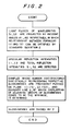
- the present invention contemplates that, in a method of determining glossinesses of a surface of a body, wherein the glossinesses based on the visible feeling are classified and graded in accordance with the light reflection intensity distribution of the surface of the body, as the gist thereof is shown in Fig.
- a specific form of the present invention is of such an arragement that centroid points of the respective visible glossinesses are selected as the representative points, so that the adequate representative points can be easily obtained.
- Another specific form of the present invention is of such an arrangement that the curve 1 is determined by a construction in a drawing so that the adequate curve 1 can be easily obtained.
- a further specific form of the present invention is of suc an arrangement that the straight lines m are obtained by plotting a multiplicity of sample points, whereby the number of points turned to be mistakenly determined can be limited to the minimum for the adjoining groups, so that adequate straight line m can be easily obtained.
- the present invention contemplates that, further, the glossiness of an arbitrary work to be measured is evaluate by a distance from a reference point R on the curve 1 alon the curve 1 to a foot Q of a perpendicularly drawn line from a point P on the two dimensional plane of the work to be measured to the curve 1.
- a still further specific form of the present invention is of such an arrangement that the glossiness of an arbitrary point on the curve 1 is determined to be a proportionally interpolated value along the curve 1 in each of section, and the glossiness of an arbitrary sample is made to be the glossiness of a point at which is positioned a foot Q of a perpendicularly drawn line from a point P associated with the comple on the two dimcncional plane to the curve 1, no that the glossiness of the arbitrary sample can be quantitatively obtained.
- the present invention contemplates that, in a method of determining the glossinesses of a surface of a body, wherein the golssinesses based on the visible feeling arc classified and graded in accordance with the light reflection intensity distribution of the surface of the body, as the gist thereof is shown in Fig.
- a yet further specific form of the present invention is of such an arrangement that the boundary line Z is determined such that, when two dimensional distributions of adjoining groups are projected on an axis Zv normal to the boundary line Z, the overlapping formed there comes to be the minimum, so that the adequate boundary line Z can be easil obtained.
- the present invention contemplates that, in an apparatus for determining glossinesses of a surface of a body, wherein the glossinesses based on the visible feeling are classified and graded in accordacne with the light reflection intensity distribution of the surface of the body, as the gist of arrangeement :hereof is shown in Fig.
- the apparatus comprisest two light sources 14A and 14B, which project light fluxes 12A and 12B having wavelenghts ⁇ 1 and ⁇ 2, by which a standard deviation ⁇ of a height distribution of the profile of a surface to be measured satisfies the relationship between the above-mentioned formulae (1) and (2), at incident angles ⁇ 1 and ⁇ 2, respectively; two light receivers 16A and 16B for detecting respective specular reflection intensities Il and I2 and respective ! total reflection intensities S1 and S2, and a processing section 18 for processing the specular reflection intensities Il, I2 and the total reflection intensities Sl, S2 to thereby divide glossinesses of a work 10 to be measured.
- a specific form of the present invention is of such an arrangement that the light receiver comprises photodiodes arranged in a two dimensional array form, so that the specular and total refrection intensities can be detected easily with no movable parts.
- Another specific form of the present invention is of such an arrangement that the light receiver has an aperture provided in front thereof and the opening area of the aperture is made variable, so that the specular and total reflection intensities can be detected easily.
- the present invention is based on the fact that the visible glossinesses of a surface of a body such as a steel sheet rely upon parameters of two surface roughness degrees including the averaged roughness and the averaged interval between crcets, and evaluation cannot be performed only by the averaged roughness.
- the surface roughness is the main facto in determining the glossinesses of objects having colors substantially identical with each other, and it is basically considered that, when information of the surface roughness is accurately grasped, the glossinesses can be evaluated.
- the information of the surface roughness can be expressed by the standard deviation ⁇ of the height distribution of the profile of the surface to be measured and an auto-correlation distance T (a distance, where an auto-correlation function becomes 1/e), the value and the light reflection intensity distribution have a predetermined relationship as shown in "The Scattering of Electromagnetic Waves from Rough Surfaces" under a joint authorship of P, Beckmann and A. Sprizzichino, published by Pergamon Press in 1963.
- the specular reflectior intensities I1 and I2 have the relationships shown in the following equations with the parameters of the roughness degree ⁇ and T. where the incident light intensity is a unit intensity and the total reflection factor is 1.
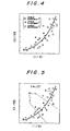
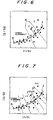
- the inventor of the present invention has thought of the following method as a method, wherein this classification is performed more ordinarily. More specifically, the representative points of the respective visible glossinesses are plotted on the two dimensional plane (I1/S1, 1 2/82), the curve 1 obtained by smoothly connecting these points is determined by a construction on a drawing, for example. Subsequently, the glossiness of an arbitrary sample is evaluated by a distance (or a value equivalent ; thereto) from a reference point R on the curve 1 along the curve 1 to a foot Q of a perpendicularly drawn line from a point P of the sample on the two dimensional plane. Fig. shows the simpliest example wherein the sample points are classified in accordance with the visible glossinesses 1, and 3. F ig. 7 shows an example wherein these visible glossinesses are further finely evaluated.
- a multiplicity of samples having the I qualities of types identical with one another, but being different in visible glossiness from one another are plotted on the two dimensional plane (I1/B1, I2/S2), as shown in Fig. 8 for example, there are also many oases where these samples are distributed on the two dimensional plane, being divided into a plurality of groups in accordance with the glossinesses thereof.
- designated at o is a sample having the visible glossiness 1, ⁇ a sample having the visible glossiness 2 and ⁇ a sample having the visible glossiness 3, respectively,
- the boundary line Z is determined such that the overlapping between the respective adjoining groups of the glossinesses comes to be statiscally the minimum, and the samples are divided.
- the boundary line Z for making the statistic overlapping between the two adjoining groups be the minimum is derived by use of a discriminant function. As shown in Fig. 9 for example, this boundary line Z can be determined such that, when the two dimensional distributions of the adjoining groups are projected onto an axis Zv normal to the boundary line Z, the overlapping there comes to be minimum.
- a boundary line Z12 between the glossinesses 1 and 2 and a boundary line Z23 between the glossinesses 2 and 3 of the groups of glossinesses as shown in Fig. 8 are determined, and the divided state is shown in Fig. 10.
- the boundary line Z23 between the gloesinesse 2 and 3 as shown in an example of Fig. 10 is determined as shown below. More specifically, when data shown in Table 1 are obtained on the respective glossinesses, the following statistics are calculated by the following equations.
- equations (5) and (6) have sought mean values
- equation (9) has sought the sum of squares in group and the sum of products
- equation (10) has sought the variance in group and the covariance.
- the boundary line Z as being the discriminant function can be determined from the above-mentioned statistics through the following equations.
- the glossinesses of the surface of the work 10 to be measured can be determined in such a manner that the light fluxes 12A and 12B are projected to the surface of the work 10 to be measured from the two light sources 14A and 14B having the wavelengths ⁇ 1 and X2 and the incident angles ⁇ 1 and ⁇ 2 which satisfy the conditions of the above-mentioned formulae (1) and (2), the specular reflection intensities I1, 12 and the total reflection intensities 81, S2 are detected by the light receivers 16A and 16B, and the specular reflection intensities 11, 12 and the total reflection intensities Sl, S2 are adequately processed by the processing section 18 in accordance with the first or the second method.
- the light receiver 16A (16B) for detecting the specular reflection intensity I1 (I2) and the total reflection intensity Sl (B2) as shown in Fig. 11 for example, use of such a light receiver 16A (16B) may be thought of, that photodiodes 20A, 20B, 20C Vietnamese are arranged in a two dimensional array form, out of these photodiodes, the quantity of detected light of the specific photodiode which is on the specular reflecting direction becomes the specular reflection intensity I1 (I2) and the total sum of the entire light receiving values becomes the total reflection intensity S1 (S2).
- such a light receiver 16a (16B) may be thought of, that an aperture 22 is provided in front of the light receiver 16A (16B) and the opening area of the aperture 22 is made variable, so that the specular reflection intensities 11 (I2) and the total reflection intensities S1 (S2) can be detected.
- the glossinesses coinciding with the visible glossinesses and widely ranging in roughness degree from the specular surface to the rough surface can be quantitatively determined. In consequence, it becomes possible to accurately measure and control the surface qualities at on-line, so that outstanding practical advantages such as the prevention of the occurrence of defectives can be offered.
- This first embodiment is provided to test the performance of the automatic determination for the purpose of replacing the determination of the glossinesses under the conventional visual inspection (four grades of the glossinesses 1 to 4) by the automatic determination through the measurement of the light reflection intensities I1 and 12.
- the total reflection factors are substantially constant, and the two dimensional plane (I1/S1, I2/S2) used in the evaluation of the glossinesses is equivalent to (11, 12).
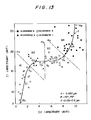
- Fig. 13 shows the result of determination by this first embodiment.
- the respective samples are classified into four grades of the glossinesses 1 to 4 through the visual inspection made by a plurality of skilled inspectors by comparing the samples with the reference samples.
- O, ⁇ , ⁇ and ⁇ indicate the samples having the glossinesses 1, 2, 3 and 4, respectively.
- the glossinesses at the respective representative points Cl, C 2, C3 and C4 are made to be 1.0, 2.0, 3.0 and 4.0
- the glossinesses of one Rs of reference points, a point of intersection Ta between the curve 1 and the boundary line ma, a point of intersection Tb between the curve 1 and the boundary line mb, a point of intersection To between the curve 1 and the boundary line mo the other Rs of reference points are made to be 0.5, 1.5, 2.5, 3.5 and 4.5, respectively
- the glossinesses of arbitrary points on the curve 1 are to be proportionally interpolated values along the curve 1 in respective sections (0.5 to 1.0, 1.0 to 1.5 .
- the determination of glossiness of analogue type can be performed by this method.
- This second method is also provided to test the performance of the automatic determination for the purpose of replacing the determination of the glossinesses under the conventional visual inspection (four grades of the glossinesses 1 to 4) by the automatic determinetion through the measurement of the light reflection intensities I1 and 12.
- the parameter ⁇ of the surface roughness of the cold-rolled steel sheet treated here is 0.1 to 0.5 micrometer.
- the total reflection factor is substantially constant, and the two dimensional plane (I1/S1, I2/S2) used for the evaluation of the glossinesses is equivalent in value to the two dimensional plate (I1, I2).
- Fig. 14 shows the result of determination by the second embodiment.
- the respective samples were classified into four grades of the glassinesses 1 to 4 through the visual inspection made by a plurality of skilled inspectors by comparing the samples with the reference samples.
- O, ⁇ , ⁇ and ⁇ indicate the samples having the glossinesses 1, 2, 3 and 4, respectively.
- the glossinesses of a multiplicity of samples of the cold-rolled steel sheet were determined by use of the boundary lines Z34, Z23 and Z12 thus determined. As a result, the determination of glossinesses of about 90% of the samples was accurately performed, whereby the method was ascertained to have a satisfactory determining capacity.
- the present invention has been applied to the evaluation and determination of glossinesses of the stainless steel sheet and the cold-rolled steel sheet, however, the scope of application of the present invention need not necessarily be limited to this, and it is apparent that the present invention is applicable to the determination of glossinesses on the surface of an ordinary body.
Landscapes
- Physics & Mathematics (AREA)
- General Physics & Mathematics (AREA)
- Health & Medical Sciences (AREA)
- Life Sciences & Earth Sciences (AREA)
- Chemical & Material Sciences (AREA)
- Analytical Chemistry (AREA)
- Biochemistry (AREA)
- General Health & Medical Sciences (AREA)
- Immunology (AREA)
- Pathology (AREA)
- Investigating Or Analysing Materials By Optical Means (AREA)
- Spectrometry And Color Measurement (AREA)
Applications Claiming Priority (6)
| Application Number | Priority Date | Filing Date | Title |
|---|---|---|---|
| JP59253529A JPS61130857A (ja) | 1984-11-30 | 1984-11-30 | 物体表面の光沢度判定方法 |
| JP59253530A JPS61130858A (ja) | 1984-11-30 | 1984-11-30 | 物体表面の光沢度判定方法 |
| JP253529/84 | 1984-11-30 | ||
| JP253530/84 | 1984-11-30 | ||
| JP26663885A JPS62126331A (ja) | 1985-11-27 | 1985-11-27 | 物体表面の光沢度判定装置 |
| JP266638/85 | 1985-11-27 |
Publications (3)
| Publication Number | Publication Date |
|---|---|
| EP0183270A2 true EP0183270A2 (de) | 1986-06-04 |
| EP0183270A3 EP0183270A3 (en) | 1986-09-17 |
| EP0183270B1 EP0183270B1 (de) | 1990-08-08 |
Family
ID=27334240
Family Applications (1)
| Application Number | Title | Priority Date | Filing Date |
|---|---|---|---|
| EP85115140A Expired EP0183270B1 (de) | 1984-11-30 | 1985-11-29 | Verfahren zur Bestimmung des Oberflächenglanzes eines Körpers |
Country Status (4)
| Country | Link |
|---|---|
| US (1) | US4750140A (de) |
| EP (1) | EP0183270B1 (de) |
| CA (1) | CA1240052A (de) |
| DE (1) | DE3579119D1 (de) |
Cited By (5)
| Publication number | Priority date | Publication date | Assignee | Title |
|---|---|---|---|---|
| EP0519409A3 (en) * | 1991-06-17 | 1993-06-30 | Keyence Corporation | Luster detector |
| EP0786643A3 (de) * | 1996-02-05 | 1998-03-04 | FIRMA F+O ELECTRONIC SYSTEMS GmbH | Vorrichtung zur Inspektion der Oberfläche von Holz zwecks Feststellung von Oberflächenmerkmalen und Vervahren hierzu |
| US7315379B2 (en) | 2005-03-22 | 2008-01-01 | Canon Kabushiki Kaisha | Evaluating method and apparatus thereof |
| EP2881762A3 (de) * | 2013-12-05 | 2015-07-08 | Sick Ag | Optoelektronischer Sensor und Verfahren zur Erfassung glänzender Objekte |
| CN115930847A (zh) * | 2022-09-30 | 2023-04-07 | 中国科学院武汉岩土力学研究所 | 一种三维结构面粗糙度评价指标的定量确定方法 |
Families Citing this family (50)
| Publication number | Priority date | Publication date | Assignee | Title |
|---|---|---|---|---|
| US5133019A (en) * | 1987-12-03 | 1992-07-21 | Identigrade | Systems and methods for illuminating and evaluating surfaces |
| US4864150A (en) * | 1988-02-09 | 1989-09-05 | Russell Corporation | Method for inspecting, detecting and distinguishing sides of fabrics |
| JP2966869B2 (ja) * | 1988-10-14 | 1999-10-25 | ビク ガードナー ゲーエムベーハー | 光沢測定装置及び方法 |
| JP2918045B2 (ja) * | 1988-10-28 | 1999-07-12 | 株式会社リコー | 画像濃度制御装置 |
| US4992963A (en) * | 1988-12-02 | 1991-02-12 | Simon Fraser University | Method and apparatus for determining ambient light and surface reflectance |
| US4957368A (en) * | 1989-03-16 | 1990-09-18 | Photoacoustic Technology, Inc. | Apparatus and process for performing ellipsometric measurements of surfaces |
| DE4243885A1 (de) * | 1992-12-23 | 1994-06-30 | Fogra Forschungsgesellschaft D | Verfahren und Anordnung zur Messung von Farbe und Glanz |
| US5552890A (en) * | 1994-04-19 | 1996-09-03 | Tricor Systems, Inc. | Gloss measurement system |
| DE4434203C2 (de) * | 1994-09-24 | 2003-06-12 | Byk Gardner Gmbh | Vorrichtung und Verfahren zum Messen visueller Eigenschaften von Oberflächen |
| US6294327B1 (en) * | 1997-09-08 | 2001-09-25 | Affymetrix, Inc. | Apparatus and method for detecting samples labeled with material having strong light scattering properties, using reflection mode light and diffuse scattering |
| JP2000090233A (ja) * | 1998-09-08 | 2000-03-31 | Olympus Optical Co Ltd | 画像処理装置 |
| SE521948C2 (sv) * | 1998-12-17 | 2003-12-23 | Act Ab | Mätinstrument och förfarande för mätning av damm- och smutsbeläggningsgrad på en yta |
| DE19930688A1 (de) * | 1999-07-02 | 2001-01-04 | Byk Gardner Gmbh | Vorrichtung und Verfahren zur Bestimmung der Qualität von Oberflächen |
| GB9921826D0 (en) * | 1999-09-15 | 1999-11-17 | Rhopoint Instrumentation Limit | Glossmeter |
| US6914684B1 (en) * | 2001-07-05 | 2005-07-05 | Lexmark International, Inc. | Method and apparatus for detecting media type |
| JP3870044B2 (ja) * | 2001-07-25 | 2007-01-17 | 株式会社日立製作所 | パターン検査方法及びパターン検査装置 |
| US6909791B2 (en) * | 2002-04-03 | 2005-06-21 | General Phosphorix, Llc | Method of measuring a line edge roughness of micro objects in scanning microscopes |
| JP4210466B2 (ja) * | 2002-04-22 | 2009-01-21 | 日立オムロンターミナルソリューションズ株式会社 | 判別装置 |
| WO2004063733A1 (en) * | 2003-01-09 | 2004-07-29 | Matsushita Electric Industrial Co., Ltd. | Image recognition apparatus and image recognition method |
| JP4366104B2 (ja) * | 2003-04-17 | 2009-11-18 | 日立オムロンターミナルソリューションズ株式会社 | 紙葉類判別装置 |
| JP3566276B1 (ja) * | 2003-05-07 | 2004-09-15 | 株式会社日立製作所 | 血糖値測定装置 |
| JP3566277B1 (ja) * | 2003-06-23 | 2004-09-15 | 株式会社日立製作所 | 血糖値測定装置 |
| JP3566278B1 (ja) * | 2003-07-11 | 2004-09-15 | 株式会社日立製作所 | 血糖値測定装置 |
| DE10336493A1 (de) * | 2003-08-08 | 2005-03-03 | Byk-Gardner Gmbh | Vorrichtung und Verfahren zur Bestimmung von Oberflächeneigenschaften |
| JP3590047B1 (ja) * | 2003-09-24 | 2004-11-17 | 株式会社日立製作所 | 光学測定装置及びそれを用いた血糖値測定装置 |
| EP1522254A1 (de) * | 2003-10-08 | 2005-04-13 | Hitachi, Ltd. | Vorrichtung zur Messung des Blutzuckerspiegels |
| JP3590049B1 (ja) * | 2003-12-03 | 2004-11-17 | 株式会社日立製作所 | 血糖値測定装置 |
| JP3859158B2 (ja) * | 2003-12-16 | 2006-12-20 | セイコーエプソン株式会社 | マイクロレンズ用凹部付き基板、マイクロレンズ基板、透過型スクリーン、およびリア型プロジェクタ |
| JP3557424B1 (ja) * | 2004-02-17 | 2004-08-25 | 株式会社日立製作所 | 血糖値測定装置 |
| JP3557425B1 (ja) * | 2004-02-17 | 2004-08-25 | 株式会社日立製作所 | 血糖値測定装置 |
| JP3590053B1 (ja) * | 2004-02-24 | 2004-11-17 | 株式会社日立製作所 | 血糖値測定装置 |
| JP3590054B1 (ja) * | 2004-02-26 | 2004-11-17 | 株式会社日立製作所 | 血糖値測定装置 |
| CN100337589C (zh) * | 2004-02-27 | 2007-09-19 | 株式会社日立制作所 | 血糖值测定装置 |
| JP3868963B2 (ja) * | 2004-05-10 | 2007-01-17 | 株式会社日立製作所 | 血糖値測定装置 |
| US7215983B2 (en) * | 2004-06-30 | 2007-05-08 | Hitachi, Ltd. | Blood sugar level measuring apparatus |
| US7251517B2 (en) * | 2004-06-30 | 2007-07-31 | Hitachi, Ltd. | Blood sugar level measuring apparatus |
| JP3884036B2 (ja) * | 2004-08-25 | 2007-02-21 | 株式会社日立製作所 | 血糖値測定装置 |
| JP2006094992A (ja) * | 2004-09-29 | 2006-04-13 | Hitachi Ltd | 血糖値測定装置及び血糖値測定方法 |
| JP2006115948A (ja) * | 2004-10-19 | 2006-05-11 | Hitachi Ltd | 血糖値測定装置 |
| JP2006115947A (ja) * | 2004-10-19 | 2006-05-11 | Hitachi Ltd | 血糖値測定装置 |
| DE102005031957B4 (de) * | 2005-07-08 | 2007-03-22 | Koenig & Bauer Ag | Vorrichtung zur Inspektion eines Bedruckstoffes mit uneinheitlich reflektierenden Oberflächen |
| AU2007217794A1 (en) * | 2006-02-16 | 2007-08-30 | Clean Earth Technologies, Llc | Method for spectral data classification and detection in diverse lighting conditions |
| US7619740B2 (en) * | 2007-10-11 | 2009-11-17 | Honeywell International Inc. | Microgloss measurement of paper and board |
| US8582116B2 (en) * | 2009-04-14 | 2013-11-12 | Canon Kabushiki Kaisha | Recording sheet surface detection apparatus and image forming apparatus |
| DE102010032600A1 (de) * | 2010-07-28 | 2012-02-02 | Byk-Gardner Gmbh | Vorrichtung und Verfahren zur Bestimmung von Oberflächeneigenschaften mit Mehrfachmessung |
| US8637112B2 (en) * | 2010-10-15 | 2014-01-28 | Axalta Coating Systems Ip Co., Llc | Process for predicting gloss of low gloss coating by wet color measurement |
| US9008984B2 (en) * | 2010-10-15 | 2015-04-14 | Axalta Coating Systems Ip Co., Llc | Device for predicting gloss of low gloss coating by wet color measurement |
| WO2013067220A1 (en) * | 2011-11-01 | 2013-05-10 | U.S. Coatings Ip Co. Llc | Process for predicting metallic gloss of coating resulting from coating compositions by wet color measurement |
| DE102014108789B4 (de) * | 2014-06-24 | 2026-01-29 | Byk-Gardner Gmbh | Mehrstufiges Verfahren zur Untersuchung von Oberflächen sowie entsprechende Vorrichtung |
| DE102021101594B3 (de) * | 2021-01-26 | 2022-01-05 | Carl Zeiss Spectroscopy Gmbh | Messanordnung zum Messen von diffus reflektiertem Licht und von spekular reflektiertem Licht |
Family Cites Families (7)
| Publication number | Priority date | Publication date | Assignee | Title |
|---|---|---|---|---|
| DE1944088U (de) * | 1966-06-16 | 1966-08-11 | Bayer Ag | Vorrichtung zur beurteilung der glanzeigenschaften von oberflaechen. |
| US4124803A (en) * | 1976-12-22 | 1978-11-07 | Kenneth Bowers | Surface finish monitor |
| US4408880A (en) * | 1981-09-22 | 1983-10-11 | Chugai Seiyaku Kabushiki Kaisha | Laser nephelometric system |
| DD208670A1 (de) * | 1982-06-29 | 1984-04-04 | Pentacon Dresden Veb | Vorrichtung zur schnellen messung des glanzes beliebiger oberflaechen |
| FI65332C (fi) * | 1982-06-29 | 1984-04-10 | Labsystems Oy | Foerfarande foer maetning i tvao prov av skillnaden av optiskaegenskaper beroende av ljusets riktning |
| JPS6097204A (ja) * | 1983-11-01 | 1985-05-31 | Senjiyou Seiki Kk | 光反射型入力レベル相対出力方式を使用した被検査体の数量のカウント出力方法 |
| US4585343A (en) * | 1983-11-04 | 1986-04-29 | Libbey-Owens-Ford Company | Apparatus and method for inspecting glass |
-
1985
- 1985-11-29 CA CA000496546A patent/CA1240052A/en not_active Expired
- 1985-11-29 US US06/802,742 patent/US4750140A/en not_active Expired - Fee Related
- 1985-11-29 EP EP85115140A patent/EP0183270B1/de not_active Expired
- 1985-11-29 DE DE8585115140T patent/DE3579119D1/de not_active Expired - Fee Related
Cited By (6)
| Publication number | Priority date | Publication date | Assignee | Title |
|---|---|---|---|---|
| EP0519409A3 (en) * | 1991-06-17 | 1993-06-30 | Keyence Corporation | Luster detector |
| EP0786643A3 (de) * | 1996-02-05 | 1998-03-04 | FIRMA F+O ELECTRONIC SYSTEMS GmbH | Vorrichtung zur Inspektion der Oberfläche von Holz zwecks Feststellung von Oberflächenmerkmalen und Vervahren hierzu |
| US7315379B2 (en) | 2005-03-22 | 2008-01-01 | Canon Kabushiki Kaisha | Evaluating method and apparatus thereof |
| EP2881762A3 (de) * | 2013-12-05 | 2015-07-08 | Sick Ag | Optoelektronischer Sensor und Verfahren zur Erfassung glänzender Objekte |
| CN115930847A (zh) * | 2022-09-30 | 2023-04-07 | 中国科学院武汉岩土力学研究所 | 一种三维结构面粗糙度评价指标的定量确定方法 |
| CN115930847B (zh) * | 2022-09-30 | 2023-09-22 | 中国科学院武汉岩土力学研究所 | 一种三维结构面粗糙度评价指标的定量确定方法 |
Also Published As
| Publication number | Publication date |
|---|---|
| DE3579119D1 (de) | 1990-09-13 |
| EP0183270A3 (en) | 1986-09-17 |
| EP0183270B1 (de) | 1990-08-08 |
| CA1240052A (en) | 1988-08-02 |
| US4750140A (en) | 1988-06-07 |
Similar Documents
| Publication | Publication Date | Title |
|---|---|---|
| EP0183270A2 (de) | Verfahren zur Bestimmung des Oberflächenglanzes eines Körpers | |
| US5367378A (en) | Highlighted panel inspection | |
| US4966455A (en) | Real time mottle measuring device and method | |
| EP2749865B1 (de) | Vorrichtung zur Messung von Reflexionseigenschaften | |
| Funck et al. | Measuring surface roughness on wood: a comparison of laser-scatter and stylus-tracing approaches | |
| US5122672A (en) | Surface quality analyzer apparatus and method | |
| EP1211478A2 (de) | Abstandsbestimmung | |
| US4213708A (en) | Graininess sensor | |
| US4710808A (en) | Machine vision differential measurement system | |
| EP0585893B1 (de) | Verfahren und Vorrichtung zur hochgenauen Abstandsmessung von Oberflächen | |
| US5701179A (en) | Method and system for measuring dimensions of an edge of a part | |
| JPH0472551A (ja) | 金属板の表面性状測定方法及びその装置 | |
| US4717259A (en) | Luster rating method and apparatus | |
| JPH0219420B2 (de) | ||
| Griffiths et al. | Light scattering for the measurement of surface finish: a review | |
| EP0131710B1 (de) | Verfahren zur Bestimmung der Oberflächenrauigkeit unter Verwendung einer Laserquelle mit sichtbarem und infrarotem Licht | |
| EP0528915B1 (de) | Verfahren und vorrichtung zur bestimmung der bildklarheit einer oberfläche | |
| US7570369B2 (en) | Method and a device for measurement of edges | |
| JPH037897B2 (de) | ||
| Tanaka | Simulation Analysis of Optimal Camera Viewpoints for Glossy-Surface Inspection. | |
| US3583216A (en) | Surface finish analyzer | |
| JPH0224458B2 (de) | ||
| Shibata et al. | On-line glossmeter for stainless steel sheets | |
| Milana et al. | An optical method for on-line evaluation of machined surface finishing | |
| DE10027439B4 (de) | Verfahren und Vorrichtung zur Bewertung von Topographieparametern periodischer Oberflächenstrukturen |
Legal Events
| Date | Code | Title | Description |
|---|---|---|---|
| PUAI | Public reference made under article 153(3) epc to a published international application that has entered the european phase |
Free format text: ORIGINAL CODE: 0009012 |
|
| AK | Designated contracting states |
Kind code of ref document: A2 Designated state(s): DE FR GB |
|
| PUAL | Search report despatched |
Free format text: ORIGINAL CODE: 0009013 |
|
| AK | Designated contracting states |
Kind code of ref document: A3 Designated state(s): DE FR GB |
|
| 17P | Request for examination filed |
Effective date: 19870302 |
|
| 17Q | First examination report despatched |
Effective date: 19880722 |
|
| GRAA | (expected) grant |
Free format text: ORIGINAL CODE: 0009210 |
|
| AK | Designated contracting states |
Kind code of ref document: B1 Designated state(s): DE FR GB |
|
| REF | Corresponds to: |
Ref document number: 3579119 Country of ref document: DE Date of ref document: 19900913 |
|
| ET | Fr: translation filed | ||
| PLBE | No opposition filed within time limit |
Free format text: ORIGINAL CODE: 0009261 |
|
| STAA | Information on the status of an ep patent application or granted ep patent |
Free format text: STATUS: NO OPPOSITION FILED WITHIN TIME LIMIT |
|
| 26N | No opposition filed | ||
| PGFP | Annual fee paid to national office [announced via postgrant information from national office to epo] |
Ref country code: FR Payment date: 19971112 Year of fee payment: 13 |
|
| PGFP | Annual fee paid to national office [announced via postgrant information from national office to epo] |
Ref country code: GB Payment date: 19971120 Year of fee payment: 13 |
|
| PGFP | Annual fee paid to national office [announced via postgrant information from national office to epo] |
Ref country code: DE Payment date: 19971205 Year of fee payment: 13 |
|
| PG25 | Lapsed in a contracting state [announced via postgrant information from national office to epo] |
Ref country code: GB Free format text: LAPSE BECAUSE OF NON-PAYMENT OF DUE FEES Effective date: 19981129 |
|
| GBPC | Gb: european patent ceased through non-payment of renewal fee |
Effective date: 19981129 |
|
| PG25 | Lapsed in a contracting state [announced via postgrant information from national office to epo] |
Ref country code: FR Free format text: LAPSE BECAUSE OF NON-PAYMENT OF DUE FEES Effective date: 19990730 |
|
| REG | Reference to a national code |
Ref country code: FR Ref legal event code: ST |
|
| PG25 | Lapsed in a contracting state [announced via postgrant information from national office to epo] |
Ref country code: DE Free format text: LAPSE BECAUSE OF NON-PAYMENT OF DUE FEES Effective date: 19990901 |