EP0183278A2 - Procédé et dispositif pour fabrication de tuyau en matière plastique longue par moulage par injection - Google Patents
Procédé et dispositif pour fabrication de tuyau en matière plastique longue par moulage par injection Download PDFInfo
- Publication number
- EP0183278A2 EP0183278A2 EP85115205A EP85115205A EP0183278A2 EP 0183278 A2 EP0183278 A2 EP 0183278A2 EP 85115205 A EP85115205 A EP 85115205A EP 85115205 A EP85115205 A EP 85115205A EP 0183278 A2 EP0183278 A2 EP 0183278A2
- Authority
- EP
- European Patent Office
- Prior art keywords
- die
- tube
- injection molding
- core
- machine according
- Prior art date
- Legal status (The legal status is an assumption and is not a legal conclusion. Google has not performed a legal analysis and makes no representation as to the accuracy of the status listed.)
- Granted
Links
Images

Classifications
-
- B—PERFORMING OPERATIONS; TRANSPORTING
- B29—WORKING OF PLASTICS; WORKING OF SUBSTANCES IN A PLASTIC STATE IN GENERAL
- B29C—SHAPING OR JOINING OF PLASTICS; SHAPING OF MATERIAL IN A PLASTIC STATE, NOT OTHERWISE PROVIDED FOR; AFTER-TREATMENT OF THE SHAPED PRODUCTS, e.g. REPAIRING
- B29C45/00—Injection moulding, i.e. forcing the required volume of moulding material through a nozzle into a closed mould; Apparatus therefor
- B29C45/17—Component parts, details or accessories; Auxiliary operations
- B29C45/26—Moulds
- B29C45/261—Moulds having tubular mould cavities
-
- B—PERFORMING OPERATIONS; TRANSPORTING
- B29—WORKING OF PLASTICS; WORKING OF SUBSTANCES IN A PLASTIC STATE IN GENERAL
- B29C—SHAPING OR JOINING OF PLASTICS; SHAPING OF MATERIAL IN A PLASTIC STATE, NOT OTHERWISE PROVIDED FOR; AFTER-TREATMENT OF THE SHAPED PRODUCTS, e.g. REPAIRING
- B29C45/00—Injection moulding, i.e. forcing the required volume of moulding material through a nozzle into a closed mould; Apparatus therefor
- B29C45/17—Component parts, details or accessories; Auxiliary operations
- B29C45/40—Removing or ejecting moulded articles
-
- B—PERFORMING OPERATIONS; TRANSPORTING
- B29—WORKING OF PLASTICS; WORKING OF SUBSTANCES IN A PLASTIC STATE IN GENERAL
- B29C—SHAPING OR JOINING OF PLASTICS; SHAPING OF MATERIAL IN A PLASTIC STATE, NOT OTHERWISE PROVIDED FOR; AFTER-TREATMENT OF THE SHAPED PRODUCTS, e.g. REPAIRING
- B29C45/00—Injection moulding, i.e. forcing the required volume of moulding material through a nozzle into a closed mould; Apparatus therefor
- B29C45/17—Component parts, details or accessories; Auxiliary operations
- B29C45/40—Removing or ejecting moulded articles
- B29C2045/4089—Hollow articles retained in the female mould during mould opening
Definitions
- the invention relates to a plastic pipe and a method and a device for its production according to the preambles of claims 1, 5 and 16.
- plastic pipes can be easily produced by extrusion, their production by injection molding is often desirable in order to obtain a very smooth, shiny surface on their outer jacket.
- extrusion which supplies seamless and endless tubes
- the injection molding of long and seamless tubes has so far not been possible. This is particularly due to the fact that when using the conventional injection molding process or injection molding machines, difficulties arise both with regard to the removal of the finished tube from the injection molding tool and with regard to the construction of injection molding machines with an acceptable overall length or overall height.
- tools with a hollow cylindrical or similarly shaped cavity are required, which consist of a completely closed die and a core that can be inserted into it.
- these long pipes including pipes from one Length of about 50 cm and a length-diameter ratio of about 10: 1, preferably about 30: 1, which also have no taper on the outside or inside, exist in the demolding, in particular when the tubes are pulled out of the die the risk that the sensitive outer jacket of the tube rubs against the inner jacket of the die and is thereby provided with surface grooves or is otherwise damaged.
- the tube sticks to the core due to its shrinkage and can then no longer be detached from it without damage, particularly to the end faces.
- the injection molding machine would have to have an overall length or height in the area in which the injection mold is located and demolding takes place, which corresponds to at least three times the length of the tube, otherwise the finished tubes would not be freely accessible after demolding could be removed from the injection molding machine. As a result, the space requirement of the already large injection molding machine is considerably increased.
- Matrices are manufactured, while all longer pipes are cast using a multi-part die.
- Such matrices consist of at least two parts that adjoin one another along two abutting surfaces running parallel to the longitudinal axis of the die, which lead to at least two visible and therefore undesirable longitudinal seams in the surfaces of the finished tubes, even with sufficiently high closing pressures. Since the closing pressure must also be applied over the entire length of the die, the closing force required per mold cavity is so great that, as a rule, an injection molding machine can produce at most two tubes per shot.
- the invention has for its object to provide a plastic tube of at least about 50 cm in length and a length to diameter ratio of at least about 10: 1, which is neither conical outside nor inside, has no longitudinal seams and a smooth, shiny surface .
- a method and a device are to be proposed, by means of which long, seamless tubes can be produced by injection molding, without the demolding causing difficulties, the outer jacket of the tubes being damaged during demolding, or the space required for demolding and the injection molding tool than about twice the pipe length.
- the invention has a number of advantages. First of all, the initial pulling out of the core from the tube, while at the same time holding the tube in the die, enables the core to be pulled out so early that no significant radial shrinkage has occurred in the tube and therefore only comparatively small forces which cause no damage to the tube to pull out the tube Core and to hold the pipe are needed. It is also advantageous that the die is stripped from the tube only after it has shrunk radially.
- the plastics used for the production of the pipes of interest shrink relatively quickly and quickly, a gap of at least approximately the length of the pipe is formed between the inner jacket of the die and the outer jacket of the pipe shortly after the core is pulled out of the pipe 0.5% of the outer tube diameter, which enables the die to be easily stripped from the tube without scratching or scoring in the outer tube jacket.
- the invention allows the core to be pulled out and pulled down strip the die in the same direction. As a result, the die can simultaneously be pulled back over the core arranged outside the tube when stripped from the tube, so that only a space of well twice the tube length is required for the demolding and the injection molding tool.
- the tubes produced with the method according to the invention and the injection molding machine according to the invention have no longitudinal seams and no other discontinuity on their outer jacket, but a smooth, glossy surface.
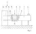
- the injection molding machine contains an injection unit 1, a clamping unit 2 and an injection molding tool 3 arranged between the two.
- the injection unit is of conventional construction and has, for example, a screw casting device, not shown, to which the plastic compound is fed via a filling funnel 4 and which presses the plasticized plastic mass into the tool 3 in the area of a stationary platen 5, which is provided with one or more openings for the sprue.
- unit 2 consists of a stationary part 2a and a movable platen 2b, which is mounted so that it can be moved back and forth parallel to the longitudinal axis 9 of the tool 3 by means of guides (not shown), the back and forth movement preferably using at least one cylinder / piston Arrangement 12 takes place, which has, for example, a piston rod 14 running parallel to the longitudinal axis 9 and fastened to the movable platen 2b and a cylinder 15 fastened to the fixed part 2a.
- the tool 3 has a die 6 and a core 7.
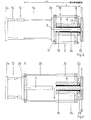
- the die 6 consists of a solid body which is provided with a flange 8 at its one end, which is assigned to the stationary clamping plate 5, can be moved back and forth parallel to its longitudinal axis 9 by means of guides, not shown, and one for Longitudinal axis 9 has coaxial, cylindrical and surrounded by a completely closed wall receiving opening 10.
- the receiving opening 10 serves for the coaxial receiving of the core 7, which has a smaller cross section than the receiving opening and is fastened with its end remote from the clamping plate 5 to a tool plate 11 which in turn is fastened to the movable clamping plate 2b of the clamping unit 2.
- the tool plate 11 lies against the die end remote from the stationary platen 5 and hermetically seals the mold cavity formed between the wall of the receiving opening 10 and the outer jacket of the core 7.
- two slides 16 are arranged, which can be moved back and forth perpendicular to the longitudinal axis 9 in opposite directions, as indicated by an arrow 17 (Fig. 2).
- the two slides 16 are expedient by means of guides (not shown) on the stationary platen 5 gel.ay
- the two sliders 16 are designed such that, in the closed position shown in FIGS. 2 to 4, they together with the core 7 delimit a cavity which extends the core 7 and the die 6 formed mold cavity.
- the mutually facing ends of the slider 16 each have e.g. annular recess 18 (Fig. 5), which forms a bead-like widening compared to the rest of the mold cavity.
- the closing force at the end of the die 6 assigned to the receiving plate 5 is applied in the radial direction by elements of the drive device, not shown and acting on the slider 16, which are expediently arranged on the clamping plate 5.
- the die can be formed by at least one further cylinder / piston arrangement 19, which is preferably part of the tool and consists, for example, of a piston rod 20 arranged parallel to the longitudinal axis 9 and fastened to the tool plate 11 and a cylinder 21 fastened to the flange 8 of the die 6 6 can be moved back and forth parallel to the longitudinal axis 9 relative to the tool plate 11.
- the tool and machine are first closed.
- the cylinder / piston arrangement 12 moves the movable platen 2b and the tool plate 11 screwed to it in the direction of the stationary platen 5.
- the tool plate 11 pushes the die 6 arranged in front of it until the one shown in FIG. 2 End position is reached, while at the same time the slider 16 are brought in the direction of arrows 23 (Fig. 3 and 4) in their near-axis closed position.
- the cylinder-piston arrangement 12 these are now required Lichen closing pressures at the two ends of the cavity limited by the die 6, the core 7, the slide 8 and the platen 5 applied.
- the injection process is then initiated by introducing the plasticized plastic compound into the mold cavity through at least one sprue opening provided in the clamping plate 5 and ending in the region of the part of the mold cavity delimited by the slides 16.
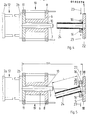
- the machine opens, ie the cylinder / piston arrangement 12 moves the movable platen 2b in the direction of the stationary part 2a. It takes the tool plate 11 screwed to it and pulls the core 7 out of the die according to FIG. 3.
- the die 6 is still pressed against the stationary platen 5 by the now pressurized cylinder / piston arrangement 19 and does not change its position.
- the tube 24 change its position, since the not yet demolded slides 16 engage in the area of their recesses 18 behind the widening 26 of the tube 24 acting as an undercut and prevent its axial displacement.
- the movement of the core 7 is interrupted as soon as its free end has left the die 6.
- the die 6 is stripped from the tube 24 in the next method step, whereby it moves in the same direction as the core 7, i.e. 4 is moved to the left.
- the die 6 is guided parallel to its longitudinal axis 9 in guides, not shown, so that even during this movement it can practically not come into contact with the tube 24, which is reduced in cross-section by shrinkage and held coaxially by the slider 16.
- the die 6 is pulled over the now fixed core 7, which penetrates into the receiving opening 10. The displacement of the die 6 is ended as soon as the free pipe end has left the die 6.
- the slides 16 are now moved radially away from the tube 24 in the direction of arrows 27 (FIG. 5).
- the holding section 25 is released so that the tube 24 falls down or can be removed from the machine by hand.
- the holding portion 25 is now cut off or otherwise removed from the tube 24, so that it now only consists of the section formed by the die 6 and the core 7 and therefore no longitudinal seams or transverse seams, but a smooth, shiny and undamaged surface.
- the individual process stages are carried out largely automatically with the aid of the drive mechanism and the control device, by the piston / cylinder arrangements 12 and 19 and the elements acting on the slide 16 correspondingly to be controlled.
- the piston / cylinder arrangements 12 and 19 are carried out largely automatically with the aid of the drive mechanism and the control device, by the piston / cylinder arrangements 12 and 19 and the elements acting on the slide 16 correspondingly to be controlled.
- the previously extended piston rod 14 is pulled into the cylinder 15 until the movable platen 2b assumes the end position shown in FIG. 3.
- the piston 21 is pressurized on its side facing away from the piston rod, so that the die is still held securely in its previous spray-side end position until the core 7 has left the die 6 and the tube 24.
- a hand or foot switch is preferably provided so that the tube 24 does not automatically fall down and is damaged in the process, but rather can first be gripped by the operator after opening the machine and then removed in a controlled manner after the switch has been actuated.
- the template contains according to Fig. 2 to 5 only one receiving aperture 10.
- a die body with a plurality of, for example, which are each associated with a core and a corresponding pair of slides 1 6. All cores 7 can be attached to the component 11 and all slides 16 can be mounted on the platen 5. Since only relatively small closing forces have to be applied because of the closed shape of the receiving openings 10, several tubes could be produced in one shot in this way.
- the die 6 expediently has a radially inwardly projecting holding projection 29 at its end remote from the clamping plate 5 (FIG. 6), which is expediently designed as an annular collar in the manufacture of hollow cylindrical tubes.
- the holding projection 29 has the effect that it has the end face removed from the holding section of the tube 24 engages and holds the tube 24 when pulling the core 7.
- the holding projection 29 could also be used instead of the holding section 25 for holding the tube 24, both the holding section 25 and the holding projection 29 are expediently provided in the production of long tubes in order to provide impressions in the region of the end face of the tube or axial compression of the tube to avoid pulling the core.
- the wall of the receiving opening 10 is appropriately rounded at its end assigned to the receiving plate 5, as indicated in FIG. 6 by the reference numeral 30.
- This measure serves the purpose of avoiding damage to the pipe surface even in the event that the pipe 24 should not remain exactly in its coaxial position when the die is stripped off.
- the method according to the invention takes advantage of the fact that, due to the temperature conditions in the mold cavity, at least at the end of the tube remote from the clamping plate 5, there is a slight opening which could serve as a guide when stripping the die and thereby prevents the The die grinds on the pipe surface.
- the invention is not restricted to the exemplary embodiment described, which can be modified in many ways.
- tubes with a cylindrical cross section tubes with other cross sections can be produced.
- the tube would gradually be pushed out of the die as soon as one end face lies against the projection extended after the core has been drawn and the die is pushed further over the core.
- a vertical could also be used arrangement of the tool can be provided.
- a stationary and a movable slider could be provided, in which case the tube would be provided with a holding section which only has a semi-annular bead. It is also possible to provide the slider with a bead-shaped projection instead of a recess and thereby to form a holding section which has an annular groove. This would also create a positive connection between the tube and the slides in the direction of the longitudinal axis 9, which axially fixes the tube when the core is pulled out.
- FIGS. 2 and 5 A particular advantage of the injection molding machine with tool according to the invention results from FIGS. 2 and 5, in which the length of the pipe to be manufactured is indicated by the reference symbol "L".
- L the length of the pipe to be manufactured
- a space which is slightly larger than twice the length "L” is sufficient for the movements of the core 7 or the die 6. Since the core and the die are only displaced by a distance corresponding to the length "L" for the purpose of demolding, and the displacement movement takes place in the same direction for both parts, the space requirement is minimal.
- the invention also relates to the production of pipes which are not only long but also thin-walled and have a diameter-wall thickness ratio of at least about 7: 1.
Landscapes
- Engineering & Computer Science (AREA)
- Manufacturing & Machinery (AREA)
- Mechanical Engineering (AREA)
- Moulds For Moulding Plastics Or The Like (AREA)
- Injection Moulding Of Plastics Or The Like (AREA)
Applications Claiming Priority (2)
| Application Number | Priority Date | Filing Date | Title |
|---|---|---|---|
| DE3443723 | 1984-11-30 | ||
| DE3443723A DE3443723C2 (de) | 1984-11-30 | 1984-11-30 | Verfahren und Vorrichtung zum Herstellen eines Kunststoff-Körpers mit wenigstens einem langen Rohr ohne Konizität |
Publications (3)
| Publication Number | Publication Date |
|---|---|
| EP0183278A2 true EP0183278A2 (fr) | 1986-06-04 |
| EP0183278A3 EP0183278A3 (en) | 1988-03-09 |
| EP0183278B1 EP0183278B1 (fr) | 1991-06-12 |
Family
ID=6251583
Family Applications (1)
| Application Number | Title | Priority Date | Filing Date |
|---|---|---|---|
| EP85115205A Expired - Lifetime EP0183278B1 (fr) | 1984-11-30 | 1985-11-30 | Procédé et dispositif pour fabrication de tuyau en matière plastique longue par moulage par injection |
Country Status (2)
| Country | Link |
|---|---|
| EP (1) | EP0183278B1 (fr) |
| DE (2) | DE3443723C2 (fr) |
Cited By (8)
| Publication number | Priority date | Publication date | Assignee | Title |
|---|---|---|---|---|
| EP0269217A3 (en) * | 1986-11-24 | 1989-11-29 | Johnson Controls, Inc. | Method of injection moulding and plastic part formed thereby |
| EP0654338A4 (fr) * | 1993-04-28 | 1996-08-07 | Nippon Petrochemicals Co Ltd | Corps cylindrique et procede pour son moulage par injection. |
| WO1996024480A1 (fr) * | 1995-02-09 | 1996-08-15 | Unique Mould Makers Limited | Jupe moulee sans ligne de jointure et procede de fabrication |
| EP0808703A3 (fr) * | 1996-05-20 | 1998-08-05 | SORENSEN, Jens Ole | Dispositif et méthode d'éjection de pièces moulées |
| EP1113338A3 (fr) * | 1999-12-27 | 2002-03-06 | Bridgestone Corporation | Tube en resin, procédé de production, support pour tambour photosensible, tambour photosensible à partir de ce support |
| FR2817793A1 (fr) * | 2000-12-12 | 2002-06-14 | Eurotube | Moule d'injection d'une ebauche de tube de conditionnement et procede de fabrication d'un tel tube |
| CN102922677A (zh) * | 2012-11-23 | 2013-02-13 | 昆山博爱模具开发有限公司 | 一种喷管模具 |
| US20150344689A1 (en) * | 2012-12-19 | 2015-12-03 | Invista North America S.A.R.L. | Thermoplastic polyamide components, and compositions and methods for their production and installation |
Families Citing this family (2)
| Publication number | Priority date | Publication date | Assignee | Title |
|---|---|---|---|---|
| DE3825489A1 (de) * | 1988-07-27 | 1990-02-01 | Glocker Raymond | Verfahren zum herstellen von duennwandigen rohren mit einem anschlusselement durch spritzguss |
| DE102019102709A1 (de) * | 2019-02-04 | 2020-08-06 | BE Technologie GmbH | Verfahren zur Herstellung von Kunststoffrohren |
Family Cites Families (3)
| Publication number | Priority date | Publication date | Assignee | Title |
|---|---|---|---|---|
| FR1066799A (fr) * | 1952-11-25 | 1954-06-09 | Tube pour matières pâteuses ou autres, procédé de fabrication de ce tube et moule pour la mise en oeuvre du procédé ou procédé similaire | |
| FR1203501A (fr) * | 1957-08-20 | 1960-01-19 | Procédé de moulage d'objets tubulaires en matière plastique, fermés à une extrémité, et outillage pour la mise en oeuvre de ce procédé | |
| DE1158239B (de) * | 1961-09-07 | 1963-11-28 | Krauss Maffei Ag | Verfahren und Vorrichtung zum Herstellen von Kunststoffrohren |
-
1984
- 1984-11-30 DE DE3443723A patent/DE3443723C2/de not_active Expired
-
1985
- 1985-11-30 DE DE8585115205T patent/DE3583216D1/de not_active Expired - Fee Related
- 1985-11-30 EP EP85115205A patent/EP0183278B1/fr not_active Expired - Lifetime
Cited By (9)
| Publication number | Priority date | Publication date | Assignee | Title |
|---|---|---|---|---|
| EP0269217A3 (en) * | 1986-11-24 | 1989-11-29 | Johnson Controls, Inc. | Method of injection moulding and plastic part formed thereby |
| EP0654338A4 (fr) * | 1993-04-28 | 1996-08-07 | Nippon Petrochemicals Co Ltd | Corps cylindrique et procede pour son moulage par injection. |
| US5759647A (en) * | 1993-04-28 | 1998-06-02 | Nippon Petrochemicals Co., Ltd. | Tubular article method for injection molding thereof |
| WO1996024480A1 (fr) * | 1995-02-09 | 1996-08-15 | Unique Mould Makers Limited | Jupe moulee sans ligne de jointure et procede de fabrication |
| EP0808703A3 (fr) * | 1996-05-20 | 1998-08-05 | SORENSEN, Jens Ole | Dispositif et méthode d'éjection de pièces moulées |
| EP1113338A3 (fr) * | 1999-12-27 | 2002-03-06 | Bridgestone Corporation | Tube en resin, procédé de production, support pour tambour photosensible, tambour photosensible à partir de ce support |
| FR2817793A1 (fr) * | 2000-12-12 | 2002-06-14 | Eurotube | Moule d'injection d'une ebauche de tube de conditionnement et procede de fabrication d'un tel tube |
| CN102922677A (zh) * | 2012-11-23 | 2013-02-13 | 昆山博爱模具开发有限公司 | 一种喷管模具 |
| US20150344689A1 (en) * | 2012-12-19 | 2015-12-03 | Invista North America S.A.R.L. | Thermoplastic polyamide components, and compositions and methods for their production and installation |
Also Published As
| Publication number | Publication date |
|---|---|
| DE3443723C2 (de) | 1987-03-12 |
| EP0183278A3 (en) | 1988-03-09 |
| DE3583216D1 (de) | 1991-07-18 |
| DE3443723A1 (de) | 1986-06-05 |
| EP0183278B1 (fr) | 1991-06-12 |
Similar Documents
| Publication | Publication Date | Title |
|---|---|---|
| DE3639313C2 (fr) | ||
| DE2336789C3 (de) | Verfahren und Werkzeug zur Entformung eines Kerns aus einem hinterschnittenen Kanalprofil aus Kunststoff | |
| DE3027087C2 (de) | Spritzgußvorrichtung sowie damit herstellbarer Sonnenenergiekollektor | |
| EP0630734B1 (fr) | Procédé de démoulage de corps creux moulés par injection avec des contre-dépouilles dans le contour interne et noyau associé | |
| DE1479374A1 (de) | Werkzeug mit verstellbarer Form zum Spritzen,Giessen und Pressen von hohlen Gegenstaenden | |
| EP2925468B1 (fr) | Noyau éclipsable et demi-moule équipé dudit noyau | |
| DE2619064A1 (de) | Spreizkern fuer die herstellung von spritzteilen | |
| DE1602291C3 (de) | Dornwechselvorrichtung an einer Metallstrangpresse | |
| EP0183278B1 (fr) | Procédé et dispositif pour fabrication de tuyau en matière plastique longue par moulage par injection | |
| EP3401037A1 (fr) | Moule destiné à la fabrication d'un noyau de coulé | |
| DE4318014C1 (de) | Kartusche für pastöse Massen sowie Verfahren und Vorrichtung zur Herstellung einer Kartusche | |
| EP0114570B1 (fr) | Dispositif de boudinage d'un profil creux | |
| DE2544894C2 (de) | Formschließeinrichtung für eine Kunststoff-Spritzgießmaschine | |
| DE1901009B1 (de) | Druckgiessmaschine zum umgiessen von blekpaketen insbeson dere fuer elektrische motore | |
| DE1045639B (de) | Spritzgussform zum Herstellen von Formkoerpern aus thermoplastischem Kunststoff, insbesondere Verschlusskappen fuer pharmazeutische Tablettenroehrchen | |
| DE2536142A1 (de) | Einrichtung zur handhabung von rotoren von elektromotoren und zum spritzgiessen von aluminiumkaefigwicklungen | |
| DE2619066C3 (de) | Formkern für ein Formwerkzeug | |
| DE19511712C1 (de) | Vorrichtung zum Transportieren eines Vorformlings von dem Schlauchkopf zu der Blasform einer Blasmaschine | |
| DE19536759C2 (de) | Verfahren zur Herstellung eines Rohrs | |
| WO2007062973A1 (fr) | Procede et systeme pour post-traitement de preformes | |
| DE2225123C3 (de) | Vorrichtung zum Verformen von Rohrenden aus einem thermoplastischen Kunststoff | |
| EP0043025A1 (fr) | Presse pour le filage indirect de métaux et appareil pour enlever des billettes "gelées" | |
| DE2249065C3 (de) | Vorrichtung zum Auswerfen eines Hohlkörpers aus einer Spritzblasmaschine | |
| WO2018103907A1 (fr) | Dispositif et procédé pour la fabrication d'objets à partir d'une matière à mouler durcissable à l'aide d'un dispositif coulissant | |
| DE2753202C2 (de) | Spritzblasformmaschine zum Herstellen eines flaschenförmigen Behälters |
Legal Events
| Date | Code | Title | Description |
|---|---|---|---|
| PUAI | Public reference made under article 153(3) epc to a published international application that has entered the european phase |
Free format text: ORIGINAL CODE: 0009012 |
|
| AK | Designated contracting states |
Kind code of ref document: A2 Designated state(s): DE FR GB |
|
| PUAL | Search report despatched |
Free format text: ORIGINAL CODE: 0009013 |
|
| AK | Designated contracting states |
Kind code of ref document: A3 Designated state(s): DE FR GB |
|
| 17P | Request for examination filed |
Effective date: 19880812 |
|
| 17Q | First examination report despatched |
Effective date: 19900523 |
|
| GRAA | (expected) grant |
Free format text: ORIGINAL CODE: 0009210 |
|
| AK | Designated contracting states |
Kind code of ref document: B1 Designated state(s): DE FR GB |
|
| ET | Fr: translation filed | ||
| GBT | Gb: translation of ep patent filed (gb section 77(6)(a)/1977) | ||
| REF | Corresponds to: |
Ref document number: 3583216 Country of ref document: DE Date of ref document: 19910718 |
|
| PLBE | No opposition filed within time limit |
Free format text: ORIGINAL CODE: 0009261 |
|
| STAA | Information on the status of an ep patent application or granted ep patent |
Free format text: STATUS: NO OPPOSITION FILED WITHIN TIME LIMIT |
|
| 26N | No opposition filed | ||
| PGFP | Annual fee paid to national office [announced via postgrant information from national office to epo] |
Ref country code: FR Payment date: 20001127 Year of fee payment: 16 |
|
| PGFP | Annual fee paid to national office [announced via postgrant information from national office to epo] |
Ref country code: GB Payment date: 20001129 Year of fee payment: 16 |
|
| PGFP | Annual fee paid to national office [announced via postgrant information from national office to epo] |
Ref country code: DE Payment date: 20010126 Year of fee payment: 16 |
|
| PG25 | Lapsed in a contracting state [announced via postgrant information from national office to epo] |
Ref country code: GB Free format text: LAPSE BECAUSE OF NON-PAYMENT OF DUE FEES Effective date: 20011130 |
|
| REG | Reference to a national code |
Ref country code: GB Ref legal event code: IF02 |
|
| PG25 | Lapsed in a contracting state [announced via postgrant information from national office to epo] |
Ref country code: DE Free format text: LAPSE BECAUSE OF NON-PAYMENT OF DUE FEES Effective date: 20020702 |
|
| GBPC | Gb: european patent ceased through non-payment of renewal fee |
Effective date: 20011130 |
|
| PG25 | Lapsed in a contracting state [announced via postgrant information from national office to epo] |
Ref country code: FR Free format text: LAPSE BECAUSE OF NON-PAYMENT OF DUE FEES Effective date: 20020730 |
|
| REG | Reference to a national code |
Ref country code: FR Ref legal event code: ST |
|
| REG | Reference to a national code |
Ref country code: FR Ref legal event code: ST |