EP0183308B1 - Conduit d'air - Google Patents
Conduit d'air Download PDFInfo
- Publication number
- EP0183308B1 EP0183308B1 EP85201856A EP85201856A EP0183308B1 EP 0183308 B1 EP0183308 B1 EP 0183308B1 EP 85201856 A EP85201856 A EP 85201856A EP 85201856 A EP85201856 A EP 85201856A EP 0183308 B1 EP0183308 B1 EP 0183308B1
- Authority
- EP
- European Patent Office
- Prior art keywords
- air duct
- plate
- slotted holes
- edges
- shaped element
- Prior art date
- Legal status (The legal status is an assumption and is not a legal conclusion. Google has not performed a legal analysis and makes no representation as to the accuracy of the status listed.)
- Expired
Links
- 238000010276 construction Methods 0.000 description 4
- 238000001035 drying Methods 0.000 description 4
- 239000000047 product Substances 0.000 description 4
- 238000001816 cooling Methods 0.000 description 3
- 239000000463 material Substances 0.000 description 3
- 244000291564 Allium cepa Species 0.000 description 1
- 235000002732 Allium cepa var. cepa Nutrition 0.000 description 1
- 244000061456 Solanum tuberosum Species 0.000 description 1
- 235000002595 Solanum tuberosum Nutrition 0.000 description 1
- 238000005452 bending Methods 0.000 description 1
- 239000006227 byproduct Substances 0.000 description 1
- 239000002184 metal Substances 0.000 description 1
- 235000012015 potatoes Nutrition 0.000 description 1
- 238000009423 ventilation Methods 0.000 description 1
Images


Classifications
-
- B—PERFORMING OPERATIONS; TRANSPORTING
- B65—CONVEYING; PACKING; STORING; HANDLING THIN OR FILAMENTARY MATERIAL
- B65D—CONTAINERS FOR STORAGE OR TRANSPORT OF ARTICLES OR MATERIALS, e.g. BAGS, BARRELS, BOTTLES, BOXES, CANS, CARTONS, CRATES, DRUMS, JARS, TANKS, HOPPERS, FORWARDING CONTAINERS; ACCESSORIES, CLOSURES, OR FITTINGS THEREFOR; PACKAGING ELEMENTS; PACKAGES
- B65D88/00—Large containers
- B65D88/74—Large containers having means for heating, cooling, aerating or other conditioning of contents
- B65D88/742—Large containers having means for heating, cooling, aerating or other conditioning of contents using ventilating sheaths
-
- F—MECHANICAL ENGINEERING; LIGHTING; HEATING; WEAPONS; BLASTING
- F26—DRYING
- F26B—DRYING SOLID MATERIALS OR OBJECTS BY REMOVING LIQUID THEREFROM
- F26B9/00—Machines or apparatus for drying solid materials or objects at rest or with only local agitation; Domestic airing cupboards
- F26B9/10—Machines or apparatus for drying solid materials or objects at rest or with only local agitation; Domestic airing cupboards in the open air; in pans or tables in rooms; Drying stacks of loose material on floors which may be covered, e.g. by a roof
- F26B9/103—Machines or apparatus for drying solid materials or objects at rest or with only local agitation; Domestic airing cupboards in the open air; in pans or tables in rooms; Drying stacks of loose material on floors which may be covered, e.g. by a roof using fixed or removable drying air channels placed in the stack, e.g. horizontally or vertically
Definitions
- the invention relates to a plate-shaped element provided with holes for the passage of air having a curved course in cross-section, thus forming two edges, and a corrugated course in longitudinal section, the element being intended to rest with its edges on the floor of a building so as to form an air duct.
- Such elements usually placed on the floor in a storage room, in such a manner that several such ducts, which can be built up from sections, are thereby arranged at some distance of and parallel to each other.
- Products to be dried, cooled and/or ventilated can then be brought into the storage room such, that said products are deposited in a heap above and between the air ducts.
- air can be supplied to the air ducts continuously or intermittently, which air, whether or not heated, can escape from the air duct via the passages in the plate-shaped element and stream along the products to be treated.
- the plate-shaped element is characterized in, that the holes are slotted holes, which are provided only in the tops of the corrugations in those portions of the plate-shaped element which join the edges of said plate-shaped element.
- Fig. 1 illustrates a few air ducts 2 located adjacent to each other on a bottom 1, which ducts have been arranged parallel to each other.
- the air ducts have, in cross section, curved, usually semicircular shape, whilst seen in longitudinal section an air duct has a corrugated course.
- the ducts are thereby made of metal sheet, but of course it will be conceivable to use other materials for this purpose, such as e.g. plastic material.
- An air duct can be made of a single plate-shaped part, but in particular with longer air ducts a duct will usually be built up from sections which overlap each other at their ends.
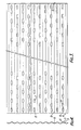
- Such an air duct or a section of an air duct can be formed by bending a corrugated sheet 3 as illustrated in figs. 3 and 4 around its longitudinal axis extending parallel to its boundary edges 4 and 5.
- slotted holes 7 have been provided in the tops 6 of the corrugations in the portions of the corrugated sheet joining the boundary edges 4 and 5 in such a manner that the longitudinal axes of said slotted holes coincide with the longitudinal axes of the corrugations and are therefore perpendicular to the boundary edges 4 and 5.
- no holes have been provided, as will be apparent from figs. 3 and 4.
- the slotted holes 7 located nearest to the boundary edges 4 and 5 lie in a line in the corrugation tops 6 located adjacent to each other, whilst the slotted holes located further away from the boundary edges 4 and 5 in a pair of adjacent corrugation tops 6, seen in the longitudinal direction of the boundary edges 4 and 5, are staggered relatively to each other. As a result of this a better spreading of the air coming out of the air duct via the slotted holes is achieved as well as a better resistance of the air duct to collapsing.
- the centre distance between a pair of rectangular slotted holes located in a corrugation top 6 will preferably be ⁇ 130 mm, except for those slotted holes which have been arranged comparatively, closely together near the secondary edges 4 and 5 as is illustrated in the figures and whereby the centre distance between said slotted holes is 65 mm.
- Fig. 5 shows a development of a plate-shaped portion, which can be used for making air ducts with smaller diameters e.g. between ⁇ 630 mm and 1025 mm.
- the centre distance between the slotted holes which for the rest have the same. length as in the first mentioned embodiment, has thereby been chosen smaller and is preferbaly 90 mm here.
- the centre distance between the slotted holes arranged closely together near the boundary lines 4 and 5 has thereby been kept equal to that of the embodiment discussed first.
- the width of the strip of the sheet joining a boundary edge 4 or 5 measured in the direction of the corrugations is preferably less than 1/20 of the width of the developed sheet illustrated in figs. 3 and 5 measured between the boundary edges 4 and 5.
Landscapes
- Engineering & Computer Science (AREA)
- Mechanical Engineering (AREA)
- General Engineering & Computer Science (AREA)
- Duct Arrangements (AREA)
- Measurement And Recording Of Electrical Phenomena And Electrical Characteristics Of The Living Body (AREA)
- Magnetic Resonance Imaging Apparatus (AREA)
- Fittings On The Vehicle Exterior For Carrying Loads, And Devices For Holding Or Mounting Articles (AREA)
- Drying Of Solid Materials (AREA)
- Branch Pipes, Bends, And The Like (AREA)
- Glass Compositions (AREA)
- Air-Flow Control Members (AREA)
Claims (6)
Priority Applications (1)
| Application Number | Priority Date | Filing Date | Title |
|---|---|---|---|
| AT85201856T ATE39568T1 (de) | 1984-11-14 | 1985-11-12 | Luftleitung. |
Applications Claiming Priority (2)
| Application Number | Priority Date | Filing Date | Title |
|---|---|---|---|
| NL8403473 | 1984-11-14 | ||
| NL8403473A NL8403473A (nl) | 1984-11-14 | 1984-11-14 | Luchtkanaal. |
Publications (2)
| Publication Number | Publication Date |
|---|---|
| EP0183308A1 EP0183308A1 (fr) | 1986-06-04 |
| EP0183308B1 true EP0183308B1 (fr) | 1988-12-28 |
Family
ID=19844764
Family Applications (1)
| Application Number | Title | Priority Date | Filing Date |
|---|---|---|---|
| EP85201856A Expired EP0183308B1 (fr) | 1984-11-14 | 1985-11-12 | Conduit d'air |
Country Status (6)
| Country | Link |
|---|---|
| EP (1) | EP0183308B1 (fr) |
| AT (1) | ATE39568T1 (fr) |
| DE (1) | DE3567092D1 (fr) |
| DK (1) | DK161040C (fr) |
| IE (1) | IE57254B1 (fr) |
| NL (1) | NL8403473A (fr) |
Families Citing this family (2)
| Publication number | Priority date | Publication date | Assignee | Title |
|---|---|---|---|---|
| FR2624690B1 (fr) * | 1987-12-16 | 1990-05-25 | Segers Bernard | Gaine de ventilation a debit d'air variable pour ventilation des cereales |
| CN114294912B (zh) * | 2022-01-07 | 2022-11-11 | 季华恒一(佛山)半导体科技有限公司 | 一种电加热式烘干系统 |
Family Cites Families (4)
| Publication number | Priority date | Publication date | Assignee | Title |
|---|---|---|---|---|
| US2196391A (en) * | 1936-01-21 | 1940-04-09 | Gronert August | Ventilating plant for goods piled up such as grain |
| US2818009A (en) * | 1955-08-05 | 1957-12-31 | Vincent B Steffen | Base for steel storage bin |
| US3054342A (en) * | 1959-10-01 | 1962-09-18 | Butler Manufacturing Co | Grain aeration structure |
| US3136240A (en) * | 1960-11-28 | 1964-06-09 | Frederick W Rabe | Cross-flow aeration system for grain bins |
-
1984
- 1984-11-14 NL NL8403473A patent/NL8403473A/nl not_active Application Discontinuation
-
1985
- 1985-11-12 DE DE8585201856T patent/DE3567092D1/de not_active Expired
- 1985-11-12 DK DK520585A patent/DK161040C/da not_active IP Right Cessation
- 1985-11-12 EP EP85201856A patent/EP0183308B1/fr not_active Expired
- 1985-11-12 AT AT85201856T patent/ATE39568T1/de not_active IP Right Cessation
- 1985-11-13 IE IE2836/85A patent/IE57254B1/en not_active IP Right Cessation
Also Published As
| Publication number | Publication date |
|---|---|
| EP0183308A1 (fr) | 1986-06-04 |
| ATE39568T1 (de) | 1989-01-15 |
| DK520585A (da) | 1986-05-15 |
| IE57254B1 (en) | 1992-06-17 |
| DK161040C (da) | 1991-10-28 |
| DE3567092D1 (en) | 1989-02-02 |
| DK161040B (da) | 1991-05-21 |
| NL8403473A (nl) | 1986-06-02 |
| IE852836L (en) | 1986-05-14 |
| DK520585D0 (da) | 1985-11-12 |
Similar Documents
| Publication | Publication Date | Title |
|---|---|---|
| US5217788A (en) | Corrugated sheet assembly | |
| USRE37388E1 (en) | Ridge cap type roof ventilator | |
| US3830684A (en) | Filling sheets for liquid-gas contact apparatus | |
| JP4125799B2 (ja) | 切溝付絶縁ボード | |
| US5651734A (en) | Ridge cap roof ventilator applied in roll form and method of use | |
| US5431980A (en) | Formable cellular material with synclastic behavior | |
| US4379381A (en) | Roof insulation system | |
| SK252692A3 (en) | Filling into apparatus in which different mediums are leading in contact | |
| JPS60243495A (ja) | 水用クーリングタワーのためのフイルム装填シートおよびフイルム装填パツク | |
| US4418558A (en) | Method of manufacture of ventilated sheet metal floor members | |
| US4805367A (en) | Ventilating support for roof insulation | |
| KR970706064A (ko) | 교차형 배열의 마이크로 조직을 갖춘 금속 벌집체(microstructures in an intersecting arrangement) | |
| EP0183308A1 (fr) | Conduit d'air | |
| US3815486A (en) | Air circulation diffuser system | |
| RU2154130C2 (ru) | Сопловой короб установки для сушки полотна волокнистого материала | |
| GB2174615A (en) | Matrix for a catalytic reactor for waste gas cleaning | |
| FI57536C (fi) | Anordning foer avskiljande av droppar ur gaser | |
| GB2106948A (en) | Metal floor-grating | |
| US5151151A (en) | Pleating machine for dual fluted shade | |
| KR20090004026A (ko) | 환기덕트용 전열교환기 소자 | |
| JPH11114734A (ja) | パイプ整列シート | |
| JPH0536367Y2 (fr) | ||
| EP1097296A1 (fr) | Structure double paroi d'un systeme de conduit de ventilation | |
| SU1704691A1 (ru) | Устройство дл сушки растительных материалов активным вентилированием | |
| EP0072639A2 (fr) | Séchoirs de grains |
Legal Events
| Date | Code | Title | Description |
|---|---|---|---|
| PUAI | Public reference made under article 153(3) epc to a published international application that has entered the european phase |
Free format text: ORIGINAL CODE: 0009012 |
|
| AK | Designated contracting states |
Kind code of ref document: A1 Designated state(s): AT BE CH DE FR GB IT LI LU NL SE |
|
| 17P | Request for examination filed |
Effective date: 19861128 |
|
| 17Q | First examination report despatched |
Effective date: 19871201 |
|
| GRAA | (expected) grant |
Free format text: ORIGINAL CODE: 0009210 |
|
| STAA | Information on the status of an ep patent application or granted ep patent |
Free format text: STATUS: THE PATENT HAS BEEN GRANTED |
|
| AK | Designated contracting states |
Kind code of ref document: B1 Designated state(s): AT BE CH DE FR GB IT LI LU NL SE |
|
| PG25 | Lapsed in a contracting state [announced via postgrant information from national office to epo] |
Ref country code: SE Effective date: 19881228 Ref country code: LI Effective date: 19881228 Ref country code: IT Free format text: LAPSE BECAUSE OF FAILURE TO SUBMIT A TRANSLATION OF THE DESCRIPTION OR TO PAY THE FEE WITHIN THE PRESCRIBED TIME-LIMIT;WARNING: LAPSES OF ITALIAN PATENTS WITH EFFECTIVE DATE BEFORE 2007 MAY HAVE OCCURRED AT ANY TIME BEFORE 2007. THE CORRECT EFFECTIVE DATE MAY BE DIFFERENT FROM THE ONE RECORDED. Effective date: 19881228 Ref country code: CH Effective date: 19881228 Ref country code: AT Effective date: 19881228 |
|
| REF | Corresponds to: |
Ref document number: 39568 Country of ref document: AT Date of ref document: 19890115 Kind code of ref document: T |
|
| REF | Corresponds to: |
Ref document number: 3567092 Country of ref document: DE Date of ref document: 19890202 |
|
| ET | Fr: translation filed | ||
| REG | Reference to a national code |
Ref country code: CH Ref legal event code: PL |
|
| PLBI | Opposition filed |
Free format text: ORIGINAL CODE: 0009260 |
|
| PG25 | Lapsed in a contracting state [announced via postgrant information from national office to epo] |
Ref country code: GB Effective date: 19891112 |
|
| 26 | Opposition filed |
Opponent name: TOLSMA TECHNIEK B.V. Effective date: 19890928 |
|
| NLR1 | Nl: opposition has been filed with the epo |
Opponent name: TOLSMA TECHNIEK B.V. |
|
| PLBG | Opposition deemed not to have been filed |
Free format text: ORIGINAL CODE: 0009274 |
|
| 26D | Opposition deemed not to have been filed | ||
| GBPC | Gb: european patent ceased through non-payment of renewal fee | ||
| NLXE | Nl: other communications concerning ep-patents (part 3 heading xe) |
Free format text: IN PAT.BUL.02/90:THE OPPOSITION SHOULD BE DEEMED NOT TO HAVE BEEN FILED |
|
| REG | Reference to a national code |
Ref country code: FR Ref legal event code: TP |
|
| NLS | Nl: assignments of ep-patents |
Owner name: INDUSTRIE EN HANDELMAATSCHAPPIJ BERGSCHENHOEK B.V. |
|
| EPTA | Lu: last paid annual fee | ||
| PGFP | Annual fee paid to national office [announced via postgrant information from national office to epo] |
Ref country code: BE Payment date: 20041015 Year of fee payment: 20 |
|
| PGFP | Annual fee paid to national office [announced via postgrant information from national office to epo] |
Ref country code: NL Payment date: 20041126 Year of fee payment: 20 |
|
| PGFP | Annual fee paid to national office [announced via postgrant information from national office to epo] |
Ref country code: FR Payment date: 20041129 Year of fee payment: 20 |
|
| PGFP | Annual fee paid to national office [announced via postgrant information from national office to epo] |
Ref country code: LU Payment date: 20041130 Year of fee payment: 20 |
|
| PGFP | Annual fee paid to national office [announced via postgrant information from national office to epo] |
Ref country code: DE Payment date: 20050126 Year of fee payment: 20 |
|
| PG25 | Lapsed in a contracting state [announced via postgrant information from national office to epo] |
Ref country code: NL Free format text: LAPSE BECAUSE OF EXPIRATION OF PROTECTION Effective date: 20051112 |
|
| BE20 | Be: patent expired |
Owner name: *INDUSTRIE EN HANDELMAATSCHAPPIJ BERGSCHENHOEK B.V Effective date: 20051112 |
|
| NLV7 | Nl: ceased due to reaching the maximum lifetime of a patent |
Effective date: 20051112 |
|
| RIN2 | Information on inventor provided after grant (corrected) |
Inventor name: ROOK, ADRIANUS |
|
| BE20 | Be: patent expired |
Owner name: *INDUSTRIE EN HANDELMAATSCHAPPIJ BERGSCHENHOEK B.V Effective date: 20051112 |