EP0183316A1 - Absorptions-Resorptionswärmepumpe - Google Patents
Absorptions-Resorptionswärmepumpe Download PDFInfo
- Publication number
- EP0183316A1 EP0183316A1 EP85201904A EP85201904A EP0183316A1 EP 0183316 A1 EP0183316 A1 EP 0183316A1 EP 85201904 A EP85201904 A EP 85201904A EP 85201904 A EP85201904 A EP 85201904A EP 0183316 A1 EP0183316 A1 EP 0183316A1
- Authority
- EP
- European Patent Office
- Prior art keywords
- circuit
- resorber
- desorber
- evaporator
- conduit
- Prior art date
- Legal status (The legal status is an assumption and is not a legal conclusion. Google has not performed a legal analysis and makes no representation as to the accuracy of the status listed.)
- Granted
Links
- 239000007788 liquid Substances 0.000 claims abstract description 45
- 239000006096 absorbing agent Substances 0.000 claims abstract description 37
- 239000000126 substance Substances 0.000 claims abstract description 17
- 230000007246 mechanism Effects 0.000 claims abstract description 10
- 239000000203 mixture Substances 0.000 description 16
- QGZKDVFQNNGYKY-UHFFFAOYSA-N Ammonia Chemical compound N QGZKDVFQNNGYKY-UHFFFAOYSA-N 0.000 description 12
- 229910000069 nitrogen hydride Inorganic materials 0.000 description 8
- XLYOFNOQVPJJNP-UHFFFAOYSA-N water Substances O XLYOFNOQVPJJNP-UHFFFAOYSA-N 0.000 description 8
- 239000012071 phase Substances 0.000 description 5
- 238000010521 absorption reaction Methods 0.000 description 4
- 239000007789 gas Substances 0.000 description 4
- 239000007791 liquid phase Substances 0.000 description 4
- AMXOYNBUYSYVKV-UHFFFAOYSA-M lithium bromide Chemical compound [Li+].[Br-] AMXOYNBUYSYVKV-UHFFFAOYSA-M 0.000 description 4
- 238000010438 heat treatment Methods 0.000 description 3
- 239000011149 active material Substances 0.000 description 2
- 229910021529 ammonia Inorganic materials 0.000 description 2
- 239000010842 industrial wastewater Substances 0.000 description 2
- VNWKTOKETHGBQD-UHFFFAOYSA-N methane Chemical compound C VNWKTOKETHGBQD-UHFFFAOYSA-N 0.000 description 2
- JIAARYAFYJHUJI-UHFFFAOYSA-L zinc dichloride Chemical compound [Cl-].[Cl-].[Zn+2] JIAARYAFYJHUJI-UHFFFAOYSA-L 0.000 description 2
- 239000013543 active substance Substances 0.000 description 1
- 230000007423 decrease Effects 0.000 description 1
- 238000003795 desorption Methods 0.000 description 1
- 238000005259 measurement Methods 0.000 description 1
- 239000003345 natural gas Substances 0.000 description 1
- 238000011144 upstream manufacturing Methods 0.000 description 1
- 235000005074 zinc chloride Nutrition 0.000 description 1
- 239000011592 zinc chloride Substances 0.000 description 1
- IPCXNCATNBAPKW-UHFFFAOYSA-N zinc;hydrate Chemical compound O.[Zn] IPCXNCATNBAPKW-UHFFFAOYSA-N 0.000 description 1
Images
Classifications
-
- F—MECHANICAL ENGINEERING; LIGHTING; HEATING; WEAPONS; BLASTING
- F25—REFRIGERATION OR COOLING; COMBINED HEATING AND REFRIGERATION SYSTEMS; HEAT PUMP SYSTEMS; MANUFACTURE OR STORAGE OF ICE; LIQUEFACTION SOLIDIFICATION OF GASES
- F25B—REFRIGERATION MACHINES, PLANTS OR SYSTEMS; COMBINED HEATING AND REFRIGERATION SYSTEMS; HEAT PUMP SYSTEMS
- F25B15/00—Sorption machines, plants or systems, operating continuously, e.g. absorption type
- F25B15/12—Sorption machines, plants or systems, operating continuously, e.g. absorption type with resorber
-
- Y—GENERAL TAGGING OF NEW TECHNOLOGICAL DEVELOPMENTS; GENERAL TAGGING OF CROSS-SECTIONAL TECHNOLOGIES SPANNING OVER SEVERAL SECTIONS OF THE IPC; TECHNICAL SUBJECTS COVERED BY FORMER USPC CROSS-REFERENCE ART COLLECTIONS [XRACs] AND DIGESTS
- Y02—TECHNOLOGIES OR APPLICATIONS FOR MITIGATION OR ADAPTATION AGAINST CLIMATE CHANGE
- Y02A—TECHNOLOGIES FOR ADAPTATION TO CLIMATE CHANGE
- Y02A30/00—Adapting or protecting infrastructure or their operation
- Y02A30/27—Relating to heating, ventilation or air conditioning [HVAC] technologies
-
- Y—GENERAL TAGGING OF NEW TECHNOLOGICAL DEVELOPMENTS; GENERAL TAGGING OF CROSS-SECTIONAL TECHNOLOGIES SPANNING OVER SEVERAL SECTIONS OF THE IPC; TECHNICAL SUBJECTS COVERED BY FORMER USPC CROSS-REFERENCE ART COLLECTIONS [XRACs] AND DIGESTS
- Y02—TECHNOLOGIES OR APPLICATIONS FOR MITIGATION OR ADAPTATION AGAINST CLIMATE CHANGE
- Y02B—CLIMATE CHANGE MITIGATION TECHNOLOGIES RELATED TO BUILDINGS, e.g. HOUSING, HOUSE APPLIANCES OR RELATED END-USER APPLICATIONS
- Y02B30/00—Energy efficient heating, ventilation or air conditioning [HVAC]
- Y02B30/62—Absorption based systems
Definitions
- the invention relates to an absorption-resorption heat pump comprising a first circuit including a desorber and an absorber interconnected by conduits having a heat exchanger provided therein, so that a first circulatory flow of a first system of liquid substances can be maintained by suitable means from the desorber to the absorber via one of the conduits and from the absorber to the desorber via another one of these conduits, and a second circuit including a resorber or condenser and an evaporator likewise interconnected by conduits having a heat exchanger provided therein, so that a second circulatory flow of a second system of essentially similar liquid substances can be maintained by suitable means from the evaporator to the resorber or condenser to the evaporator via another one of these conduits, the desorber of the first circuit being connected through a conduit for a volatile component of the first system of substances to the resorber or condensor of the second circuit and the evaporator of the second circuit being connected through a conduit for a
- Such a heat pump is known from European patent application 0,054,719.
- Essential for such an absorption- desorption heat pump is the presence of two circulatory circuits through which suitable systems of substances circulates. Suitable systems are, inter alia, a mixture of lithium bromide and water, a mixture of 50% of lithium bromide and 50% of zinc chloride and water, and a mixture of ammonia (NH 3 ) and water.
- the two circulatory circuits in the heat pump are separated from each other in principle in the liquid phase and are connected with each other in the vapour phase. During operation of the heat pump, the concentrations of the components in the circulatory flows will differ from each other.
- the volatile component of the system of substances has the lowest concentrations.
- the primary energy is applied to the circulatory flow, which may be called the poor flow in view of the low concentration of volatile component therein as compared with the average concentration, as a result of which this poor flow is further depleted by the expulsion of the volatile component in the vapour phase.
- the gas flow of thus-expelled volatile component is passed to the resorber in the second circulatory circuit, in which resorber a slightly lower pressure is maintained.
- the volatile component is absorbed into the second circulatory flow, which may be called the rich flow in view of the concentration of volatile component therein.
- the rich flow is thus further enriched, while the absorption results in the evolution of heat, which heat may be used for some purpose.
- the enriched rich flow is passed from the resorber to the evaporator. Upstream of this evaporator, the flow is caused to expand so that it flashes spontaneously.
- flashing is understood the creation of a vapour phase, the heat required for which is withdrawn from the latent heat of the circulatory flow.
- a vapour phase is produced in the evaporator, while the rich flow is depleted and cools down.
- the rich flow is even further depleted by the application of secondary energy, such as geothermal heat, heat from the atmosphere or from industrial waste water, or solar energy.
- the low pressure vapour phase is passed from the evaporator to the absorber in the first circulatory circuit and is there absorbed into a depleted poor circulatory flow with the evolution of heat, which heat may be used for some purpose.
- the depleted poor first circulatory flow itself is passed from the desorber to the absorber while undergoing a pressure drop. As a small amount of volatile component is present, this will usually not be attended by flashing.
- Each one of the circulatory circuits includes a heat exchanger in which the latent heat of the outgoing flow is transferred to the incoming flow in the same circulatory circuit.
- the prior art device is provided with a branch conduit connecting to a control valve included in the conduit between the evaporator and the resorber, which branch conduit opens into a rectifying column connected to the desorber.
- the control valve in the prior art device is operated in dependence upon the pressure in the resorber and hence in dependence upon the temperature there. The realization of such operation requires a considerable amount of control equipment.
- This object is achieved by means of a device in which a storage vessel is provided at a point downstream of the heat exchanger in that section of the second circuit where liquid passes from the evaporator to the resorber, which storage vessel includes an overflow mechanism, and the branch conduit is connected to this overflow mechanism.
- the storage vessel of the device according to the invention may conveniently be part of or be fitted within the resorber.
- the concentrations of the solutions in both circuits it should be possible for the concentrations of the solutions in both circuits to vary in order to allow an optimum heat ratio to be obtained under varying circumstances.
- One possibility for achieving such variability of the concentrations is to so dimension all containers of the device that the level of the solution can vary.
- the vapour formed in the desorber has a lower concentration of active substance than the vapour formed in the evaporator, an interruption in the flow from the resorption section back to the absorption section results in an increase in the level of the solution in the resorber and the evaporator and an increase in the concentration in the circulatory circuit of the desorber and the absorber, while the concentration in the circuit of the resorber and the evaporator decreases.
- the concentrations vary in opposite sense.
- the volume of the various containers of the device should be so large that relatively large variations in the amount of liquid in each container can be realized.
- the bringing about of the desired variations requires the making of level measurements. The control mechanisms needed therefor complicate the device.
- the device according to the invention it is possible to realize variations in the concentrations throughout a wide range without altering the levels in the different containers as the two circuits are provided with containers in which part of the liquid circulating in the respective circuit can be stored, so that this part is temporarily kept from circulating.
- Such an embodiment permits a control with simple level switches or overflow mechanisms.
- one of the containers is adapted to store liquid rich in active material while the other container is adapted to store liquid poor in active material.
- the containers are so mounted that one is connected with the conduit for the liquid of higher active component concentration and the other is connected with the conduit for the liquid of lower active component concentration.
- one of the containers can be conveniently connected to either the evaporator or the resorber or the conduit through which the liquid passes from the resorber to the evaporator, and the other container can be connected to either the absorber or the desorber or the conduit through which the liquid passes from the desorber to the absorber.
- concentrations of the circulating liquids to be varied as either a greater amount of liquid can be stored in one container or a greater amount of liquid can be stored in the other, so that the amount of liquid circulating remains constant even when the concentrations vary.
- the containers may be connected parallel to the absorber and the evaporator, respectively. Then the inlet conduits of the containers are connected to the conduit passing liquid from the desorber to the absorber and the conduit passing liquid from the resorber to the evaporator, respectively, and the outlet conduits of the containers are connected to the outlet of the absorber and the outlet of the evaporator, respectively.
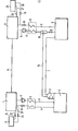
- the device comprises a first circulatory circuit including an absorber 1 and a desorber 2.
- Absorber 1 and desorber 2 are interconnected by a pair of conduits 3 and 4.
- Conduits 3 and 4 extend through a heat exchanger 5 in which the liquid passing through conduit 3 can give up heat to the liquid passing through conduit 4.
- Conduit 3 has a pump 6 therein for causing a liquid to circulate through the first circuit, which liquid usually consists of a mixture of an essentially liquid substance with a more volatile component.
- the mixture of substances passes through conduit 3 to enter desorber 2.
- Energy is being applied to desorber 2, for example by means of a gas burner. As a result, a large portion of the volatile component escapes from the mixture.
- This relatively high pressure gaseous component is passed through a conduit 7 to a resorber 8 included in a second circulatory circuit.
- resorber 8 the volatile component is resorbed into the flow passing through this resorber, which flow consists of a similar mixture of substances as that flowing in the first circulatory circuit but is already relatively rich in that volatile component.
- a rich flow is passed out from resorber 8 through conduit 9, which flow is processed in a manner to be described later on.
- the circulatory flow heated in desorber 2 is passed via conduit 4 through heat exchanger 5, where heat is given up to the flow in conduit 3, to reach absorber 1 via a release valve 10.
- release valve 10 By means of release valve 10 a substantial pressure drop is realized, so that the pressure in absorber 1 is far lower than that in desorber 2.
- absorber 1 absorption of volatile component into the liquid phase takes place, so that the liquid flow from absorber 1 through conduit 3 is richer than the flow passing through conduit 4 to absorber 1.
- volatile component passed from an evaporator 12 through a conduit 11 to absorber 1 is absorbed there into the liquid phase.
- the absorption heat evolved in absorber 1 is discharged for use for some purpose.
- the second circulatory circuit of the device according to the invention includes resorber 8 and evaporator 12, which are interconnected by conduits 9 and 13.
- a rich liquid flow is passed by the pump 14 via the heat exchanger 15 to resorber 8, where this flow is further enriched by the inclusion therein of volatile component passed to resorber 8 through conduit 7.
- the evolving heat is discharged from resorber 8 for use for some purpose.
- the enriched flow is passed from resorber 8 through conduit 9 via the heat exchanger 15 to the release valve 16.
- the flow through conduit 9 can give up heat to the flow through conduit 13.
- release valve 16 a release of pressure of the enriched liquid flow takes place, causing the mixture to flash.
- the pressure in evaporator 12 is therefore relatively low.
- a source that is normally not suitable for heating purposes may be used as a source of secondary energy.
- secondary energy are geothermal energy, heat from the atmosphere, heat from industrial waste water and solar energy. In the device according to the invention this secondary energy is boosted to a useful level in resorber 8 and absorber 1, respectively.
- Conduit 7 passing the liquid phase from desorber 2 to resorber 8 may have its end facing desorber 2 connected either directly to this desorber or to a rectifying column 17 coupled with desorber 2.
- the circuit of resorber 8 and evaporator 12 includes a storage vessel 18 having an overflow mechanism.
- storage vessel 18 is located in conduit 13 at a point downstream of heat exchanger 15, or this vessel is part of resorber 8 or is fitted therein.
- a branch conduit 19 extends from storage vessel 18 to desorber 2. As shown, this conduit 19 may be connected to rectifying column 17. The extent of the enrichment and depletion of the liquid flows in the two circuits, i.e., the concentrations of the volatile component in the liquid flows, can be controlled by means of storage vessel 18, branch conduit 19 and a valve 20 without complex control equipment being required.
- the two circulatory circuits are further provided with containers in which part of the liquid circulating in the respective circuit can be stored.
- the container 21 is connected through the conduit 22 to absorber 1 and through the conduit 23 to the conduit passing liquid from desorber 2 to absorber 1.
- Control valves 24 and 25 are included in conduits 22 and 23, respectively, for permitting a control of the storage in container 21.
- the container 26 is connected through the conduit 27 to evaporator 12 and through the conduit 28 to the conduit passing liquid from resorber 8 to evaporator 12.
- Control valves 29 and 30 are included in conduits 27 and 28, respectively, for permitting a control of the storage in container 26.
- a mixture consisting of ammonia and water
- Such a mixture is, for example, heated in desorber 2 by means of a natural gas burner.
- NH 3 gas will escape from the liquid having a temperature of approximately 130°C.
- the pressure in desorber 2 is then approximately 5 atmospheres.
- a mixture of water with only 10% of NH 3 is passed out through conduit 4.
- This mixture is enriched in absorber 1 at 1 atmosphere.
- the enriched mixture (water with 20% of NH 3 ) is passed to desorber 2.
- NH 3 gas is absorbed by the liquid flow in resorber 8.
- the pressure is 5 atmospheres and the temperature is 45°C, suitable for use in a central heating system.
- the rich mixture water with 55% of NH 3
- the temperature of the mixture has dropped to.approximately O O C.
- a reasonable amount of NH 3 can yet be expelled from the mixture by the application of secondary energy thereto.
- a flow of water with approximately 45% of NH 3 passes out of evaporator 12 to resorber 8.
Landscapes
- Engineering & Computer Science (AREA)
- Physics & Mathematics (AREA)
- Mechanical Engineering (AREA)
- Thermal Sciences (AREA)
- General Engineering & Computer Science (AREA)
- Sorption Type Refrigeration Machines (AREA)
Applications Claiming Priority (2)
| Application Number | Priority Date | Filing Date | Title |
|---|---|---|---|
| NL8403517 | 1984-11-19 | ||
| NL8403517A NL8403517A (nl) | 1984-11-19 | 1984-11-19 | Absorptie-resorptie warmtepomp. |
Publications (2)
| Publication Number | Publication Date |
|---|---|
| EP0183316A1 true EP0183316A1 (de) | 1986-06-04 |
| EP0183316B1 EP0183316B1 (de) | 1987-05-27 |
Family
ID=19844788
Family Applications (1)
| Application Number | Title | Priority Date | Filing Date |
|---|---|---|---|
| EP85201904A Expired EP0183316B1 (de) | 1984-11-19 | 1985-11-18 | Absorptions-Resorptionswärmepumpe |
Country Status (5)
| Country | Link |
|---|---|
| US (1) | US4643000A (de) |
| EP (1) | EP0183316B1 (de) |
| JP (1) | JPS61122464A (de) |
| DE (1) | DE3560206D1 (de) |
| NL (1) | NL8403517A (de) |
Families Citing this family (16)
| Publication number | Priority date | Publication date | Assignee | Title |
|---|---|---|---|---|
| US4697425A (en) * | 1986-04-24 | 1987-10-06 | The United States Of America As Represented By The Administrator Of The National Aeronautics And Space Administration | Oxygen chemisorption cryogenic refrigerator |
| DE3723938A1 (de) * | 1987-07-20 | 1989-02-02 | Thermo Consulting Heidelberg | Resorptions-waermewandleranlage |
| US4829785A (en) * | 1987-12-04 | 1989-05-16 | The Boeing Company | Cryogenic cooling system with precooling stage |
| US4875346A (en) * | 1989-01-31 | 1989-10-24 | The United States Of America As Represented By The Administrator Of The National Aeronautics And Space Administration | Two-statge sorption type cryogenic refrigerator including heat regeneration system |
| EP2380941A1 (de) * | 2010-04-20 | 2011-10-26 | Evonik Degussa GmbH | Absorptionswärmepumpe mit Sorptionsmittel umfassend ein Lithiumsalz und ein organisches Salz mit gleichem Anion |
| EP2380940A1 (de) * | 2010-04-20 | 2011-10-26 | Evonik Degussa GmbH | Absorptionswärmepumpe mit Sorptionsmittel umfassend Lithiumchlorid und ein organisches Chloridsalz |
| WO2013072147A1 (de) | 2011-11-14 | 2013-05-23 | Evonik Degussa Gmbh | Verfahren und vorrichtung zur abtrennung von sauren gasen aus einer gasmischung |
| DE102012200907A1 (de) | 2012-01-23 | 2013-07-25 | Evonik Industries Ag | Verfahren und Absorptionsmedium zur Absorption von CO2 aus einer Gasmischung |
| DE102012207509A1 (de) | 2012-05-07 | 2013-11-07 | Evonik Degussa Gmbh | Verfahren zur Absorption von CO2 aus einer Gasmischung |
| DE102015212749A1 (de) | 2015-07-08 | 2017-01-12 | Evonik Degussa Gmbh | Verfahren zur Entfeuchtung von feuchten Gasgemischen |
| EP3257843A1 (de) | 2016-06-14 | 2017-12-20 | Evonik Degussa GmbH | Verfahren zur herstellung von hochreinem imidazoliumsalz |
| EP3257568B1 (de) | 2016-06-14 | 2019-09-18 | Evonik Degussa GmbH | Verfahren zur entfeuchtung von feuchten gasgemischen mit ionischen flüssigkeiten |
| DE102016210483A1 (de) | 2016-06-14 | 2017-12-14 | Evonik Degussa Gmbh | Verfahren und Absorptionsmittel zur Entfeuchtung von feuchten Gasgemischen |
| DE102016210481B3 (de) | 2016-06-14 | 2017-06-08 | Evonik Degussa Gmbh | Verfahren zum Reinigen einer ionischen Flüssigkeit |
| DE102016210478A1 (de) | 2016-06-14 | 2017-12-14 | Evonik Degussa Gmbh | Verfahren zur Entfeuchtung von feuchten Gasgemischen |
| DE102016210484A1 (de) | 2016-06-14 | 2017-12-14 | Evonik Degussa Gmbh | Verfahren zur Entfeuchtung von feuchten Gasgemischen |
Citations (9)
| Publication number | Priority date | Publication date | Assignee | Title |
|---|---|---|---|---|
| DE278076C (de) * | 1911-08-11 | |||
| DE678942C (de) * | 1932-12-22 | 1939-07-29 | Siemens Schuckertwerke Akt Ges | Einrichtung zur Waermeumwandlung |
| US2182098A (en) * | 1934-09-29 | 1939-12-05 | Mallory & Co Inc P R | Duplex solution thermo-compression process |
| US2182453A (en) * | 1936-01-18 | 1939-12-05 | William H Sellew | Heat transfer process and apparatus |
| FR1301693A (fr) * | 1960-09-26 | 1962-08-17 | Arkla Ind | Système de réfrigération |
| GB2002505A (en) * | 1977-08-10 | 1979-02-21 | Vaillant J Kg | Sorption heat pump |
| FR2445939A1 (fr) * | 1979-01-04 | 1980-08-01 | Borsig Gmbh | Machine frigorifique a absorption |
| DE3018739A1 (de) * | 1980-05-16 | 1981-11-26 | Buderus Ag, 6330 Wetzlar | Resorptions -waermepumpe oder -kaeltemaschine |
| EP0056147A1 (de) * | 1981-01-08 | 1982-07-21 | Dieter Dr.-Ing. Markfort | Resorptions-Anlage zur Wärmetransformation |
Family Cites Families (5)
| Publication number | Priority date | Publication date | Assignee | Title |
|---|---|---|---|---|
| NL7601906A (nl) * | 1976-02-25 | 1977-08-29 | Philips Nv | Cyclische desorptiekoelmachine resp. - warmte- pomp. |
| US4402795A (en) * | 1980-09-18 | 1983-09-06 | Erickson Donald C | Reverse absorption heat pump augmented distillation process |
| DE3048056C2 (de) * | 1980-12-19 | 1982-12-23 | M.A.N. Maschinenfabrik Augsburg-Nürnberg AG, 8000 München | Resorptionswärmepumpe |
| DE3222067A1 (de) * | 1982-06-11 | 1983-12-15 | Deutsche Forschungs- und Versuchsanstalt für Luft- und Raumfahrt e.V., 5300 Bonn | Verfahren zum betrieb einer bivalent betreibbaren absorptionswaermepumpe und absorptionswaermepumpe zur durchfuehrung dieses verfahrens |
| US4519441A (en) * | 1982-09-30 | 1985-05-28 | Spevack Jerome S | Heat conversion system |
-
1984
- 1984-11-19 NL NL8403517A patent/NL8403517A/nl not_active Application Discontinuation
-
1985
- 1985-11-14 US US06/797,797 patent/US4643000A/en not_active Expired - Fee Related
- 1985-11-18 DE DE8585201904T patent/DE3560206D1/de not_active Expired
- 1985-11-18 EP EP85201904A patent/EP0183316B1/de not_active Expired
- 1985-11-19 JP JP60257909A patent/JPS61122464A/ja active Pending
Patent Citations (9)
| Publication number | Priority date | Publication date | Assignee | Title |
|---|---|---|---|---|
| DE278076C (de) * | 1911-08-11 | |||
| DE678942C (de) * | 1932-12-22 | 1939-07-29 | Siemens Schuckertwerke Akt Ges | Einrichtung zur Waermeumwandlung |
| US2182098A (en) * | 1934-09-29 | 1939-12-05 | Mallory & Co Inc P R | Duplex solution thermo-compression process |
| US2182453A (en) * | 1936-01-18 | 1939-12-05 | William H Sellew | Heat transfer process and apparatus |
| FR1301693A (fr) * | 1960-09-26 | 1962-08-17 | Arkla Ind | Système de réfrigération |
| GB2002505A (en) * | 1977-08-10 | 1979-02-21 | Vaillant J Kg | Sorption heat pump |
| FR2445939A1 (fr) * | 1979-01-04 | 1980-08-01 | Borsig Gmbh | Machine frigorifique a absorption |
| DE3018739A1 (de) * | 1980-05-16 | 1981-11-26 | Buderus Ag, 6330 Wetzlar | Resorptions -waermepumpe oder -kaeltemaschine |
| EP0056147A1 (de) * | 1981-01-08 | 1982-07-21 | Dieter Dr.-Ing. Markfort | Resorptions-Anlage zur Wärmetransformation |
Also Published As
| Publication number | Publication date |
|---|---|
| JPS61122464A (ja) | 1986-06-10 |
| DE3560206D1 (en) | 1987-07-02 |
| EP0183316B1 (de) | 1987-05-27 |
| NL8403517A (nl) | 1986-06-16 |
| US4643000A (en) | 1987-02-17 |
Similar Documents
| Publication | Publication Date | Title |
|---|---|---|
| EP0183316B1 (de) | Absorptions-Resorptionswärmepumpe | |
| PT94018A (pt) | Processo e instalacao de refrigeracao por absorcao aperfeicoados | |
| EP0258979A1 (de) | Vorrichtung zur gleichzeitigen Übertragung von Wärme und Stoff | |
| NO139258B (no) | Fremgangsmaate for fremstilling av folieartikler av termoplastmaterialer som kleber ved lave temperaturer | |
| RU2224189C2 (ru) | Абсорбционная холодильная машина | |
| US5351504A (en) | Heat pump for heating or refrigerating buildings and delivering in combination hot water for sanitary fixtures | |
| AU603400B2 (en) | Method of treating photographic process waste liquor through concentration by evaporation and apparatus therefor | |
| US3154930A (en) | Refrigeration apparatus | |
| US3269458A (en) | Method and apparatus for accurate and controlled cooling | |
| GB872874A (en) | Improvements in or relating to heat pumps | |
| JPS63151301A (ja) | 写真処理廃液の蒸発濃縮処理装置 | |
| USRE20933E (en) | Apparatus and process for condition | |
| US4524759A (en) | Process for the reversible transfer of thermal energy and heat transfer system useful therein | |
| US4294076A (en) | Absorption refrigerating system | |
| US3338062A (en) | Absorption refrigeration system of the inert gas type | |
| US2324810A (en) | Refrigeration | |
| US3626708A (en) | Reduction of vapor pressure in absorption type refrigeration cycle | |
| GB1597987A (en) | Processing ammonia-containing exhaust in developing apparatus | |
| US2814468A (en) | Air conditioning | |
| US2909041A (en) | Absorption refrigeration system and method of treating the same | |
| GB909022A (en) | Improvements in or relating to continuous cycle absorption refrigeration systems | |
| JPH11325401A (ja) | 蒸気製造装置 | |
| US3581515A (en) | Absorption refrigeration system and method of operation thereof | |
| US1901458A (en) | Refrigeration | |
| JPS54131160A (en) | Controller for absorption machines |
Legal Events
| Date | Code | Title | Description |
|---|---|---|---|
| PUAI | Public reference made under article 153(3) epc to a published international application that has entered the european phase |
Free format text: ORIGINAL CODE: 0009012 |
|
| AK | Designated contracting states |
Kind code of ref document: A1 Designated state(s): BE DE FR GB IT NL |
|
| 17P | Request for examination filed |
Effective date: 19860605 |
|
| 17Q | First examination report despatched |
Effective date: 19861022 |
|
| GRAA | (expected) grant |
Free format text: ORIGINAL CODE: 0009210 |
|
| AK | Designated contracting states |
Kind code of ref document: B1 Designated state(s): BE DE FR GB IT NL |
|
| ITF | It: translation for a ep patent filed | ||
| REF | Corresponds to: |
Ref document number: 3560206 Country of ref document: DE Date of ref document: 19870702 |
|
| ET | Fr: translation filed | ||
| RAP2 | Party data changed (patent owner data changed or rights of a patent transferred) |
Owner name: RENDAMAX B.V. |
|
| NLXE | Nl: other communications concerning ep-patents (part 3 heading xe) |
Free format text: IN PAT.BUL.16/87,PAGES 2065 AND 2097:SHOULD BE MODIFIED INTO:RENDAMAX B.V. |
|
| PGFP | Annual fee paid to national office [announced via postgrant information from national office to epo] |
Ref country code: NL Payment date: 19871130 Year of fee payment: 3 |
|
| BECH | Be: change of holder |
Free format text: 870527 *RENDAMAX B.V. |
|
| PLBE | No opposition filed within time limit |
Free format text: ORIGINAL CODE: 0009261 |
|
| STAA | Information on the status of an ep patent application or granted ep patent |
Free format text: STATUS: NO OPPOSITION FILED WITHIN TIME LIMIT |
|
| 26N | No opposition filed | ||
| PG25 | Lapsed in a contracting state [announced via postgrant information from national office to epo] |
Ref country code: BE Effective date: 19881130 |
|
| BERE | Be: lapsed |
Owner name: RENDAMAX B.V. Effective date: 19881130 |
|
| PG25 | Lapsed in a contracting state [announced via postgrant information from national office to epo] |
Ref country code: NL Effective date: 19890601 |
|
| NLV4 | Nl: lapsed or anulled due to non-payment of the annual fee | ||
| PG25 | Lapsed in a contracting state [announced via postgrant information from national office to epo] |
Ref country code: FR Free format text: LAPSE BECAUSE OF NON-PAYMENT OF DUE FEES Effective date: 19890731 |
|
| PG25 | Lapsed in a contracting state [announced via postgrant information from national office to epo] |
Ref country code: DE Effective date: 19890801 |
|
| REG | Reference to a national code |
Ref country code: FR Ref legal event code: ST |
|
| PGFP | Annual fee paid to national office [announced via postgrant information from national office to epo] |
Ref country code: GB Payment date: 19891130 Year of fee payment: 5 |
|
| PG25 | Lapsed in a contracting state [announced via postgrant information from national office to epo] |
Ref country code: GB Effective date: 19901118 |
|
| GBPC | Gb: european patent ceased through non-payment of renewal fee |