EP0183329A2 - Druckempfindliche Optrode - Google Patents
Druckempfindliche Optrode Download PDFInfo
- Publication number
- EP0183329A2 EP0183329A2 EP85300472A EP85300472A EP0183329A2 EP 0183329 A2 EP0183329 A2 EP 0183329A2 EP 85300472 A EP85300472 A EP 85300472A EP 85300472 A EP85300472 A EP 85300472A EP 0183329 A2 EP0183329 A2 EP 0183329A2
- Authority
- EP
- European Patent Office
- Prior art keywords
- fiber optic
- fluid
- pressure
- fluorescent
- plastic
- Prior art date
- Legal status (The legal status is an assumption and is not a legal conclusion. Google has not performed a legal analysis and makes no representation as to the accuracy of the status listed.)
- Withdrawn
Links
Images


Classifications
-
- G—PHYSICS
- G01—MEASURING; TESTING
- G01D—MEASURING NOT SPECIALLY ADAPTED FOR A SPECIFIC VARIABLE; ARRANGEMENTS FOR MEASURING TWO OR MORE VARIABLES NOT COVERED IN A SINGLE OTHER SUBCLASS; TARIFF METERING APPARATUS; MEASURING OR TESTING NOT OTHERWISE PROVIDED FOR
- G01D5/00—Mechanical means for transferring the output of a sensing member; Means for converting the output of a sensing member to another variable where the form or nature of the sensing member does not constrain the means for converting; Transducers not specially adapted for a specific variable
- G01D5/26—Mechanical means for transferring the output of a sensing member; Means for converting the output of a sensing member to another variable where the form or nature of the sensing member does not constrain the means for converting; Transducers not specially adapted for a specific variable characterised by optical transfer means, i.e. using infrared, visible, or ultraviolet light
- G01D5/268—Mechanical means for transferring the output of a sensing member; Means for converting the output of a sensing member to another variable where the form or nature of the sensing member does not constrain the means for converting; Transducers not specially adapted for a specific variable characterised by optical transfer means, i.e. using infrared, visible, or ultraviolet light using optical fibres
-
- A—HUMAN NECESSITIES
- A61—MEDICAL OR VETERINARY SCIENCE; HYGIENE
- A61B—DIAGNOSIS; SURGERY; IDENTIFICATION
- A61B5/00—Measuring for diagnostic purposes; Identification of persons
- A61B5/02—Detecting, measuring or recording for evaluating the cardiovascular system, e.g. pulse, heart rate, blood pressure or blood flow
- A61B5/021—Measuring pressure in heart or blood vessels
- A61B5/0215—Measuring pressure in heart or blood vessels by means inserted into the body
- A61B5/02154—Measuring pressure in heart or blood vessels by means inserted into the body by optical transmission
-
- G—PHYSICS
- G01—MEASURING; TESTING
- G01K—MEASURING TEMPERATURE; MEASURING QUANTITY OF HEAT; THERMALLY-SENSITIVE ELEMENTS NOT OTHERWISE PROVIDED FOR
- G01K1/00—Details of thermometers not specially adapted for particular types of thermometer
- G01K1/02—Means for indicating or recording specially adapted for thermometers
- G01K1/024—Means for indicating or recording specially adapted for thermometers for remote indication
-
- G—PHYSICS
- G01—MEASURING; TESTING
- G01L—MEASURING FORCE, STRESS, TORQUE, WORK, MECHANICAL POWER, MECHANICAL EFFICIENCY, OR FLUID PRESSURE
- G01L11/00—Measuring steady or quasi-steady pressure of a fluid or a fluent solid material by means not provided for in group G01L7/00 or G01L9/00
- G01L11/02—Measuring steady or quasi-steady pressure of a fluid or a fluent solid material by means not provided for in group G01L7/00 or G01L9/00 by optical means
-
- G—PHYSICS
- G01—MEASURING; TESTING
- G01L—MEASURING FORCE, STRESS, TORQUE, WORK, MECHANICAL POWER, MECHANICAL EFFICIENCY, OR FLUID PRESSURE
- G01L9/00—Measuring steady of quasi-steady pressure of fluid or fluent solid material by electric or magnetic pressure-sensitive elements; Transmitting or indicating the displacement of mechanical pressure-sensitive elements, used to measure the steady or quasi-steady pressure of a fluid or fluent solid material, by electric or magnetic means
- G01L9/0033—Transmitting or indicating the displacement of bellows by electric, electromechanical, magnetic, or electromagnetic means
- G01L9/0039—Transmitting or indicating the displacement of bellows by electric, electromechanical, magnetic, or electromagnetic means using photoelectric means
-
- G—PHYSICS
- G01—MEASURING; TESTING
- G01L—MEASURING FORCE, STRESS, TORQUE, WORK, MECHANICAL POWER, MECHANICAL EFFICIENCY, OR FLUID PRESSURE
- G01L9/00—Measuring steady of quasi-steady pressure of fluid or fluent solid material by electric or magnetic pressure-sensitive elements; Transmitting or indicating the displacement of mechanical pressure-sensitive elements, used to measure the steady or quasi-steady pressure of a fluid or fluent solid material, by electric or magnetic means
- G01L9/0041—Transmitting or indicating the displacement of flexible diaphragms
- G01L9/0076—Transmitting or indicating the displacement of flexible diaphragms using photoelectric means
- G01L9/0077—Transmitting or indicating the displacement of flexible diaphragms using photoelectric means for measuring reflected light
-
- G—PHYSICS
- G01—MEASURING; TESTING
- G01L—MEASURING FORCE, STRESS, TORQUE, WORK, MECHANICAL POWER, MECHANICAL EFFICIENCY, OR FLUID PRESSURE
- G01L9/00—Measuring steady of quasi-steady pressure of fluid or fluent solid material by electric or magnetic pressure-sensitive elements; Transmitting or indicating the displacement of mechanical pressure-sensitive elements, used to measure the steady or quasi-steady pressure of a fluid or fluent solid material, by electric or magnetic means
- G01L9/0089—Transmitting or indicating the displacement of pistons by electrical, electromechanical, magnetic or electromagnetic means
Definitions
- the invention relates to optical means for rerotely measuring pressure and, partitularly, for invasive, or airect, measurement of arterial blood pressure.
- the other method of direct arterial blood pressure measurement involves the use of miniature solid state or strain-gauge transducers mounted on the tip of a catheter.
- catheter-tip manometers introduce little or no distortion into the pressure signal, a number of practical problems restrict their routine clinical use.
- the transducers are expensive, and their fragility limits the number of uses for a single catheter. They exhibit DC electrical drift, requiring the use of a fluio-filled lumen or separate catheter to obtain absolute values of arterial pressure. Also, there have been reported instances of mechanical failure of the catheter tip, introducing additional clinical hazards.
- monitoring reactor-vessel pressure is critical for safe ano automated operation of nuclear power plants.
- Pressurized water and boiling water reactors operate at pressures ranging from 1000-1500 psi and temperatures ranging from 250-350°C.
- Such conditions together with the corrosive effects of water and high radiation levels, limit the choice of sensors available for monitoring pressure.
- Mechanical pressure transducers such as bellows and diaphragms, are frequently used.
- the transducers are typically external to the reactor vessel, and require that pressure signals be transmitted through fluid conduits. Elimination of such instrument piping is highly desirable where toxic or corrosive fluids are involved, or where even minor leaks lead to severe disruptions in plant operation. In adoition, tubing interposed between the point of measurement and the transducers adversely affects the system's frequency response.
- Strain-gauge pressure transducers are highly accurate and can be used in hostile environments. However, there are drawbacks to their use. If pressure measurements must be precise, and there are wide and suooen changes in ambient temperature, thermal protection is necessary. High-pressure spikes such as those caused by rapid opening or closing of valves. can damage the transducers. Finally, signal transmission from a strain-gauge transducer to point of readout is by electrical wiring. while this eliminates the response time lag encountered whenever a fluid signal- transmission medium is used, electrical wiring is subject to corrosion heat damage, and breakage.
- Fiber optics are durable, corrosion-resistant, heat-resistant, and are available in very small diameters, which makes them amenable for use with miniaturized transducers.
- Brogardh in U.S. Patent 4,270,050, dated May 25, 1981, discloses a remote pressure-sensing device which employs a transducer connected to a detector by a fiber optic. Pressure is sensed by measuring stress- induced changes in the absorption spectrum of a material placed in the path of an illumination beam at the site of the transducer.
- the transducer includes the stress- sensitive material and a means for converting pressure into a mechanical stress directea to the stress- sensitive material.
- a problem with materials that have stress-dependent absorption spectra is that the spectral changes are also temperature dependent. Thus, for reasonable accuracy over appreciable temperature ranges, temperature stabilization is requireo.
- Another problem involves the need for converting pressure to stress on the sensitive material. The primary transducer for carrying out this conversion can impair the system's response time, and can increase the difficulty of miniaturization.
- Ho in U.S. Patent 4,158,310, dated June 19, 1979, discloses a fiber optical pressure sensor which requires a cable of fibers and a deformable diaphragm having a reflective surface.
- the cable is divided at one end into two bundles, one of which is irradiated by a light source, and the other which directs reflected light to a detector.
- the Irradiated fibers are distributed randomly among the fibers of the undivided part of the cable, which in turn is directed to tne reflective surface of the deformable diaphragm.
- the other side of the diaphragm is in contact with the pressurized medium.
- the curvature of the diaphragm increases in response to increases in pressure, so that less light is reflected onto the fibers leading to the detector.
- the intensity of light collected by t n e detector varies inversely with the ambient pressure.
- a fiber optic is provided through which light from at least one associated light source is transmitteo from a first end of the fiber optic to a second end of the fiber optic, (2) light emanating from the second end of the fiber optic Illuminates a fluorescent composition causing it to fluoresce, (3) a resilient means associated with the second end of the fiber optic causes the fluorescent composition to move back and forth along the axis of the fiber optic in response to changes in pressure, and (4) the same fiber optic carrying the illumination beam for exciting the fluorescent composition collects and transmits fluorescent emissions to the first end of the fiber optic where said emissions are separated from the illumination beam and analyzed.
- the magnitude of the fluorescent signal collected by the fiber optic depends on the intensity of the illumination beam, the type of fluorescent composition used, and the distance of the fluorescent composition from the end of the fiber optic.
- the invention is operated by placing the resilient means in contact with the fluid whose pressure is to be monitored.
- the resilient means causes the fluorescent composition to move toward the second end of the fiber optic whenever pressure increases and to move away from the second end of the fiber optic whenever pressure decreases. Tnus, with constant illumination intensity, high pressures give rise to more intense signals and lower pressures give rise to less intense signals.
- the range of movement of the fluorescent composition substantially includes a region of maximal sensitivity adjacent to the end of the fiber optic. This region is roughly defined by the numerical aperture of the fiber optic and is described more fully below.
- the present invention is addressed to problems associated with remote pressure monitoring in hostile or inaccessible regions. It sets out to overcome many of these problems by combining rugged, high Quality fiber optics with simple in situ transducers for generating optical signals related to ambient pressure. For blood pressure measurements, the problem of poor frequency response may be overcome by the in situ pressure transducer and by the availability of small-diameter, catheter-sized communications-type fiber optics and hydraulically based resilient means for transducing changes in pressure to displacements of a fluorescent composition.
- the problem of providing reliable and durable in situ pressure sensors may be overcome by the availability of mechanical transducers fabricated from durable alloys, such as zirconium, stainless steel, nickel alloys, and the like; by the availability of strong, heat-resistant, corrosion-resistant fiber optics; and by the ability to combine these elements to form simple, yet effective pressure sensors, based on the principles taught by the present invention.
- all particular embodiments of the invention are amenable for use with a multi-position sensing system which comprises many sensors, all of which feed signals to a single station for analysis.
- a multi-position sensing system which comprises many sensors, all of which feed signals to a single station for analysis.
- Such a configuration can reduce costs by obviating the neeo for separate analyzers for each sensor, and can increase reproducibility between sensors by having all signals analyzed by the same instrument.
- an apparatus for measuring fluid pressure via an in situ fluorescent probe which mechanically or hydraulically couples changes in fluid pressure to changes in fluorescent signal intensity.
- a resilient means e. g . , a bellows, diaphragm, or fluid column in a tube, attached to one end of a fiber optic constitutes the mechanical or hydraulic coupling.
- the resilient means causes a fluorescent composition to move back and for-th relative to the end of the fiber optic in response to changes in pressure.
- Light emanating from the fiber optic illuminates the fluorescent composition inducing it to fluoresce.
- the same fiber optic collects a portion of the fluorescent emissions.
- the magnitude of the optical signal collected by the fiber optic depends in part on the numerical aperture of the fiber optic and in part on the distance of the fluorescent emitter from the end of the fiber optic.
- Light collected by a fiber optic is transmitted essentially loss free along the length of the fiber optic only if it enters the fiber at an angle less than or e Q ual to a characteristic angle (depending on the composition of the fiber optic) from the normal to the end face of the fiber optic. Because of this, the space adjacent to the face of the fiber can be divided into three regions according to whether all, some, or no lignt emanating from a point in the adjacent space and impinging on the face of the fiber core will be transmitted by the fiber.
- the regions are defined by two concentric cones, as shown in cross section by lines 78, 78', 79, and 79' in Figure 5.
- the conical region defined by the cone shown in cross section by lines 78 and 78' will be referred to as the region of maximal sensitivity.
- the conical region defined by the cone shown in cross-section by lines 79 and 79 1 is sometimes referred to as the acceptance cone of the fiber optic, e.g., Kleecamp and Metcalf, "Designer's Guide to Fiber Optics" (Cahners Publishing Company, Boston, MA, 1978).
- the conical regions are a general characteristic of fiber optics and are not a special feature of the embodiment of the invention shown in Figure 5.
- every fiber optic has a region of maximal sensitivity although it may not have the same geometry as that indicated in Figure 5, e.g., the fiber optic could be of the graded- index variety.
- the amount of light collected by the fiber from a light-emitting body moving along the axis of the concentric cones is a well-defined monotonically varying function of the distance between the face of the fiber optic and the body. The precise relationship is determined empirically, although theoretical derivations are possible.
- the function can be stored in tabular form in the memory of a microprocessor which is part of a detection means operationally associated with the first end of the fiber optic.
- the function can be embodied in a nonlinear analog compensator network which provides an electrical output directly proportional to pressure.
- the range of movement of the fluorescent composition during operation substantially includes the region of maximal sensitivity of the fiber optic. That is, the range of movement preferably includes the subregion adjacent to the apex of the conical region cefined in cross-section in Figure 5 by lines 78 and 78'.
- the range of movement preferably includes the subregion adjacent to the apex of the conical region cefined in cross-section in Figure 5 by lines 78 and 78'.
- Efficiency is used in the sense of intensity of signal collected for a given power of the excitation beam. The extent of this region of superior efficiency depends on the numerical apertures of the fiber optics, the distances between the cores of collection fibers and illumination or excitation fibers in the multi-fiber system.
- the range of movement of the fluorescent composition does not comprise the region between the end of the fiber optic and the apex of the cone defining the region of maximal sensitivity.
- Signals generated by a fluorescent composition in the region between the apex of said cone and the end of the fiber optic are highly nonlinear and cannot be translated into pressures as reliably as signals generated by the fluorescent composition when positioned distally to the apex of said cone.
- the distance between the end of fiber optic and the apex of said cone depends on the numerical aperture of fiber optic: The greater the numerical aperture the smaller the distance between the apex of said cone and the end of the fiber optic.
- the invention includes means 32 for separating the outgoing illumination beam from the incoming fluorescence at the first end of the fiber optic, as shown diagramatically in Figures 1, 2 and 3, as well as detection means 36, shown diagramatically in Figures 1, 2, and 3.
- detection means 36 shown diagramatically in Figures 1, 2, and 3.
- Several means are available for such separation, such as a dicnroic which separates on the basis of wavelength, an apertured mirror which separates on the basis of the spacial distribution of the incoming and outgoing beams, or the like. Examples of these beam splitting means are provided in Hirschfeld, U.S. Patent Application Serial No. 480,844 filed 31 March 1983 (continuation of application Serial No.
- the illumination beam is generated by a light source (34 in Figures 1, 2 and 3) operating at a frequency at or near the maximum absorption frequency of the fluorescent composition.
- Suitable light sources include lasers, mercury arc lamps, or light emitting diodes, for example.
- Detection means 36 includes photoelectric means for measuring the intensity of the collected fluorescence. Such photoelectric means are well-known in the art. For example, Optical Industry and Systems Purchasing Directory, Vol.
- More than one light source operating at different wavelengths may be preferred when fluorescent compositions are used that comprise more than one kind of fluorescent molecule.
- Each fluorescent molecule has a preferred range of excitation wavelengths. An illumination beam operating within the preferred range readily produces fluorescent emission; an illumination beam operating outside the preferred range induces little or no fluorescence.
- optimal performance may call for a plurality of light sources, each operating within a preferred wavelength range of the respective fluorescent molecules. Detection of a plurality of fluorescent signals may call for a plurality of separation means 32 and attendent detection means 36.
- Fluorescent compositions are attacheo to the resilient means by mixing with a transparent glue or other binoing agent, or by soaking a diffuse reflector, for example, paper or silica gel, with a solution containing the fluorescent compositions; then attaching the diffuse reflector to the resilient means.
- a transparent glue or other binoing agent or by soaking a diffuse reflector, for example, paper or silica gel, with a solution containing the fluorescent compositions; then attaching the diffuse reflector to the resilient means.
- a diffuse reflector for example, paper or silica gel
- Examples of such commercially available fluorescent compositions include fluorescein, and eosin.
- transition metal or rare earth-doped glasses can be used, including, but not limited to uranyl-doped glass.
- Wafers or powders of the material can be glued to the resilient means, or the material can be depositeo on a surface of the resilient means in molten form.
- Crystalline laser materials for example ruby or neod y-mium-doped crystals, are also suitable fluorescent compositions.
- a large number of pressure-to-motion transducers can be used as resilient means in accordance with the invention, such as bellows 6 in Figure 1, diaphragm 16 in Figure 2, piston 18 in Figure 3, and fluid column 72 and tube 68 in Figure 5.
- piston 18 moves back and forth within the bore of collar 12, and compresses the gas trapped in the region indicated by 11 whenever ambient pressure increases.
- Much of the technology associated with the design of pressure-actuated switches is directly applicable to choosing a suitable resilient means for a particular emobidment of the invention. Accordingly, Lyons, The Designer's Handbook of Pressure-Sensing Device. (Van Nostrand Reinhold Company, 1980) is incorporated by reference.
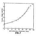
- Example 1 Bellows as resilient means.
- Figure 1 illustrates an embodiment of the invention employing bellows 6 as a resilient means.
- Fluorescent composition 8 is attached to surface 4 of the bellows.
- Fiber optic 2 illuminates fluorescent composition 8 and collects the resulting fluorescent emissions.
- Collar 12 allows bellows 6 to be attached to fiber optic 2 and includes vent 14 so that bellows compression is determined solely by the ambient pressure and the effective spring constant of the bellows. Vent 14 is not critical to the invention.
- the choice of a particular bellows is dictated by several factors, such as the operating temperature range, the nature of the pressurized fluid with which the bellows will be in contact, the operating pressure range, the expected frequency of pressure fluctuations, and so on.
- a commercially available stainless steel bellows (Servometer Corp., Cedar Grove, NJ) was employed in one embodiment.
- the diameter of the bellows, dimension 10 in Figure 1 was 1/4 inch (0.64 cm).
- the stainless steel bellows 6 was silver-soldered onto metal collar 12, which included vent 14.
- Fluorescent composition 8 comprised filter paper soaked in fluoroscein.
- Fiber optic 2 was a 200 meter, 200-micron diameter Valtec PC-10 (Valtec Optical Group, waltham, MA).
- the light source was an argon laser operating at 488 nm and 10 mw, and the photoelectric means was a Spex double monochrometer (Spex Corp., Metuchen, NJ).
- Figure 7 illustrates the relative signal intensity as a function of differential pressure for this embodiment.
- Another embodiment especially amenable to miniaturization employs a resilient means which comprises plastic bubble 40 with interior 42 (in Figure 4) attached to the second end 44 of fiber optic 46, that is, the distal end of fiber optic 46 relative to the detection means and the light source.
- a fluorescent composition can either be mixed with the plastic material forming bubble 40 or the fluorescent composition can be attached as a coating, as illustrated by 48 in Figure 4.
- Bubble 40 of this embodiment of the pressure-sensitive optrode can be formed in at least two ways. First, a mixture is formed which comprises a plastic dissolved in a volatile solvent. Second, a small Quantity of the mixture is placed on the second end of the fiber optic. And third, an illumination beam is directed into the first end of the fiber optic at an elevated power level, so that the attached droplet of mixture begins to heat and a bubble 40 forms.
- a second method of constructing this embodiment incluoes steps of dissolving a plastic in a vessel containing a volatile solvent, agitating the resulting solution until small spheroidal, bubbles form at the surface of the liquid, attaching one of the preformed bubbles to the second end of the fiber optic, and allowing the volatile solvent to evaporate, leaving the plastic bubble 44 attached to second end 40 of fiber optic 46.
- a fluorescent composition may be applied to the outside of the bubble or blended with plastic/solvent mixture prior to forming the bubbles.
- Example 3 Fluid Column in a Tube as Resilient Means
- Figure 5 is a cross section of an embodiment employing a fluid column in a tube as the resilient means.
- Fiber optic 60 with cladding 62, core 64, ano protective sheath 66, is fixedly attached to a first end 90 of tube 68.
- Fixing means 70 for attaching fiber optic 60 to tube 68 can be an adhesive, for example an epoxy, cyanoacrylate, or cellulose adhesive.
- tube 68 preferably comprises a catheter-sized tube, i.e., a tube amenable to insertion into the lumen of a vein or artery, made of material resistant to corrosion by physiological fluids, for example glass, plastic, stainless steel, nickel or nickel alloys. More preferably tube 68 comprises a catheter-sized tube less than a millimeter in diameter. It is important that fixing means 70 form an air-tight seal between the end of fiber optic 60 and tube 68. An air space, or bubble of trapped gas, 80 surrounding the second end of the fiber optic is compressd when increasing pressure drives a column of fluid 72, having a first surface 74 and a second surface 76, toward fiber optic 60.
- the range of movement of column through the bore of tube 68 should substantially include the region defineo by the cone (shown in cross section in Figure 5 by lines 78 and 78') adjacent to its apex, i.e., the region of maximal sensitivity described above.
- the fluid column 72 comprises a fluorescent material mixed with any fluid which is sufficiently viscous to remain in the bore of tube 68 and which is Immiscible with the fluid whose pressure is to be determined.
- the fluid containing the fluorescent material is referred to as the carrier fluid.
- hydrophobic fluids are preferred as the carrier fluid, e.g. fats or waxes. Fats are especially preferred because they are non-toxic, they can be mixed to obtain a wide range of melting points, ano there are many fat soluble fluorescent materials. Fats with melting points above room temperature and below body temperature are most preferred for invasive blood pressure measurements. Such melting points allow the optrode to be handled and transported with the fat in solid form, which lessens the chances of contamination or loss of the fluid column 72.
- olein, palmitin, and stearin can be mixed in various proportions to obtain melting points between roon. temperature and body temperature.
- olein, palmitin, and stearin can be mixed in various proportions to obtain melting points between roon. temperature and body temperature.
- Fat soluble fluorescent molecules are preferred and, when structural formulas are available, can be selected according to oroinary solubility rules for organic molecules, e.g., S h ugar, et al., Chemical 'lechnicians' Ready Reference Handbook, Second Edition (McGraw-Hill Book Co., San Francisco, 1981). Further selection can be made empirically.
- p-Oligophenylenes such as p-quaterphenyl
- oxazole and oxadiazole derivatives such as 2,5-diphenyloxazole (the common scintillator solute PPO)
- other ring systems e.g. benzene, naphthalene, pyridine, pyrrole,or indole.
- fat soluble fluorescent molecules suitable for use in the present embodiment include, but are not limited to, methyl eosin, rhodamine 66, rhoaamine 36, phosphine, tetracycline, chromoxane brilliant red BL, chlorophyll, alizarin rubinol, evans blue, procion yellow, cryptocyanine, pyrene, rubrene, N-p h enylnaphthylamine, victoria blue B, 7-ethoxyresorufin, 2-hydroxystilbamidine, parinaric acid, sempervirene, 1,6-diphenylhexatriene, P-puaterphenyl, tetraphenylbuta
- Non-hazardous fat soluble fluorescent molecules are preferred for medical uses. whether a particular fat soluble fluorescent molecule can be used in a non-hazardous manner oepends on several considerations: (1) concentration of the fluorescent molecules necessary to generate measurable signals, (2) blood concentrations and durations of such concentrations that can cause toxic or genotoxic effects, and (3) the rate at which the fluorescent molecules leaks into the blood stream during operation.
- the fluorescent material comprises fluorescent particles dispersed in the carrier fluid, e.g., powders, microspheres, or microencapsulated fluorescent dyes.
- Fluorescent micros- p h eres are the most preferred fluorescent material. Fluorescent microspheres suitable for use with the present embodiment are available commercially either in forms maae from fluorescent compositions or in forms which can be rendered fluorescent by covalently attaching fluoresecent molecules (e.g., Polyscience, Inc.
- fluorescent microspheres are less likely to diffuse out of the carrier fluid than fluorescent molecules. Consequently, such fluorescent materials are safer, and the choice of applicable fluorescent molecules can be increased by covalently bonding otherwise unacceptably mobile or toxic molecules to microspheres.
- the optrode must either be constructed from materials which do not induce blood coagulation (or more precisely, thrombogenesis) or be treated with agents which prevent blood coagulation.
- Such materials and treatments are well known in the art.
- Lemm, et a1., Medical and Biological Engineering and Computation, Vol. 16, pp. 521-526 (1980); and Francis, U.S. Patent 4,387,183 provide lists of commercially available t h romboresistant materials. (or materials that can be renaered thromboresistant). Joh, U.S. Patent 4,329,383; Hammar, U.S. Patent 4,326,532; and Joh, U.S.
- Patent 4,415,490 contain reviews of methods for rendering materials thromboresistant. Maugh, Science, Vol. 217, pp. 1129-1130 (1982) discusses the use of albumin coatings for reducing thrombogencicity. The preferred method of treatment is heparinization. The Joh and Hammar patents cited above deal primarily with methods of heparinization. Heparinization can be accomplished in several ways.
- heparin coatings are available, such as Glassclad HP (a tradenamed product from Petrarch Systems Bristol, PA) for heparinizing glass surfaces and TDKAC (tri-dode cy'methyl-ammonium chloride) - heparin (available from Po'ysciences, Inc., Warrington, PA).
- TDMAC-heparin a fluorescent fluid comprising a fat or fats possesses thrombogenic activity
- TUMAC-heparin tri-dode cy'methyl-ammonium chloride
- Example 4 Manufacture of Resilient Means Comprising a Fluid Column in a Tube
- the first step in the preferred method of manufacturing the optrode employing a fluid column in a tube as resilient means is coaxially positioning and fixedly attaching the second end of the fiber optic 60 to the first end 90 of tube 68 of predetermined inside diameter, indicated by dimension "e” in Figure 5.
- protective sheatn 66 of the secono end of fiber optic 60 is removed over a distance from the end face, indicated by dimension "d” in Figure 4. Removing the protective sheath creates a larger bubble volume 80 which, in turn, allows the column of fluid 72 a greater range of travel for a given variation in pressure.
- the range of travel of the column of fluid 72 depends on bubble volume 80 and inside diameter of tube 68. The best values for these parameters for a given application are determined empirically.
- the preferred range of travel for operation depends on the numerical aperture of the fiber optic, as discussed above.
- the step of inserting and attaching includes inserting the fiber optic such that the distance, indicated by the letter "c", is known.
- the second step is placing the second end 92 of tube 68 in contact with a reservoir 100 ( Figure 6A) of fluid under conditions wherein the surrounding gas 102 is at a first predetermined pressure, preferably below atmospheric pressure.
- the third step is increasing the pressure of the surrounding gas 102' in Figure 6B to a second predetermined pressure (preferably still below atmospheric pressure) while second end 92 of the tube is still in contact with reservoir 100 of fluorescent fluid 100 so that a column 101 of the fluid is forced into the tube.
- the fourth step is removing the second end of the tube from the reservoir of fluid.
- the fifth step is increasing the pressure of the surrounding gas 102" ( Figure 6C), preferably to atmospheric pressure, so that fluid column 101 is drawn back from the second end of the tube by a predetermined distance indicated by letter "a" in Figure 5.
- Appropriate choices of the first and second predetermined pressures determines how close first surface 74 of the column of fluid 72 is to the end face of fiber optic 60, and how far second face 76 of the column of fluid 72 is recesseo from the second end of the tube, i.e., the distance indicated by the letter "a" in Figure 5.
- the temperature is maintained at a level so that the fluid column is in liquid form during the above-describeo second through fifth steps.
- the first and second predetermined pressures are determined by straight forward application of the ideal gas law.
- a step or steps of treating with thromboresistant agents must be made, if necessary.
- the second end of the fiber optic and the tube are treated with a thromboresistant agent.
- this step comprises heparinizing. If the fluid contains thrombogenic agents an additional step of heparinizing must be made.
- the additional step of heparinizing comprises treating second surface 76 of the column of fluid 72 with TDMAC-heparin.
- Figure 8 illustrates the performance of an example of an embodiment of the invention.
- Curve A of Figure 8 is a reference pressure signal repeatedly generated by a Model 601A Blood Pressure Systems Calibrator (BioTek Instruments, Inc., Burlington VT).
- Curve B of Figure 8 is the intensity of the optical signal generated by the particular embodiment in response to the reference pressure. Minor discrepancies between the curves exist because no signal processing means for linearizing the optrode's response signal were included in the detection means of the particular embodiment.
- the preferred embodiment includes such signal processing means.
- the particular embodiment corprised a fiber optic (140 pm cladding diameter, 100 ⁇ m core diameter, e.g., model S-140 from General Fiber Optics, Caldwell, NJ) coaxially inserted approximately 300 pm into a glass capillary tube (300 pm inside diameter and 0.53 cm in length) and glued in place with an epoxy adhesive.
- the fluorescent fluid comprised water with 300 ppm fluoroscein. The fluorescent fluid was loaded into the capillary tube so that first surface 74 of the column extended 500 pm into the tube from second end of the tube.
- Ruby affords a means of constructing a dual pressure-and-temperature-sensitive optrode within the purview of the subject invention.
- Ruby fluoresces at two closely spaced wavelengths, designated the R 1 and R 2 lines.
- the relative intensity of the two lines is a function of ambient temperature. Total signal intensity depends on both pressure and temperature. However, by measuring the relative intensity of the R 1 and R 2 emissions, not only can the temperature be determined, but also the temperature-dependent contribution to the total fluorescent intensity can be factored out to give an accurate pressure reading.
- Tnis embodiment requires a special detection means for analyzing the fluorescent signal generated by the optrode.
- the detection means has a stored table of ordered pairs relating the values of the R 1 /R 2 -intensity ratios to ruby temperatures. This table is referred to as the "stored temperature-ratio table.
- the detection means has the capability of separately measuring the intensity of the R 1 emission line, collected and separated from the illumination beam, the intensity of the R 2 emission line, collected and separated from the illumination beam, and the intensity of the total fluorescence collected and separated from the illumination beam.
- the detection means has a stored table of ordered pairs relating total ruby fluorescence to ruby temperature under the condition that the ruby is at a predetermined distance from the second end of the fiber optic. This table is referred to as the "stored temperature-intensity table.” A value of total ruby fluorescence can be read from the stored temperature-intensity table, once the ruby temperature is obtained from the stored temperature-ratio table.
- the detection means has a table of ordered pairs that relates differences between actual total fluorescences and total ruby fluorescences from the stored temperature-intensity table to pressures. This table is referred to as the "stored pressure-intensity difference table.” A value for pressure is read from the stored pressure-intensity difference table, once the computed difference is obtained.
- a data acquisition computer such as a DEC LSI-11 (Digital Equipment Corp., waltham, MA).
- ruby Another advantage of ruby is that the range of preferential wavelengths for fluorescent excitation includes the output wavelengtn of helium-neon lasers. Therefore, these inexpensive and readily available lasers can be used as light sources for pressure optrodes employing ruby as their fluorescent compositions.
- the subject invention can be adapted to measuring changes in salt concentrations by sensing changes in osmotic pressure across a'predetermlned semi-permeable membrane.
- Such an adaptation requires that the resilient means of the pressure-sensitive optrode be enclosed by a hollow body with at least one port.
- the predetermined semi-permeable membrane covers the port so that only water or selected ions can enter the hollow body.
- the hollow body could be a hollow cylinder surrounding the resilient means attached to the second end of the fiber optic by one end and open at the other end.
- the port is the open end of the cylinder.
- the concentration of a known salt can be monitored by choosing a semi-permeable membrane impermeable to the known salt, but permeable to the surrounding solvent.
- a quantity of the known salt is placed inside the hollow body so that the concentration inside the hollow body is the same as the concentration outside the hollow body. Under these conditions, no osmotic pressure is generated inside the hollow body; therefore, no change occurs in the optical signal generated by the optrode. If the exterior salt concentration changes, however, osmotic pressure arises inside the hollow body, causing the resilient means to move closer to or farther away from the second end of the fiber optic, depending on whether the outside concentration change is an increase or decrease. In either case, the optical signal generated by the optrode makes a corresponding change.
Landscapes
- Physics & Mathematics (AREA)
- General Physics & Mathematics (AREA)
- Health & Medical Sciences (AREA)
- Life Sciences & Earth Sciences (AREA)
- Cardiology (AREA)
- Electromagnetism (AREA)
- Medical Informatics (AREA)
- Animal Behavior & Ethology (AREA)
- Pathology (AREA)
- Engineering & Computer Science (AREA)
- Biomedical Technology (AREA)
- Heart & Thoracic Surgery (AREA)
- Physiology (AREA)
- Molecular Biology (AREA)
- Surgery (AREA)
- Biophysics (AREA)
- General Health & Medical Sciences (AREA)
- Public Health (AREA)
- Veterinary Medicine (AREA)
- Vascular Medicine (AREA)
- Measuring Fluid Pressure (AREA)
- Investigating, Analyzing Materials By Fluorescence Or Luminescence (AREA)
- Light Guides In General And Applications Therefor (AREA)
- Measuring Pulse, Heart Rate, Blood Pressure Or Blood Flow (AREA)
Applications Claiming Priority (2)
| Application Number | Priority Date | Filing Date | Title |
|---|---|---|---|
| US675633 | 1984-11-28 | ||
| US06/675,633 US4599901A (en) | 1982-09-30 | 1984-11-28 | Pressure-sensitive optrode |
Publications (2)
| Publication Number | Publication Date |
|---|---|
| EP0183329A2 true EP0183329A2 (de) | 1986-06-04 |
| EP0183329A3 EP0183329A3 (de) | 1989-07-26 |
Family
ID=24711339
Family Applications (1)
| Application Number | Title | Priority Date | Filing Date |
|---|---|---|---|
| EP85300472A Withdrawn EP0183329A3 (de) | 1984-11-28 | 1985-01-24 | Druckempfindliche Optrode |
Country Status (3)
| Country | Link |
|---|---|
| US (1) | US4599901A (de) |
| EP (1) | EP0183329A3 (de) |
| JP (1) | JPS61128941A (de) |
Cited By (1)
| Publication number | Priority date | Publication date | Assignee | Title |
|---|---|---|---|---|
| CN111928982A (zh) * | 2020-07-27 | 2020-11-13 | 山东光安智能科技有限公司 | 一种矿用可视化光纤光栅大量程锚杆索应力监测传感器 |
Families Citing this family (22)
| Publication number | Priority date | Publication date | Assignee | Title |
|---|---|---|---|---|
| US4768886A (en) * | 1984-12-26 | 1988-09-06 | The Regents Of The University Of California | Method and apparatus for simultaneously measuring temperature and pressure |
| US4883354A (en) * | 1985-10-25 | 1989-11-28 | Luxtron Corporation | Fiberoptic sensing of temperature and/or other physical parameters |
| US4752141A (en) * | 1985-10-25 | 1988-06-21 | Luxtron Corporation | Fiberoptic sensing of temperature and/or other physical parameters |
| EP0312293A3 (de) * | 1987-10-16 | 1990-03-14 | O.C.T. Optical Chemical Technologies Limited | Fühlervorrichtung für die Analyse |
| US4856317A (en) * | 1988-05-02 | 1989-08-15 | Fiberoptic Sensor Technologies, Inc. | Vacuum calibration system and method for fiberoptic pressure transducer |
| US4892383A (en) * | 1989-02-17 | 1990-01-09 | Fiberchem Inc. | Reservoir fiber optic chemical sensors |
| US5343861A (en) * | 1989-04-10 | 1994-09-06 | Herman Wesley K | Disposable tonometer cover with fluorescein dye |
| US4986671A (en) * | 1989-04-12 | 1991-01-22 | Luxtron Corporation | Three-parameter optical fiber sensor and system |
| US5061846A (en) * | 1989-05-11 | 1991-10-29 | Conoco Inc. | Detecting disturbance using optical gap sensing |
| US5313957A (en) * | 1990-01-05 | 1994-05-24 | Medamicus, Inc. | Guide wire mounted pressure transducer |
| US5124130A (en) * | 1990-05-22 | 1992-06-23 | Optex Biomedical, Inc. | Optical probe |
| US5318029A (en) * | 1992-02-11 | 1994-06-07 | Oasis Medical, Inc. | Tonometer shield |
| DK48092D0 (da) * | 1992-04-10 | 1992-04-10 | Novo Nordisk As | Apparat |
| US5279793A (en) * | 1992-09-01 | 1994-01-18 | Glass Alexander J | Optical osmometer for chemical detection |
| US5485741A (en) * | 1993-10-19 | 1996-01-23 | Medamicus, Inc. | Vacuum calibration method for an optical fiber pressure transducer |
| CA2198853A1 (en) * | 1994-09-02 | 1996-03-14 | Biometric Imaging, Inc. | Calibration method and apparatus for optical scanner |
| GB9526588D0 (en) * | 1995-12-28 | 1996-02-28 | British Aerospace | Pressure measuring device |
| US6756579B2 (en) * | 2002-03-27 | 2004-06-29 | The United States Of America As Represented By The Secretary Of The Navy | Optical fiber based apparatus and sensor with enhanced signal for pressure measurements |
| US7430357B2 (en) * | 2003-06-27 | 2008-09-30 | General Dynamics Advanced Information Systems, Inc. | Hermetic seal on metallized fiber optics |
| US6945117B2 (en) * | 2003-08-29 | 2005-09-20 | Dana Corporation | Gasket having a fiber-optic pressure sensor assembly |
| CN114046960B (zh) * | 2022-01-12 | 2022-03-25 | 中国空气动力研究与发展中心空天技术研究所 | 基于预先动态标定的气动探针定常流场连续测试方法 |
| CN121185506B (zh) * | 2025-11-24 | 2026-02-17 | 南开大学 | 一种光纤传感单元、光纤荧光压力传感器及制备方法 |
Family Cites Families (14)
| Publication number | Priority date | Publication date | Assignee | Title |
|---|---|---|---|---|
| DE2450080A1 (de) * | 1974-10-22 | 1976-04-29 | Licentia Gmbh | Verfahren und einrichtung zur druckmessung |
| US4075493A (en) * | 1976-12-16 | 1978-02-21 | Ronald Alves | Optical temperature measurement technique utilizing phosphors |
| US4200110A (en) * | 1977-11-28 | 1980-04-29 | United States Of America | Fiber optic pH probe |
| US4215275A (en) * | 1977-12-07 | 1980-07-29 | Luxtron Corporation | Optical temperature measurement technique utilizing phosphors |
| US4158310A (en) * | 1978-01-30 | 1979-06-19 | University Of Southern California | Optical pressure transducer of randomly distributed fiber optics |
| US4344438A (en) * | 1978-08-02 | 1982-08-17 | The United States Of America As Represented By The Department Of Health, Education And Welfare | Optical sensor of plasma constituents |
| SE413555B (sv) * | 1978-09-15 | 1980-06-02 | Asea Ab | Fiberoptiskt metdon |
| US4245507A (en) * | 1979-09-10 | 1981-01-20 | Samulski Thaddeus V | Temperature probe |
| GB2103786A (en) * | 1981-08-14 | 1983-02-23 | Ici Plc | Fibre optic sensor |
| EP0074055A3 (de) * | 1981-09-03 | 1984-09-12 | Honeywell Inc. | Druckfühler mit Fiber-Lichtleiter |
| US4447546A (en) * | 1982-08-23 | 1984-05-08 | Myron J. Block | Fluorescent immunoassay employing optical fiber in capillary tube |
| US4492121A (en) * | 1982-09-30 | 1985-01-08 | The United States Of America As Represented By The Secretary Of The Navy | Gauge for measuring high transient pressures |
| US4509370A (en) * | 1982-09-30 | 1985-04-09 | Regents Of The University Of California | Pressure-sensitive optrode |
| ATE58790T1 (de) * | 1983-05-25 | 1990-12-15 | Camino Lab Inc | Fiberoptischer messwandler. |
-
1984
- 1984-11-28 US US06/675,633 patent/US4599901A/en not_active Expired - Fee Related
-
1985
- 1985-01-24 EP EP85300472A patent/EP0183329A3/de not_active Withdrawn
- 1985-01-25 JP JP60012317A patent/JPS61128941A/ja active Pending
Cited By (2)
| Publication number | Priority date | Publication date | Assignee | Title |
|---|---|---|---|---|
| CN111928982A (zh) * | 2020-07-27 | 2020-11-13 | 山东光安智能科技有限公司 | 一种矿用可视化光纤光栅大量程锚杆索应力监测传感器 |
| CN111928982B (zh) * | 2020-07-27 | 2021-09-10 | 山东光安智能科技有限公司 | 一种矿用可视化光纤光栅大量程锚杆索应力监测传感器 |
Also Published As
| Publication number | Publication date |
|---|---|
| JPS61128941A (ja) | 1986-06-17 |
| US4599901A (en) | 1986-07-15 |
| EP0183329A3 (de) | 1989-07-26 |
Similar Documents
| Publication | Publication Date | Title |
|---|---|---|
| US4599901A (en) | Pressure-sensitive optrode | |
| US4784811A (en) | Method of constructing improved pressure-sensitive optrode | |
| US4509370A (en) | Pressure-sensitive optrode | |
| JP2597634B2 (ja) | 光フアイバー活性化学的変換器 | |
| US5142155A (en) | Catheter tip fluorescence-quenching fiber optic pressure sensor | |
| US5039492A (en) | Optical pH and gas concentration sensor | |
| US4752115A (en) | Optical sensor for monitoring the partial pressure of oxygen | |
| US4577109A (en) | Remote multi-position information gathering system and method | |
| US4803049A (en) | pH-sensitive optrode | |
| US4785814A (en) | Optical probe for measuring pH and oxygen in blood and employing a composite membrane | |
| EP0250151B1 (de) | Optisches Mehrkanalübertragungssystem | |
| US4833091A (en) | Sensor system | |
| US4842783A (en) | Method of producing fiber optic chemical sensors incorporating photocrosslinked polymer gels | |
| US5119463A (en) | Compound optical probe employing single optical waveguide | |
| CA1292665C (en) | Fiber optic probe for quantification of colorimetric reactions | |
| EP0457292A2 (de) | Fiberoptisches Bündel mit verbesserter Konfiguration zur Blutgasmessung und Verfahren zur Herstellung | |
| US5093266A (en) | Sensor system | |
| AU614649B2 (en) | Optical fiber distribution system for an optical fiber sensor | |
| EP0341305B1 (de) | Modularer chemischer sensor aus optischen fasern | |
| EP0477501A2 (de) | Vorrichtung zur kontinuierlichen Überwachung einer Mehrzahl von chemischen Analyten mittels einer einzigen optischen Faser und Herstellungsverfahren | |
| EP0253492B1 (de) | Faseroptische Sonde | |
| US4854321A (en) | Integrated optic system for monitoring blood gases | |
| GB2371360A (en) | Multiple parameter fiber optic probe | |
| JPS6354146A (ja) | 圧力モニタ装置 | |
| JPH01107737A (ja) | 生理学的測定装置のための光ファイバープローブコネクター |
Legal Events
| Date | Code | Title | Description |
|---|---|---|---|
| PUAI | Public reference made under article 153(3) epc to a published international application that has entered the european phase |
Free format text: ORIGINAL CODE: 0009012 |
|
| AK | Designated contracting states |
Kind code of ref document: A2 Designated state(s): AT BE CH DE FR GB IT LI LU NL SE |
|
| PUAL | Search report despatched |
Free format text: ORIGINAL CODE: 0009013 |
|
| AK | Designated contracting states |
Kind code of ref document: A3 Designated state(s): AT BE CH DE FR GB IT LI LU NL SE |
|
| 17P | Request for examination filed |
Effective date: 19900126 |
|
| 17Q | First examination report despatched |
Effective date: 19900920 |
|
| STAA | Information on the status of an ep patent application or granted ep patent |
Free format text: STATUS: THE APPLICATION IS DEEMED TO BE WITHDRAWN |
|
| 18D | Application deemed to be withdrawn |
Effective date: 19910131 |
|
| RIN1 | Information on inventor provided before grant (corrected) |
Inventor name: HIRSCHFELD, THOMAS B. |