EP0183343B1 - Heizvorrichtung für Brennstofftank - Google Patents
Heizvorrichtung für Brennstofftank Download PDFInfo
- Publication number
- EP0183343B1 EP0183343B1 EP85306067A EP85306067A EP0183343B1 EP 0183343 B1 EP0183343 B1 EP 0183343B1 EP 85306067 A EP85306067 A EP 85306067A EP 85306067 A EP85306067 A EP 85306067A EP 0183343 B1 EP0183343 B1 EP 0183343B1
- Authority
- EP
- European Patent Office
- Prior art keywords
- fuel
- tank
- heating
- supply system
- processor
- Prior art date
- Legal status (The legal status is an assumption and is not a legal conclusion. Google has not performed a legal analysis and makes no representation as to the accuracy of the status listed.)
- Expired
Links
- 238000010438 heat treatment Methods 0.000 title claims abstract description 46
- 239000002828 fuel tank Substances 0.000 title claims abstract description 40
- 239000000446 fuel Substances 0.000 claims abstract description 226
- 238000012545 processing Methods 0.000 claims abstract description 27
- 239000002826 coolant Substances 0.000 claims abstract description 9
- 238000002485 combustion reaction Methods 0.000 claims abstract description 7
- 239000012530 fluid Substances 0.000 claims description 19
- 229910052751 metal Inorganic materials 0.000 claims description 4
- 239000002184 metal Substances 0.000 claims description 4
- 239000000295 fuel oil Substances 0.000 abstract description 14
- 239000004020 conductor Substances 0.000 abstract description 2
- 230000009969 flowable effect Effects 0.000 abstract description 2
- 238000010792 warming Methods 0.000 description 9
- 238000007654 immersion Methods 0.000 description 5
- 238000012546 transfer Methods 0.000 description 4
- 238000013459 approach Methods 0.000 description 3
- 230000008901 benefit Effects 0.000 description 3
- 239000002245 particle Substances 0.000 description 3
- XLYOFNOQVPJJNP-UHFFFAOYSA-N water Substances O XLYOFNOQVPJJNP-UHFFFAOYSA-N 0.000 description 3
- 239000001993 wax Substances 0.000 description 3
- 230000005540 biological transmission Effects 0.000 description 2
- 238000004891 communication Methods 0.000 description 2
- 239000007789 gas Substances 0.000 description 2
- 239000000463 material Substances 0.000 description 2
- 239000012188 paraffin wax Substances 0.000 description 2
- 239000007787 solid Substances 0.000 description 2
- RYGMFSIKBFXOCR-UHFFFAOYSA-N Copper Chemical compound [Cu] RYGMFSIKBFXOCR-UHFFFAOYSA-N 0.000 description 1
- 229910052782 aluminium Inorganic materials 0.000 description 1
- XAGFODPZIPBFFR-UHFFFAOYSA-N aluminium Chemical compound [Al] XAGFODPZIPBFFR-UHFFFAOYSA-N 0.000 description 1
- 230000015572 biosynthetic process Effects 0.000 description 1
- 229910052802 copper Inorganic materials 0.000 description 1
- 239000010949 copper Substances 0.000 description 1
- 239000013078 crystal Substances 0.000 description 1
- 230000001419 dependent effect Effects 0.000 description 1
- 230000000994 depressogenic effect Effects 0.000 description 1
- 230000000694 effects Effects 0.000 description 1
- 230000007613 environmental effect Effects 0.000 description 1
- 230000001747 exhibiting effect Effects 0.000 description 1
- 238000001914 filtration Methods 0.000 description 1
- 239000012535 impurity Substances 0.000 description 1
- 238000011068 loading method Methods 0.000 description 1
- 239000010687 lubricating oil Substances 0.000 description 1
- 238000000034 method Methods 0.000 description 1
- 239000003921 oil Substances 0.000 description 1
- 238000013021 overheating Methods 0.000 description 1
- 230000000737 periodic effect Effects 0.000 description 1
- 230000000750 progressive effect Effects 0.000 description 1
- 230000000135 prohibitive effect Effects 0.000 description 1
- 230000002035 prolonged effect Effects 0.000 description 1
- 238000000926 separation method Methods 0.000 description 1
- 238000002791 soaking Methods 0.000 description 1
- 238000007711 solidification Methods 0.000 description 1
- 230000008023 solidification Effects 0.000 description 1
- 239000006163 transport media Substances 0.000 description 1
Images

Classifications
-
- F—MECHANICAL ENGINEERING; LIGHTING; HEATING; WEAPONS; BLASTING
- F02—COMBUSTION ENGINES; HOT-GAS OR COMBUSTION-PRODUCT ENGINE PLANTS
- F02M—SUPPLYING COMBUSTION ENGINES IN GENERAL WITH COMBUSTIBLE MIXTURES OR CONSTITUENTS THEREOF
- F02M31/00—Apparatus for thermally treating combustion-air, fuel, or fuel-air mixture
- F02M31/02—Apparatus for thermally treating combustion-air, fuel, or fuel-air mixture for heating
- F02M31/16—Other apparatus for heating fuel
-
- F—MECHANICAL ENGINEERING; LIGHTING; HEATING; WEAPONS; BLASTING
- F23—COMBUSTION APPARATUS; COMBUSTION PROCESSES
- F23K—FEEDING FUEL TO COMBUSTION APPARATUS
- F23K5/00—Feeding or distributing other fuel to combustion apparatus
- F23K5/02—Liquid fuel
- F23K5/14—Details thereof
- F23K5/20—Preheating devices
-
- F—MECHANICAL ENGINEERING; LIGHTING; HEATING; WEAPONS; BLASTING
- F02—COMBUSTION ENGINES; HOT-GAS OR COMBUSTION-PRODUCT ENGINE PLANTS
- F02B—INTERNAL-COMBUSTION PISTON ENGINES; COMBUSTION ENGINES IN GENERAL
- F02B3/00—Engines characterised by air compression and subsequent fuel addition
- F02B3/06—Engines characterised by air compression and subsequent fuel addition with compression ignition
-
- Y—GENERAL TAGGING OF NEW TECHNOLOGICAL DEVELOPMENTS; GENERAL TAGGING OF CROSS-SECTIONAL TECHNOLOGIES SPANNING OVER SEVERAL SECTIONS OF THE IPC; TECHNICAL SUBJECTS COVERED BY FORMER USPC CROSS-REFERENCE ART COLLECTIONS [XRACs] AND DIGESTS
- Y02—TECHNOLOGIES OR APPLICATIONS FOR MITIGATION OR ADAPTATION AGAINST CLIMATE CHANGE
- Y02T—CLIMATE CHANGE MITIGATION TECHNOLOGIES RELATED TO TRANSPORTATION
- Y02T10/00—Road transport of goods or passengers
- Y02T10/10—Internal combustion engine [ICE] based vehicles
- Y02T10/12—Improving ICE efficiencies
Definitions
- This invention relates to a fuel heating system and particularly, to a system for heating fuel oil within a fuel tank before it is conducted into a fuel delivery circuit.
- Diesel engine powered machines such as motor vehicles, stationary generating plants, and other fuel oil combustion devices are often operated in environmental conditions wherein the fuel oil and fuel delivery circuit are subjected to cold ambient temperatures.
- fuel oils become viscous, and develop paraffin or wax particles.
- These fuels have characteristic temperatures at which they become “cloudy” due to the pressure of dispensed wax crystals and at which they "freeze” or become a semi-solid mass, referred to as their cloud and pour points, respectively.
- Some diesel engine fuels have a cloud point of -7°C (20°F) and a pour point of -18°C (0°F). Additionally, water which invariably is mixed with the fuel oil can freeze, forming ice particles.
- DE-A-3 241 065 discloses a fuel supply system in accordance with the prior art portion of claim 1 in that a single heating means is provided using engine coolant to supply heat back to the main fuel tank and to a smaller quantity of fuel during passage from the fuel tank to the engine.
- the present invention as characterised in claim 1, provides an additional local electrical heater for the relatively small quantity of fuel waiting in the small fuel processor prior to being supplied to the engine. This assists in rapidly raising the fuel to a temperature at which it is usable and is not dependent upon the engine being operative as the source of heat.
- the above objects of this invention are achieved by employing a fuel processor device which acts as a small-capacity fuel reservoir which provides warmed fuel for initial operation, and a larger capacity main fuel reservoir which holds the bulk of the stored fuel.
- the larger capacity main fuel reservoir includes heating means associated with the fuel processor to provide a sufficient flow rate of warmed fuel to sustain continued operation of the associated fuel oil fired device.
- High overall thermal efficiency is provided by heating a very small quantity of fuel oil for initial start-up and by providing a steady state energy input level into the main fuel reservoir which warms fuel to provide a flow rate of warmed fuel related to the fuel consumption rate of the fuel consuming device. No attempt need be made in accordance with this invention to maintain the entire contents of the main fuel reservoir in a wax-free state, even while the fuel consuming device is operating.
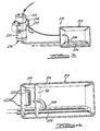
- a fuel heating system is shown in Figure 1 and is generally designated there by reference character 10.
- System 10 is particularly adapted for use in a fuel supply system for a diesel engine powered device such as a motor vehicle or a power generating plant.
- System 10 and those described hereinafter, however, may be used in conjunction with any type of fuel combustion operated device, including turbine engines, furnaces, etc.
- Fuel heating system 10 includes fuel tank 12 which is divided into two sections, fuel processing section 14 and main fuel reservoir section 16, which are physically separated by wall 18.
- Fuel processing section 14 includes internally disposed conduit 20 which conducts a heated fluid such as engine coolant within fuel processing section 14 and is in heat exchange relationship with the fuel therein, thereby warming the fuel.
- fuel processing section 14 includes electric immersion heater 22 which may be employed to maintain the temperature of the fuel within the fuel processor section 14 at a level above its cloud point, thereby maintaining the associated device in a state of constant readiness. Electric immersion heater 22 may also be energized a short time period before attempted start-up of the associated fuel oil fired apparatus, thereby warming a small quantity of fuel for initial operation.
- Wall 18 may be formed from any suitable material, for example, sheet metal, and acts to separate the fluids within fuel tank 12 into two sections.
- Fuel outlet conduit 38, disposed in fuel processing section 14, serves to conduct fuel to the remaining branches of the fuel delivery circuit or to a particulate filter mounted within or to fuel tank 10.
- Drain valve 36 is optionally provided to permit the periodic removal of water or other impurities which collect in the lower portion of section 14.
- conduit 20 is elongated to have a portion thereof, identified by reference number 26, which extends into a lower portion of main fuel reservoir section 16.
- Conduit portion 26 preferably is shaped to provide an optimum or adequate heat transfer surface and is positioned immediately above a portion of the floor of tank 12.
- Engine coolant or another heated fluid such as oil, exhaust gases, etc. is preferably conducted within conduit 20 such that it is first conducted into section 14 and thereafter into section 16. This direction of flow insures that the greatest amount of heat available for fuel warming is provided in fuel processor section 14.
- Fuel pickup tube 24 forms a fuel communication path between sections 14 and 16.
- Fuel pickup tube 24 has an inlet which is located in close proximity with conduit 26 within fuel storage section 16 and is preferably positioned between the legs of conduit 26. Further, fuel pickup tube 24 is preferably located slightly above conduit 26. This relationship of fuel pickup tube 24 with respect to conduit 26 provides a location desirable from a heat trasnfer view point to provide warmed fuel to fuel processing section 14.
- conduit 26 and fuel pickup tube 28 may be located in a locally depressed sump section of the tank.
- the tank shapes shown herein are provided for illustrative purposes only.
- the electric heater 22 is employed, to provide a quantity of warmed fuel required to support internal combustion. Thereafter, when a warmed fluid becomes available for transmission within conduits 20 and 26, the fuel becomes warmed in a progressive manner, to above its pour point in main fuel reservoir section 16 to a more elevated temperature (preferably above the fuel's cloud point) in fuel processing section 14.
- Fuel heating system 110 like the first embodiment, includes fuel tank 112, divided into two sections; fuel processing section 114 and main fuel reservoir section 116.
- This embodiment varies from the first, however, in that wall 118 forms a fully enclosed vessel which is surrounded by fuel within section 116.
- a heat source comprising, for example, conduit 120 which conducts a heated fluid such as engine coolant within that section.
- Electrical immersion heater 122 is installed within fuel processing section 116 as an additional or exclusive heat source and may be continuously energized or energized a short period of time prior to engine start-up.
- This embodiment varies principally from the first in that conduit 120 is not extended to . form a section 26 within main fuel reservoir section 116.
- heat from section 114 is conducted into main fuel reservoir section 116 using heat radiating rods or tubes 128 which are attached to wall 118 in a manner permitting conductive heat transfer between these components.
- Rods 128 are preferably made from a metal exhibiting high heat conduction properties such as copper or aluminum. Heat is transferred through conduction to rods 128 and is thereafter dissipated to fuel surrounding the rods.
- fuel pickup tube 124 is employed which communicates fuel processing section 114 with fuel storage section 116.
- the orientation of pickup tube 124 is also like that previously described, i.e. it is placed in close proximity with the heat source and preferably vertically above it, thereby taking advantage of heat transfer principles to provide efficient preheating of fuel.
- a number of variations of the second embodiment of fuel heating system 110 are also well within the scope of this invention.
- a solid plate could be used in place of rods or tubes 128.
- so-called "heat pipes” could be used which are tubular members filled with a two- phase heat transport media. These devices exhibit exceptional heat transfer capabilities since they approach maintaining their entire surface at a uniform temperature despite localized thermal loadings.
- the use of heat radiating rods or pipes or other heat conduction means described in conjunction with this embodiment could also be employed with the planar shaped wall 18 of the first embodiment.
- a third embodiment of a fuel heating system according to this invention is shown with reference to Figure 3 and is designated there by reference character 210.
- This embodiment differs from the two previously described in that the fuel processing apparatus is physically separated from fuel tank 212.
- a separate fuel processor 230 is employed.
- This device may be any high-performance fuel processor which provides fuel heating such as that described by my issued U.S. Patent No. 4,368,716.
- Fuel processor 230 includes an internally disposed heated fluid conducting conduit 220, and fuel inlet and outlet 233 and 234, respectively.
- Fuel processor 230 also includes an auxiliary electric heater (not shown) and may further include a manually or automatically actuated drain valve 236.
- Another conduit 226 is disposed within fuel tank 212 in a fashion similar to that of the first embodiment.
- fuel pickup tube 224 is provided and oriented as previously described. Conduits are provided which communicate fuel pickup tube 224 with fuel processor 230 and conduit 220 with conduit 226. Otherwise, this device performs precisely like the first embodiment, in that a heated fluid, such as engine coolant, is conducted into the fuel processor 230 and thereafter into conduit 226 to provide localized warming of fuel in main fuel reservoir section 216.
- a heated fluid such as engine coolant
- FIG. 4 A fourth embodiment of a fuel heating system according to this invention is illustrated in Figure 4.
- This embodiment is similar to the first two in that fuel tank 212 is divided into two sections, fuel processing section 314 and main fuel reservoir section 316 by wall 318.
- conduit 20 is eliminated and section 314 is heated by electrical immersion heater 322.
- This heater may be constantly energized or energized a predetermined period of time before engine start-up. Once an engine is started, and particularly when it is used to power an electric generator, high levels of electrical power become available.
- a second immersion heater 338 is provided which extends into main fuel reservoir section 316. Therefore, after engine start-up, electrical power is provided to heater 338 to warm fuel in the vicinity of fuel pickup tube 324.
- heater 338 also acts to conduct heat within fuel processing section 314 provided by heater 322, even while the second heater 338 is not energized. This is accomplished by mounting a portion of heater 338 within section 314 and making the heater from a heat conducting material. Therefore, prior to energization of heater 338, fuel in the vicinity of fuel pickup tube 324 is heated to a point where it can be drawn into section 114 in a manner like that according to the second embodiment shown in Figure 2. The proximity of fuel pickup tube with heater 338 is substantially like that previously described for the previous embodiments. An automatic control system like that described previously is needed for the apparatus shown in Figure 4. Such control could be achieved by employing a separate temperature sensor or by employing a self limiting device for heaters 322 and 338 such as those made from positive temperature coefficient (PTC) materials.
- PTC positive temperature coefficient
Landscapes
- Engineering & Computer Science (AREA)
- Chemical & Material Sciences (AREA)
- Combustion & Propulsion (AREA)
- Mechanical Engineering (AREA)
- General Engineering & Computer Science (AREA)
- Feeding And Controlling Fuel (AREA)
- Filling Or Discharging Of Gas Storage Vessels (AREA)
- Loading And Unloading Of Fuel Tanks Or Ships (AREA)
- Lubrication Of Internal Combustion Engines (AREA)
Claims (17)
Priority Applications (1)
| Application Number | Priority Date | Filing Date | Title |
|---|---|---|---|
| AT85306067T ATE44307T1 (de) | 1984-11-30 | 1985-08-27 | Heizvorrichtung fuer brennstofftank. |
Applications Claiming Priority (2)
| Application Number | Priority Date | Filing Date | Title |
|---|---|---|---|
| US67686984A | 1984-11-30 | 1984-11-30 | |
| US676869 | 1984-11-30 |
Publications (2)
| Publication Number | Publication Date |
|---|---|
| EP0183343A1 EP0183343A1 (de) | 1986-06-04 |
| EP0183343B1 true EP0183343B1 (de) | 1989-06-28 |
Family
ID=24716376
Family Applications (1)
| Application Number | Title | Priority Date | Filing Date |
|---|---|---|---|
| EP85306067A Expired EP0183343B1 (de) | 1984-11-30 | 1985-08-27 | Heizvorrichtung für Brennstofftank |
Country Status (4)
| Country | Link |
|---|---|
| EP (1) | EP0183343B1 (de) |
| JP (1) | JPS61135974A (de) |
| AT (1) | ATE44307T1 (de) |
| DE (1) | DE3571264D1 (de) |
Families Citing this family (9)
| Publication number | Priority date | Publication date | Assignee | Title |
|---|---|---|---|---|
| FR2616716A1 (fr) * | 1987-06-16 | 1988-12-23 | Bombardier Rene | Rechauffeur calorifuge de gas-oil |
| EP0487263B1 (de) * | 1990-11-19 | 1996-02-21 | Takeda Chemical Industries, Ltd. | Deodoriervorrichtung und Toilette versehen mit der Vorrichtung |
| US5611392A (en) * | 1991-03-08 | 1997-03-18 | Arctic Fox Heaters, Inc. | Power fluid heating system |
| DE69201476D1 (de) * | 1991-10-17 | 1995-03-30 | Gec Aerospace Ltd | Kraftstoffheizvorrichtung für Flugzeug. |
| DE102005031510C5 (de) * | 2005-07-06 | 2024-10-17 | Daimler Truck AG | Vorratsbehälter eines Kraftfahrzeugs |
| JP4798093B2 (ja) | 2006-08-04 | 2011-10-19 | 日産自動車株式会社 | 流体改質装置及びこれを用いた流体改質方法 |
| JP5182606B2 (ja) | 2006-08-04 | 2013-04-17 | 日産自動車株式会社 | 流体加熱方法 |
| JP4975171B2 (ja) * | 2011-03-03 | 2012-07-11 | 中国電力株式会社 | 燃料供給装置 |
| ITTO20111025A1 (it) * | 2011-11-08 | 2013-05-09 | Alenia Aeronautica Spa | Serbatoio del combustibile per velivoli provvisti di sistema di riscaldamento del combustibile e sistema di riscaldamento del combustibile per velivoli provvisto di un tale serbatoio |
Family Cites Families (8)
| Publication number | Priority date | Publication date | Assignee | Title |
|---|---|---|---|---|
| DE381069C (de) * | 1923-09-15 | Dampfkessel Und Gasometerfabri | Vorratsbehaelter fuer zaehe Fluessigkeiten | |
| FR548661A (de) * | 1923-01-30 | |||
| US1892197A (en) * | 1931-10-10 | 1932-12-27 | John H Fetterhoff | Heater for oil tanks |
| US2608246A (en) * | 1949-08-13 | 1952-08-26 | Gen Electric | Fuel supply system |
| US3699938A (en) * | 1971-01-25 | 1972-10-24 | Raymond R Frazier | Gas expander |
| DE3049281C2 (de) * | 1980-12-29 | 1984-06-28 | Asam & Söhne, 8891 Unterwittelsbach | Vorrichtung zum Erwärmen von Dieselkraftstoff im Kraftstoffsystem einer Brennkraftmaschine |
| US4395996A (en) * | 1981-10-16 | 1983-08-02 | Davco Incorporated | Fuel supply and conditioning means for diesel engines |
| DE3241065A1 (de) * | 1982-11-06 | 1984-05-10 | Matthäus 8314 Gangkofen Wagenhofer | Vorwaermvorrichtung fuer dieselkraftstoffverbrennungsmaschinen |
-
1985
- 1985-08-27 AT AT85306067T patent/ATE44307T1/de not_active IP Right Cessation
- 1985-08-27 DE DE8585306067T patent/DE3571264D1/de not_active Expired
- 1985-08-27 EP EP85306067A patent/EP0183343B1/de not_active Expired
- 1985-09-24 JP JP60208991A patent/JPS61135974A/ja active Pending
Also Published As
| Publication number | Publication date |
|---|---|
| EP0183343A1 (de) | 1986-06-04 |
| ATE44307T1 (de) | 1989-07-15 |
| DE3571264D1 (en) | 1989-08-03 |
| JPS61135974A (ja) | 1986-06-23 |
Similar Documents
| Publication | Publication Date | Title |
|---|---|---|
| US4807584A (en) | Fuel tank heating system | |
| US4748960A (en) | Fuel system | |
| US5611392A (en) | Power fluid heating system | |
| EP0183343B1 (de) | Heizvorrichtung für Brennstofftank | |
| US4343283A (en) | Diesel engine fuel preheating system | |
| US8301020B2 (en) | Tank withdrawal system with electric and fluidic heating device | |
| US4756359A (en) | Auxiliary air conditioning, heating and engine warming system for vehicles | |
| CA1148130A (en) | Apparatus for warming-up and heating machines | |
| US4926830A (en) | Mounted fuel tank heater | |
| EP0318514B1 (de) | Dieselbrennstofferwärmer | |
| EP2118456B1 (de) | Anordnung zur erwärmung von öl in einem getriebe | |
| US4522166A (en) | Device for the improving of the starting of an engine | |
| EP1035306A2 (de) | Brennkraftmaschine mit getrennten Kühlkreisläufen für den Zylinderkopf und den Motorblock | |
| US4656979A (en) | In tank fuel line heater | |
| JPS61164011A (ja) | 機関潤滑装置 | |
| EP0321085A2 (de) | Heizvorrichtung für Brennstoffzufuhrsystem | |
| EP0284120A1 (de) | Vorrichtung zum Vorwärmen von Brennstoff, insbesondere von Dieselbrennstoff | |
| US3229472A (en) | Method and apparatus for pumping and vaporizing liquefied gas | |
| EP0119246A1 (de) | Verfahren und system zum vorerhitzen eines kraftstoffes | |
| US5005551A (en) | In-line fuel heater | |
| US4933077A (en) | Water separator for a fuel system | |
| US5092304A (en) | Mounted fuel tank heater | |
| GB2035764A (en) | Electric water heater | |
| US4612897A (en) | Heated fuel delivery system fitting and method | |
| JPH108955A (ja) | 冷却液および潤滑油の保温装置 |
Legal Events
| Date | Code | Title | Description |
|---|---|---|---|
| PUAI | Public reference made under article 153(3) epc to a published international application that has entered the european phase |
Free format text: ORIGINAL CODE: 0009012 |
|
| AK | Designated contracting states |
Kind code of ref document: A1 Designated state(s): AT CH DE FR GB IT LI SE |
|
| 17P | Request for examination filed |
Effective date: 19861119 |
|
| 17Q | First examination report despatched |
Effective date: 19870519 |
|
| GRAA | (expected) grant |
Free format text: ORIGINAL CODE: 0009210 |
|
| AK | Designated contracting states |
Kind code of ref document: B1 Designated state(s): AT CH DE FR GB IT LI SE |
|
| PG25 | Lapsed in a contracting state [announced via postgrant information from national office to epo] |
Ref country code: SE Effective date: 19890628 Ref country code: LI Effective date: 19890628 Ref country code: CH Effective date: 19890628 Ref country code: AT Effective date: 19890628 |
|
| REF | Corresponds to: |
Ref document number: 44307 Country of ref document: AT Date of ref document: 19890715 Kind code of ref document: T |
|
| ITF | It: translation for a ep patent filed | ||
| REF | Corresponds to: |
Ref document number: 3571264 Country of ref document: DE Date of ref document: 19890803 |
|
| ET | Fr: translation filed | ||
| ITTA | It: last paid annual fee | ||
| RAP2 | Party data changed (patent owner data changed or rights of a patent transferred) |
Owner name: DAVCO MANUFACTURING CORPORATION |
|
| REG | Reference to a national code |
Ref country code: CH Ref legal event code: PL |
|
| PLBE | No opposition filed within time limit |
Free format text: ORIGINAL CODE: 0009261 |
|
| STAA | Information on the status of an ep patent application or granted ep patent |
Free format text: STATUS: NO OPPOSITION FILED WITHIN TIME LIMIT |
|
| REG | Reference to a national code |
Ref country code: FR Ref legal event code: CD Ref country code: FR Ref legal event code: CA |
|
| 26N | No opposition filed | ||
| PGFP | Annual fee paid to national office [announced via postgrant information from national office to epo] |
Ref country code: FR Payment date: 19900716 Year of fee payment: 6 |
|
| PGFP | Annual fee paid to national office [announced via postgrant information from national office to epo] |
Ref country code: DE Payment date: 19900718 Year of fee payment: 6 |
|
| PGFP | Annual fee paid to national office [announced via postgrant information from national office to epo] |
Ref country code: GB Payment date: 19900731 Year of fee payment: 6 |
|
| PG25 | Lapsed in a contracting state [announced via postgrant information from national office to epo] |
Ref country code: GB Effective date: 19910827 |
|
| GBPC | Gb: european patent ceased through non-payment of renewal fee | ||
| PG25 | Lapsed in a contracting state [announced via postgrant information from national office to epo] |
Ref country code: FR Effective date: 19920430 |
|
| PG25 | Lapsed in a contracting state [announced via postgrant information from national office to epo] |
Ref country code: DE Effective date: 19920501 |
|
| REG | Reference to a national code |
Ref country code: FR Ref legal event code: ST |