EP0183357A2 - Connecteur pour fibres optiques - Google Patents
Connecteur pour fibres optiques Download PDFInfo
- Publication number
- EP0183357A2 EP0183357A2 EP85307133A EP85307133A EP0183357A2 EP 0183357 A2 EP0183357 A2 EP 0183357A2 EP 85307133 A EP85307133 A EP 85307133A EP 85307133 A EP85307133 A EP 85307133A EP 0183357 A2 EP0183357 A2 EP 0183357A2
- Authority
- EP
- European Patent Office
- Prior art keywords
- connector
- optical fibre
- elements
- piston
- male
- Prior art date
- Legal status (The legal status is an assumption and is not a legal conclusion. Google has not performed a legal analysis and makes no representation as to the accuracy of the status listed.)
- Withdrawn
Links
Images

Classifications
-
- G—PHYSICS
- G02—OPTICS
- G02B—OPTICAL ELEMENTS, SYSTEMS OR APPARATUS
- G02B6/00—Light guides; Structural details of arrangements comprising light guides and other optical elements, e.g. couplings
- G02B6/24—Coupling light guides
- G02B6/36—Mechanical coupling means
- G02B6/38—Mechanical coupling means having fibre to fibre mating means
- G02B6/3807—Dismountable connectors, i.e. comprising plugs
- G02B6/3873—Connectors using guide surfaces for aligning ferrule ends, e.g. tubes, sleeves, V-grooves, rods, pins, balls
- G02B6/3885—Multicore or multichannel optical connectors, i.e. one single ferrule containing more than one fibre, e.g. ribbon type
-
- G—PHYSICS
- G02—OPTICS
- G02B—OPTICAL ELEMENTS, SYSTEMS OR APPARATUS
- G02B6/00—Light guides; Structural details of arrangements comprising light guides and other optical elements, e.g. couplings
- G02B6/24—Coupling light guides
- G02B6/36—Mechanical coupling means
- G02B6/38—Mechanical coupling means having fibre to fibre mating means
- G02B6/3807—Dismountable connectors, i.e. comprising plugs
- G02B6/381—Dismountable connectors, i.e. comprising plugs of the ferrule type, e.g. fibre ends embedded in ferrules, connecting a pair of fibres
- G02B6/3816—Dismountable connectors, i.e. comprising plugs of the ferrule type, e.g. fibre ends embedded in ferrules, connecting a pair of fibres for use under water, high pressure connectors
-
- G—PHYSICS
- G02—OPTICS
- G02B—OPTICAL ELEMENTS, SYSTEMS OR APPARATUS
- G02B6/00—Light guides; Structural details of arrangements comprising light guides and other optical elements, e.g. couplings
- G02B6/24—Coupling light guides
- G02B6/36—Mechanical coupling means
- G02B6/38—Mechanical coupling means having fibre to fibre mating means
- G02B6/3807—Dismountable connectors, i.e. comprising plugs
- G02B6/3833—Details of mounting fibres in ferrules; Assembly methods; Manufacture
- G02B6/3847—Details of mounting fibres in ferrules; Assembly methods; Manufacture with means preventing fibre end damage, e.g. recessed fibre surfaces
- G02B6/3849—Details of mounting fibres in ferrules; Assembly methods; Manufacture with means preventing fibre end damage, e.g. recessed fibre surfaces using mechanical protective elements, e.g. caps, hoods, sealing membranes
-
- G—PHYSICS
- G02—OPTICS
- G02B—OPTICAL ELEMENTS, SYSTEMS OR APPARATUS
- G02B6/00—Light guides; Structural details of arrangements comprising light guides and other optical elements, e.g. couplings
- G02B6/24—Coupling light guides
- G02B6/36—Mechanical coupling means
- G02B6/38—Mechanical coupling means having fibre to fibre mating means
- G02B6/3807—Dismountable connectors, i.e. comprising plugs
- G02B6/3887—Anchoring optical cables to connector housings, e.g. strain relief features
-
- G—PHYSICS
- G02—OPTICS
- G02B—OPTICAL ELEMENTS, SYSTEMS OR APPARATUS
- G02B6/00—Light guides; Structural details of arrangements comprising light guides and other optical elements, e.g. couplings
- G02B6/24—Coupling light guides
- G02B6/36—Mechanical coupling means
- G02B6/38—Mechanical coupling means having fibre to fibre mating means
- G02B6/3807—Dismountable connectors, i.e. comprising plugs
- G02B6/389—Dismountable connectors, i.e. comprising plugs characterised by the method of fastening connecting plugs and sockets, e.g. screw- or nut-lock, snap-in, bayonet type
Definitions
- This invention relates to optical fibre connectors and, in particular but not exclusively, to optical fibre connectors for underwater use.
- connection of the optical fibre cables to the devices located under the water can be made underwater and that the cable can be subsequently disconnected under the water.
- an optical fibre connector comprising a male connector element and a female connector element, wherein the male connector element has a longitudinal axis and is inserted into the female connector element upon relative movement therebetween in the direction of said axis, optical path connection between the connector elements being transverse to said axis, an optical fibre path in the male connector element terminating radially with respect thereto.
- a particular requirement of underwater optical fibre connectors is that lenses disposed at the ends of the optical fibres, and via which the optical connection actually takes place, should be protected in some manner when the connector elements are not connected to prevent damage thereto.
- the protection When the connector elements are however connected underwater, the protection must be removed or at least displaced. Similarly, when the connector elements are disconnected underwater the protection must be replaced.
- the connector elements are required to be connectable and disconnectable in a simple manner to facilitate reliably performing these operations underwater.
- the lenses be cleaned prior to connection, preferably automatically.
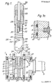
- the connector element 1 comprises a hollow cylindrical body member 2 having a port 3 through which six in the particular embodiment being described of which only two are visible in Fig. 1, optical fibres 4 extend into an output connection 5, as illustrated in Fig. 1, which includes a flange 6 via which it is bolted to the body member 2.
- the output connection may comprise a member projecting from an element to be operated, for example a valve, alternatively it may comprise a fibre optic cable which leads to a number of elements to be operated.
- a cylinder member 7 Arranged generally coaxially with the body member 2 is a cylinder member 7.
- Each of the optical fibres 4 has an expanded beam termination 8 at one end and is secured in a respective radial bore in the cylinder 7 with the external lens face 9 of the termination disposed at the inner cylindrical surface 10 of the cylinder member 7 (Fig. la).
- a piston 11 Inside the cylinder member 7 is slidably disposed a piston 11 which has a flange 12.
- the surface 10 is twice stepped and at one step provides a stop 13 against which the piston flange 12 abuts in the fully extended position of the piston 11 illustrated in Fig. 1.
- an end plate 14 To the lower (in Fig. 1) end of the cylinder member 7 is bolted an end plate 14.
- the cylinder member/end plate assembly is secured to the lower (in Fig. 1) end of the body member 2.
- a centrally-apertured end plate 15 is secured to the upper end of the body member 2, a portion of the cylinder member projecting through the central aperture.
- a coiled spring 16 is disposed in the cylinder member 7 and serves to urge the piston 11 upwards into the position illustrated with its flange abutting the stop 13.
- the piston 11 has two circumferential grooves 17 in each of which is disposed a ring seal 18 which seals serve to protect the lens faces 9 and also to clean them by a wiping action when the two connector elements are joined, as will be further described in the following.
- the optical fibres 4 extend in the cavity 19 between the cylinder member 7 and the body member from the termination 8 to the output connection 5.
- the dimensions of the cavity 19 are such that the curvature of the optical fibres does not exceed the minimum bend radius.
- the cavity 19 is filled with a material such as silicone gel. Bores 20 in the end plate 14 allow for pressure equalisation however due to the nature of the silicone gel it will not drain from the cavity. Bores 21 in the end plate 14 mean that sea water can enter the cylinder member 7 and will be displaced therefrom upon movement of the piston 11 during connection of the connector elements.
- the piston 11 includes a central spring locating portion 22, the opposite end of the spring being located in a locating recess 23 in the end plate 14.
- the portion of the cylinder member 7 projecting through the central aperture of the end plate 15 is comprised of four elements, a pair of diametrically opposed members 24 and a pair of diametrically opposed members 25.
- the members 24 are axially longer than the members 25 and each has a V-sectioned slot 26 which provide radial and height location during connection of two connector elements, as will be described hereinafter.
- the members 25 have radial bores in which are secured locating pins 27 which project towards one another. See also Fig. 3.
- the connector element 1 comprises a female element whereas the other connector element 28 comprises a male element which can be connected to or disconnected from the element 1 underwater.
- the connector element 28 comprises a body element 29 whose lowermost portion (in Fig. 1) has a cylindrical outer surface 30 whereas its uppermost portion is shaped so as to provide an abutment shoulder 31 for a spring 32 and anchoring means 33 for an overmoulding 34.
- a single axial bore 35 Through the uppermost portion of body element 29 and partway into the lowermost portion extends a single axial bore 35, which may be stepped as shown.
- An axial bore 36 (Fig. 2) extends partway into the lowermost portion from the lower end.
- the bores 35 and 36 are interconnected by six, in the case of a six fibre connector, bores 37 which are disposed on the periphery of a circle as indicated in Fig.
- a cross bore 38 through the lowermost portion of body element 29 with which they do not communicate.
- the axial bore 36 is partially closed by means of an end piece 39 (Fig. 2) having a spigot portion 40 which projects into bore 36 and a collar portion 41 which abuts the lowermost end of the body element 29.
- the end piece 39 is secured to the body element 29 by means of a pin 42 extending through radial bores therein as indicated.
- a sleeve member 43 Slidably disposed on the cylindrical outer surface 30 of body element 29 is a sleeve member 43 which has two part-helical slots 44 of opposite inclination.
- a pin 45 extends through the cross bore 38 and each end thereof is located in a respective one of the part-helical slots 44.
- the spring 32 is disposed between the sleeve member 43 and the shoulder 31 and in the unconnected state of the connector elements 1 and 28 urges the sleeve member 43 to the fully extended position shown in Fig. 1 with the uppermost end of the slots 44 engaging the pin 45.
- the sleeve member has a two oppositely disposed external part circumferential grooves 46, see also Fig.3, which have communicating axial entry grooves 47, see Fig. 2.
- the pins 27 are arranged in the grooves 46 in the connected state of the connector elements.
- Six optical fibres 52 extend to the cavity 53 defined between body element 29 and end piece 39 via the bores 37.
- Each of the fibres 52 has a respective expanded beam termination 54 at one end and is secured in a respective radial bore in the body portion 29 with the external lens face 56 of the termination disposed at the cylindrical outer surface 30.
- the sleeve member 43 has an internal circumferential groove in which is disposed a ring seal 58 which serves to clean the lens faces 56 by a wiping action when the two connector elements are joined, as will be further described hereinafter.
- the ring seal 58 In the unconnected state of the connector element 28 the ring seal 58 is disposed below the lens faces 55 as is apparent from Fig.l.
- the ring seals 18 and 58 have a generally X-shaped cross-section as shown in Fig. la.
- the end of a cable 59 including fibres 52 is prepared so that a length of the fibres 52 protrudes from the end of the cable sheath.
- the cable end is inserted in the bore 35 of body element 29 so that each of the fibres 52 extends in a respective one of bores 37 and out of bore 36 at the lower end of the body element 29.
- An expanded beam termination 54 is fitted to each fibre end and then secured in its respective radial bore.
- the cable end is secured to the uppermost end of body element 29 by the overmoulding 34.
- the cavity 53 is filled with silicone gel and the end piece 39 is inserted in bore 36 and secured by means of pin 42.
- the spring 32 is located on outer surface 30, together with the sleeve member 43 which is then secured to body member 29 by pin 45 extending through cross bore 38 and slots 44. Pin 45 is maintained in this position relative to body member 29 and sleeve member 43 for example by a grab screw.
- the connector element 28 For connection of the anchored connector element 1 and the connector element 28 mounted to the end of cable 59 the connector element 28 is axially aligned with the cylinder member 7, with the entry grooves 47 of sleeve member 43 aligned with pins 27, and pushed downwards.
- the body element 29 and end piece 39 move into bore of the cylinder member 7 pushing the piston 11 downwards against the face of the spring 16.
- the lens faces 9 are wiped by the uppermost ring seal 18.
- the sleeve member 43 rides up the outer surface 30 of body member 29 wiping the lens faces 6 with the ring seal 58 as it does so.
- the part-helical grooves 44 cause the sleeve member 43 to be rotated during the insertion of the connector element 28 into connector element 1 with each pin 27 disposed in the respective part-circumferential grooves 46 and thus locking the connector elements 1 and 28 together.
- the various elements are dimensioned such that when locking is achieved and the pins 27 are at the closed ends of the grooves 46 the ends of the pin 45 are located in the grooves of members 24 and at the lower end of the part-helical slots 44 then the lens faces 9 and 56 are aligned (see Fig. 3).
- the springs 16 and 32 are compressed in the connected state and thus serve to maintain the elements in the connected state.
- the sleeve member For disconnection of the connected elements 1 and 28 the sleeve member is rotated to realign the entry grooves with the pins 27, this rotation simultaneously causing the body member 29 to be pulled out of the cylinder member 7 and back into sleeve member 43 by virtue of the action of the pin 45 and slots 44 and of the spring 32.
- the lens faces 56 are reprotected by the ring seal 58 before actual disconnection of the elements 1 and 28 occurs.
- the lens faces 9 are also reprotected by the ring seals 18 before actual disconnection occurs due to in part to the force of the spring 16 pushing the piston 11 upwards.
- connection of the connector elements 1 and 28 merely requires alignment of the two elements and pushing of element 28 into element 1, the sleeve 43 not being held for this operation, whereas disconnection merely requires rotation of the sleeve 43 for unlocking the connector body 29 not being held for this operation, followed by withdrawal of connector element 1.
- the connector may be termed a radial connector since the generally axial, with respect to the cable 59, optical fibres extend in a radial direction for the actual optical connection, that is at the lower end of the body member 29. This radial configuration means that the lenses can be wiped automatically by the relative axial movement between the connector elements.
Landscapes
- Physics & Mathematics (AREA)
- General Physics & Mathematics (AREA)
- Optics & Photonics (AREA)
- Mechanical Coupling Of Light Guides (AREA)
- External Artificial Organs (AREA)
- Separation Using Semi-Permeable Membranes (AREA)
Applications Claiming Priority (2)
| Application Number | Priority Date | Filing Date | Title |
|---|---|---|---|
| GB08427178A GB2166261B (en) | 1984-10-26 | 1984-10-26 | Optical fibre connector |
| GB8427178 | 1984-10-26 |
Publications (2)
| Publication Number | Publication Date |
|---|---|
| EP0183357A2 true EP0183357A2 (fr) | 1986-06-04 |
| EP0183357A3 EP0183357A3 (fr) | 1987-07-29 |
Family
ID=10568828
Family Applications (1)
| Application Number | Title | Priority Date | Filing Date |
|---|---|---|---|
| EP85307133A Withdrawn EP0183357A3 (fr) | 1984-10-26 | 1985-10-04 | Connecteur pour fibres optiques |
Country Status (4)
| Country | Link |
|---|---|
| EP (1) | EP0183357A3 (fr) |
| AU (1) | AU4856985A (fr) |
| GB (1) | GB2166261B (fr) |
| NO (1) | NO853989L (fr) |
Cited By (2)
| Publication number | Priority date | Publication date | Assignee | Title |
|---|---|---|---|---|
| EP0297439A3 (en) * | 1987-06-30 | 1990-07-11 | American Telephone And Telegraph Company | Optical fiber connector |
| CN119535684A (zh) * | 2024-05-27 | 2025-02-28 | 宁波东方电缆股份有限公司 | 一种水下湿插拔连接装置 |
Families Citing this family (8)
| Publication number | Priority date | Publication date | Assignee | Title |
|---|---|---|---|---|
| FR2682487A1 (fr) * | 1991-10-14 | 1993-04-16 | Eca | Connecteur optique, notamment sous-marin. |
| US5645438A (en) * | 1995-01-20 | 1997-07-08 | Ocean Design, Inc. | Underwater-mateable connector for high pressure application |
| US5738535A (en) * | 1996-03-07 | 1998-04-14 | Ocean Design, Inc. | Underwater connector |
| US9057864B2 (en) | 2013-08-02 | 2015-06-16 | Teledyne Instruments, Inc. | Harsh environment connector with seal closure assisting device |
| US9077099B1 (en) | 2014-03-05 | 2015-07-07 | Teledyne Instruments, Inc. | Harsh environment connector with rotating end seal assembly |
| NO2704553T3 (fr) | 2014-03-27 | 2018-02-03 | ||
| US11217909B2 (en) | 2019-09-16 | 2022-01-04 | Teledyne Instruments, Inc. | Connector suitable for harsh environments |
| US11435536B1 (en) | 2021-07-29 | 2022-09-06 | Teledyne Instruments, Inc. | Latched optical feedthrough system for subsea wellhead penetration using spherical seals |
Family Cites Families (4)
| Publication number | Priority date | Publication date | Assignee | Title |
|---|---|---|---|---|
| FR2464489A1 (fr) * | 1979-08-28 | 1981-03-06 | Socapex | Connecteur de fibres optiques et faisceaux de fibres equipes d'un tel connecteur |
| JPS58106512A (ja) * | 1981-12-21 | 1983-06-24 | Seiko Instr & Electronics Ltd | 光フアイバ−用コネクタ− |
| US4465333A (en) * | 1982-01-15 | 1984-08-14 | Grumman Aerospace Corporation | Electro-optical plug-in interconnection |
| WO1985000899A1 (fr) * | 1983-08-11 | 1985-02-28 | Stiftelsen For Industriell Og Teknisk Forskning Ve | Connecteur optique de fibres |
-
1984
- 1984-10-26 GB GB08427178A patent/GB2166261B/en not_active Expired
-
1985
- 1985-10-04 EP EP85307133A patent/EP0183357A3/fr not_active Withdrawn
- 1985-10-08 NO NO853989A patent/NO853989L/no unknown
- 1985-10-14 AU AU48569/85A patent/AU4856985A/en not_active Abandoned
Cited By (2)
| Publication number | Priority date | Publication date | Assignee | Title |
|---|---|---|---|---|
| EP0297439A3 (en) * | 1987-06-30 | 1990-07-11 | American Telephone And Telegraph Company | Optical fiber connector |
| CN119535684A (zh) * | 2024-05-27 | 2025-02-28 | 宁波东方电缆股份有限公司 | 一种水下湿插拔连接装置 |
Also Published As
| Publication number | Publication date |
|---|---|
| EP0183357A3 (fr) | 1987-07-29 |
| NO853989L (no) | 1986-04-28 |
| GB8427178D0 (en) | 1984-12-05 |
| GB2166261B (en) | 1988-09-07 |
| GB2166261A (en) | 1986-04-30 |
| AU4856985A (en) | 1986-05-01 |
Similar Documents
| Publication | Publication Date | Title |
|---|---|---|
| US4696540A (en) | Optical fibre connector having particular utility for underwater use | |
| EP0885475B1 (fr) | Connecteur immerge | |
| EP0898723B1 (fr) | Connecteur électrique-optique à accouplement immergé | |
| US6017227A (en) | Underwater connector | |
| US6010348A (en) | Field-assembled two-piece snap-fit self-sealed electrical connector | |
| US8025506B2 (en) | Harsh environment rotary joint electrical connector | |
| EP0981772B1 (fr) | Ensemble connecteur sous-marin | |
| EP0183357A2 (fr) | Connecteur pour fibres optiques | |
| EP3080651B1 (fr) | Connecteur optique sous-marin utilisant plusieurs joints | |
| US7618198B2 (en) | Harsh environment connector | |
| US4887883A (en) | Undersea wet-mateable fiber optic connector | |
| EP3028081A1 (fr) | Connecteur fonctionnant dans des environnements hostiles avec dispositif d'aide à la fermeture par joint d'étanchéité | |
| WO2003048827A2 (fr) | Systeme d'etancheite pour raccord | |
| EP3735603B1 (fr) | Dispositif de connexion étanche de circuits dans des environnements contaminés et procédés d'utilisation et de fabrication de celui-ci | |
| US6789952B2 (en) | Connection device for optical fibres | |
| CN115000752A (zh) | 一种带有贯通式补偿通道的耐高压型水密电缆接插件 | |
| EP0465464B1 (fr) | Raccord de fibres optiques | |
| US6309112B1 (en) | Easy-to-clean optical connector system | |
| US12287517B2 (en) | Fibre optic wet mate connector system | |
| US5146523A (en) | Alveolar connector comprising at least one connection device for fiber optics | |
| GB2166185A (en) | Locking arrangement for connectors | |
| SU934150A1 (ru) | Быстроразъемное соединение трубчатых элементов |
Legal Events
| Date | Code | Title | Description |
|---|---|---|---|
| PUAI | Public reference made under article 153(3) epc to a published international application that has entered the european phase |
Free format text: ORIGINAL CODE: 0009012 |
|
| AK | Designated contracting states |
Kind code of ref document: A2 Designated state(s): AT BE CH DE FR IT LI LU NL SE |
|
| RAP1 | Party data changed (applicant data changed or rights of an application transferred) |
Owner name: STC PLC |
|
| PUAL | Search report despatched |
Free format text: ORIGINAL CODE: 0009013 |
|
| AK | Designated contracting states |
Kind code of ref document: A3 Designated state(s): AT BE CH DE FR IT LI LU NL SE |
|
| STAA | Information on the status of an ep patent application or granted ep patent |
Free format text: STATUS: THE APPLICATION IS DEEMED TO BE WITHDRAWN |
|
| 18D | Application deemed to be withdrawn |
Effective date: 19880330 |
|
| RIN1 | Information on inventor provided before grant (corrected) |
Inventor name: ADAMS, GRAHAM LEONARD |