EP0183403A2 - Traversées de fils conducteurs dans les pincements - Google Patents
Traversées de fils conducteurs dans les pincements Download PDFInfo
- Publication number
- EP0183403A2 EP0183403A2 EP85307981A EP85307981A EP0183403A2 EP 0183403 A2 EP0183403 A2 EP 0183403A2 EP 85307981 A EP85307981 A EP 85307981A EP 85307981 A EP85307981 A EP 85307981A EP 0183403 A2 EP0183403 A2 EP 0183403A2
- Authority
- EP
- European Patent Office
- Prior art keywords
- lead wire
- titanium
- wire arrangement
- pinch
- arrangement according
- Prior art date
- Legal status (The legal status is an assumption and is not a legal conclusion. Google has not performed a legal analysis and makes no representation as to the accuracy of the status listed.)
- Granted
Links
Images
Classifications
-
- H—ELECTRICITY
- H01—ELECTRIC ELEMENTS
- H01K—ELECTRIC INCANDESCENT LAMPS
- H01K1/00—Details
- H01K1/38—Seals for leading-in conductors
-
- H—ELECTRICITY
- H01—ELECTRIC ELEMENTS
- H01J—ELECTRIC DISCHARGE TUBES OR DISCHARGE LAMPS
- H01J61/00—Gas-discharge or vapour-discharge lamps
- H01J61/02—Details
- H01J61/36—Seals between parts of vessels; Seals for leading-in conductors; Leading-in conductors
- H01J61/366—Seals for leading-in conductors
- H01J61/368—Pinched seals or analogous seals
-
- H—ELECTRICITY
- H01—ELECTRIC ELEMENTS
- H01J—ELECTRIC DISCHARGE TUBES OR DISCHARGE LAMPS
- H01J9/00—Apparatus or processes specially adapted for the manufacture, installation, removal, maintenance of electric discharge tubes, discharge lamps, or parts thereof; Recovery of material from discharge tubes or lamps
- H01J9/24—Manufacture or joining of vessels, leading-in conductors or bases
- H01J9/32—Sealing leading-in conductors
- H01J9/323—Sealing leading-in conductors into a discharge lamp or a gas-filled discharge device
- H01J9/326—Sealing leading-in conductors into a discharge lamp or a gas-filled discharge device making pinched-stem or analogous seals
Definitions
- This invention relates to lead wires used in association with pinch seals in fused silica (quartz), high silica content glass or high melting point aluminosilicate or borosilicate glass or similar materials for achieving electrical connection into a sealed envelope made of the said material.
- the invention is particularly but not exclusively related to tungsten halogen incandescent lamps and to air burning discharge lamps (one example being compact source iodide lamps) using quartz/metal seals for electrical lead-throughs.
- the so-called pinch-seal in which the internal electrical connections of the lamp and the external or outer lead wire are both welded to a length of foil usually molybdenum which is placed within a tube of the envelope material which is then heated and pinched between suitable pinching apparatus including pinching jaws and a die block support.
- the foil may be feather edged.
- This method of sealing is particularly suitable where the envelope material is pure fused silica or similar materials with a silica content of greater than 96% (such as the material known by the Registered Trade Mark VYCOR) as is necessary for tungsten halogen cycle incandescent lamps.
- Temperatures of the envelope material surrounding the foil and leadwire assembly during the pinch sealing process can momentarily reach 2000 C. Consequently it is conventional to use an external lead wire of a highly refractory material, typically molybdenum (melting point 2430 C).
- a lead wire arrangement for sealing in a pinch seal including a sealing foil having joined thereto an outer lead wire which is, at least at the surface, made of an oxidation resistant material having a melting point lower than the temperature surrounding the foil and lead wire arrangement during a pinch sealing process.
- the oxidation resistant material has a melting point lower than 2000 o C because this is a temperature commonly reached during pinch sealing.
- a lead wire arrangement in a pinch seal including a hermetic sealing member having joined thereto an outer lead wire which is, at least, at the surface made of titanium or a suitable titanium alloy. Titanium being a preferred material because it is so readily obtainable.
- a method of pinch sealing which includes the step of using for the outer lead wire a material which is oxidation resistant and has a melting point lower than the temperature surrounding the foil and lead wire during a pinch sealing prooess.
- the method of pinch sealing referred to in this invention has to be distinguished from other methods of sealing, for example the method of sealing disclosed in UK Patent 776,972, published June 12, 1957.
- UK Patent 776,972 discloses the use of titanium as a sealing element in a hermetic glass to metal seal wherein the coefficient of expansion of the metal must be matched to the glass and the technique is restricted to low melting point glasses and sealing temperatures of around 500 C.
- Pinch sealing is a non matched foil type seal which requires the adhesion forces at the quartz/metal interface to withstand the expansion and contractions stresses in the thin section foil.
- pinch seals are made with lamp envelope materials containing in excess of 95% silica and almost negligible expansion, for example, less than 8 x 10 -7 °C -1 .
- the sealing temperature can reach 2000 C. It especially has to be borne in mind that, in the present invention, the titanium is being used for the outer lead wires and not to form the hermetic part of the seal which is the function of the foil.
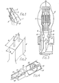
- Figure 1 shows a pinch seal of a quartz lamp envelope 1 in this case having two lead-ins at one end although one or more may be provided.
- the internal electrical connections 2 are welded to molybdenum foils 3 to which are also welded external lead wires 4. These are sealed- in the pinch 5.
- Non highly refractory materials are suitable, including titanium, NILO K, and Fecralloy (the latter two being commercial nickel/iron alloys). This is a surprising result since all these materials melt at temperatures in the region of 1350 o C to 1670°C which is relatively low in comparison to the pinching temperature and melting point of molybdenum and would not normally be expected to survive the pinching process. Titanium is preferred to either NILO K or Fecralloy because of its slightly higher melting point. On the other hand NILO K and Fecralloy are advantageous in having a lower resistivity than titanium.
- the invention may be used with solid titanium wire or conventional molybdenum wire plated with titanium which would give considerable cost savings. It will be appreciated that materials other than those specified with similar melting points and suitable thermal masses may be used.
- references to the surface of the lead wire being of titanium or similar material is intended to include surface coatings of thickness 0.05mm or less where the coating is of metals such as platinum or nickel or for a non-metal refractory material, such as alumina, the coating thickness would be 0.25mm or less.
- FIG. 2 illustrates pinch seal arrangements in accordance with the invention and having dimensions in accordance with the following table:
- the outer lead wire was made of an alloy of titanium and molybdenum.
- An alloy of 85% by weight of titanium and 15% by weight of molybdenum was particularly useful because it reduced the tendency of the quartz to stick to the outer lead wire material. This in turn lessened the possibility of inter facial cracking. Also the presence of molydenum was found to give a useful small increase inthe melting temperature of the alloy compared to pure titanium.
- Figure 3 illustrates an example of a typical single ended tungsten halogen incandescent lamp having a quartz envelope 6, filament 7 and pinch seal arrangement 8 including inner lead wires 9 attached to molybdenum foil seal members 10.
- outer lead wires 11, attached to respective foils 10 are each made of titanium wire.
- Figure 4 illustrates an example of one end section of a typical quartz linear tungsten halogen incandescent lamp.
- This comprises quartz envelope 12, linear filament 13 with tungsten spiral support 14, pinch seal arrangement 15, including inner lead wire 16 attached to molybdenum foil seal member 17.
- outer lead wire 18 attached to foil 17 is made of titanium wire.
Landscapes
- Engineering & Computer Science (AREA)
- Manufacturing & Machinery (AREA)
- Vessels And Coating Films For Discharge Lamps (AREA)
- Insulated Conductors (AREA)
- Cable Accessories (AREA)
- Installation Of Indoor Wiring (AREA)
- Wire Bonding (AREA)
- Seal Device For Vehicle (AREA)
Priority Applications (1)
| Application Number | Priority Date | Filing Date | Title |
|---|---|---|---|
| AT85307981T ATE65642T1 (de) | 1984-11-24 | 1985-11-04 | Dichtungsdraehte in klemmungen. |
Applications Claiming Priority (2)
| Application Number | Priority Date | Filing Date | Title |
|---|---|---|---|
| GB8429740 | 1984-11-24 | ||
| GB848429740A GB8429740D0 (en) | 1984-11-24 | 1984-11-24 | Lead wires in pinch seals |
Publications (3)
| Publication Number | Publication Date |
|---|---|
| EP0183403A2 true EP0183403A2 (fr) | 1986-06-04 |
| EP0183403A3 EP0183403A3 (en) | 1988-11-17 |
| EP0183403B1 EP0183403B1 (fr) | 1991-07-24 |
Family
ID=10570231
Family Applications (1)
| Application Number | Title | Priority Date | Filing Date |
|---|---|---|---|
| EP85307981A Expired - Lifetime EP0183403B1 (fr) | 1984-11-24 | 1985-11-04 | Traversées de fils conducteurs dans les pincements |
Country Status (5)
| Country | Link |
|---|---|
| US (1) | US4739219A (fr) |
| EP (1) | EP0183403B1 (fr) |
| AT (1) | ATE65642T1 (fr) |
| DE (1) | DE3583585D1 (fr) |
| GB (1) | GB8429740D0 (fr) |
Cited By (6)
| Publication number | Priority date | Publication date | Assignee | Title |
|---|---|---|---|---|
| EP0375402A3 (fr) * | 1988-12-21 | 1991-03-27 | Gte Products Corporation | Enveloppe en quartz pour lampe avec feuille en molybdène pourvue d'une surface résistant à l'oxydation réalisée par implantation ionique |
| EP0369371A3 (fr) * | 1988-11-15 | 1991-06-19 | Patent-Treuhand-Gesellschaft für elektrische Glühlampen mbH | Procédé pour fabriquer une ampoule de lampe |
| EP0451647A3 (en) * | 1990-04-12 | 1992-03-11 | Patent-Treuhand-Gesellschaft Fuer Elektrische Gluehlampen Mbh | High-pressure discharge lamp and method for its manufacture |
| EP0475381A3 (en) * | 1990-09-11 | 1992-09-30 | Gte Products Corporation | Arc lamp assembly with containment means |
| EP0657912A3 (fr) * | 1993-12-08 | 1996-11-20 | Ushio Electric Inc | Procédé de connection d'une feuille de molybdène à une portion d'un conducteur de molybdène et méthode de production d'une pièce de lampe hermétiquement incluse utilisant ledit procédé. |
| WO1997045859A3 (fr) * | 1996-05-31 | 1998-01-29 | Philips Electronics Nv | Lampe a decharge a pression elevee |
Families Citing this family (12)
| Publication number | Priority date | Publication date | Assignee | Title |
|---|---|---|---|---|
| US5252888A (en) * | 1991-12-30 | 1993-10-12 | Gte Products Corporation | Lamp capsule support base |
| JP4388699B2 (ja) * | 1998-08-13 | 2009-12-24 | コーニンクレッカ フィリップス エレクトロニクス エヌ ヴィ | コーティングされた外部電流導体を有する電気ランプ |
| US6515421B2 (en) * | 1999-09-02 | 2003-02-04 | General Electric Company | Control of leachable mercury in fluorescent lamps |
| AT4408U1 (de) * | 2000-05-18 | 2001-06-25 | Plansee Ag | Verfahren zur herstellung einer elektrischen lampe |
| US6771013B2 (en) * | 2000-10-17 | 2004-08-03 | Fei Company | Low power schottky emitter |
| US7153179B2 (en) * | 2002-11-07 | 2006-12-26 | Advanced Lighting Technologies, Inc. | Oxidation-protected metallic foil and method |
| US8277274B2 (en) | 2002-11-07 | 2012-10-02 | Advanced Lighting Technologies, Inc. | Apparatus and methods for use of refractory abhesives in protection of metallic foils and leads |
| USD581064S1 (en) * | 2007-03-02 | 2008-11-18 | Panasonic Corporation | Lamp filament |
| USD581063S1 (en) * | 2007-03-02 | 2008-11-18 | Panasonic Corporation | Filament for lamp |
| USD580562S1 (en) * | 2007-03-02 | 2008-11-11 | Panasonic Corporation | Filament for lamp |
| US8134294B2 (en) * | 2010-05-25 | 2012-03-13 | General Electric Company | Low pressure discharge lamps with coated inner wires for improved lumen maintenance |
| US11303533B2 (en) | 2019-07-09 | 2022-04-12 | Cisco Technology, Inc. | Self-healing fabrics |
Family Cites Families (13)
| Publication number | Priority date | Publication date | Assignee | Title |
|---|---|---|---|---|
| GB776972A (en) * | 1953-11-27 | 1957-06-12 | British Thomson Houston Co Ltd | Improvements relating to glass-to-metal seals |
| GB882190A (en) * | 1959-07-14 | 1961-11-15 | Gen Electric Co Ltd | Improvements in or relating to envelopes for electrical devices |
| BE634513A (fr) * | 1962-07-06 | |||
| US3515420A (en) * | 1968-09-26 | 1970-06-02 | Gen Electric | Quartz to metal seal for electrical devices |
| US3668391A (en) * | 1970-08-19 | 1972-06-06 | Sylvania Electric Prod | Tungsten halogen lamp having improved seal of molybdenum aluminide |
| US3668456A (en) * | 1970-08-28 | 1972-06-06 | Sylvania Electric Prod | Lamp having improved press seal |
| US4039883A (en) * | 1972-07-04 | 1977-08-02 | U.S. Philips Corporation | Soldered joint |
| NL7501272A (nl) * | 1975-02-04 | 1976-08-06 | Philips Nv | Electrische lamp. |
| US4070594A (en) * | 1975-02-13 | 1978-01-24 | Matsushita Electronics Corporation | Light source device to be utilized mainly for projection purposes |
| FR2300745A1 (fr) * | 1975-02-17 | 1976-09-10 | Lampes Elect Fab Reunies | Procede de scellement verre metal resistant a haute temperature en atmosphere oxydante |
| GB1551734A (en) * | 1975-06-02 | 1979-08-30 | Thorn Electrical Ind Ltd | Seals for electric devices eg lamps |
| DE2713702B2 (de) * | 1977-03-28 | 1979-10-31 | Heimann Gmbh, 6200 Wiesbaden | Gasentladungslampe |
| NL183613B (nl) * | 1978-03-15 | 1988-07-01 | Philips Nv | Elektrische lamp. |
-
1984
- 1984-11-24 GB GB848429740A patent/GB8429740D0/en active Pending
-
1985
- 1985-11-04 EP EP85307981A patent/EP0183403B1/fr not_active Expired - Lifetime
- 1985-11-04 DE DE8585307981T patent/DE3583585D1/de not_active Expired - Lifetime
- 1985-11-04 AT AT85307981T patent/ATE65642T1/de not_active IP Right Cessation
-
1987
- 1987-07-29 US US07/080,141 patent/US4739219A/en not_active Expired - Lifetime
Cited By (7)
| Publication number | Priority date | Publication date | Assignee | Title |
|---|---|---|---|---|
| EP0369371A3 (fr) * | 1988-11-15 | 1991-06-19 | Patent-Treuhand-Gesellschaft für elektrische Glühlampen mbH | Procédé pour fabriquer une ampoule de lampe |
| EP0375402A3 (fr) * | 1988-12-21 | 1991-03-27 | Gte Products Corporation | Enveloppe en quartz pour lampe avec feuille en molybdène pourvue d'une surface résistant à l'oxydation réalisée par implantation ionique |
| EP0451647A3 (en) * | 1990-04-12 | 1992-03-11 | Patent-Treuhand-Gesellschaft Fuer Elektrische Gluehlampen Mbh | High-pressure discharge lamp and method for its manufacture |
| US5142195A (en) * | 1990-04-12 | 1992-08-25 | Patent Treuhand Gesellschaft Fur Elektrische Gluhlampen M.B.H. | Pinch-sealed high pressure discharge lamp, and method of its manufacture |
| EP0475381A3 (en) * | 1990-09-11 | 1992-09-30 | Gte Products Corporation | Arc lamp assembly with containment means |
| EP0657912A3 (fr) * | 1993-12-08 | 1996-11-20 | Ushio Electric Inc | Procédé de connection d'une feuille de molybdène à une portion d'un conducteur de molybdène et méthode de production d'une pièce de lampe hermétiquement incluse utilisant ledit procédé. |
| WO1997045859A3 (fr) * | 1996-05-31 | 1998-01-29 | Philips Electronics Nv | Lampe a decharge a pression elevee |
Also Published As
| Publication number | Publication date |
|---|---|
| US4739219A (en) | 1988-04-19 |
| EP0183403A3 (en) | 1988-11-17 |
| GB8429740D0 (en) | 1985-01-03 |
| ATE65642T1 (de) | 1991-08-15 |
| EP0183403B1 (fr) | 1991-07-24 |
| DE3583585D1 (de) | 1991-08-29 |
Similar Documents
| Publication | Publication Date | Title |
|---|---|---|
| US4739219A (en) | Electric lamp with pinch sealed outer conductor of non-highly refractory material | |
| AU604967B2 (en) | Increasing the oxidation resistance of molybdenum and its use for lamp seals | |
| EP0136505B1 (fr) | Scellement direct entre niobium et céramique | |
| US2163409A (en) | Ceramic-to-metal seal | |
| EP0133764A1 (fr) | Lampe á indendescence | |
| WO1994003923A1 (fr) | Traversees etanches en alliage actif conducteur | |
| US2163410A (en) | Ceramic-to-metal seal | |
| US7955153B2 (en) | Compound body and a process for the production of a mechanical connection | |
| EP0178700A1 (fr) | Lampe électrique et composition de verre | |
| US2163408A (en) | Vacuum-tight seal | |
| EP0160316B1 (fr) | Lampe à décharge à haute intensité et à bout unique et fabrication | |
| KR20040051536A (ko) | 적외선 방사원 | |
| US5515412A (en) | Method of producing frit-sealed x-ray tube | |
| US4668204A (en) | Single-ended high intensity discharge lamp and manufacture | |
| US5528105A (en) | Copper-steel composite lead wire and use in incandescent filament electric lamps | |
| EP0657912B1 (fr) | Procédé de connection d'une feuille de molybdène à une portion d'un conducteur de molybdène et méthode de production d'une pièce de lampe hermétiquement incluse utilisant ledit procédé | |
| GB1583846A (en) | Closing of electric discharge tubes | |
| US3598435A (en) | Ceramic-metal bonding composition and composite article of manufacture | |
| US1154081A (en) | Leading-in conductor. | |
| JPS6135661B2 (fr) | ||
| JPS5929349A (ja) | せん光管およびその製造方法 | |
| CA1095576A (fr) | Conducteur de lampes en fils de cuivre renforces par dispersion | |
| EP0495588A2 (fr) | Matériau auxiliaire pour soudage | |
| JPS62190649A (ja) | メタルハライドランプ | |
| GB1568626A (en) | Bonding substrates to alumina ceramics |
Legal Events
| Date | Code | Title | Description |
|---|---|---|---|
| PUAI | Public reference made under article 153(3) epc to a published international application that has entered the european phase |
Free format text: ORIGINAL CODE: 0009012 |
|
| AK | Designated contracting states |
Kind code of ref document: A2 Designated state(s): AT BE DE FR GB IT NL |
|
| PUAL | Search report despatched |
Free format text: ORIGINAL CODE: 0009013 |
|
| AK | Designated contracting states |
Kind code of ref document: A3 Designated state(s): AT BE DE FR GB IT NL |
|
| 17P | Request for examination filed |
Effective date: 19890511 |
|
| 17Q | First examination report despatched |
Effective date: 19890814 |
|
| GRAA | (expected) grant |
Free format text: ORIGINAL CODE: 0009210 |
|
| AK | Designated contracting states |
Kind code of ref document: B1 Designated state(s): AT BE DE FR GB IT NL |
|
| REF | Corresponds to: |
Ref document number: 65642 Country of ref document: AT Date of ref document: 19910815 Kind code of ref document: T |
|
| PGFP | Annual fee paid to national office [announced via postgrant information from national office to epo] |
Ref country code: GB Payment date: 19910806 Year of fee payment: 7 |
|
| ITF | It: translation for a ep patent filed | ||
| REF | Corresponds to: |
Ref document number: 3583585 Country of ref document: DE Date of ref document: 19910829 |
|
| PGFP | Annual fee paid to national office [announced via postgrant information from national office to epo] |
Ref country code: AT Payment date: 19910918 Year of fee payment: 7 |
|
| PGFP | Annual fee paid to national office [announced via postgrant information from national office to epo] |
Ref country code: FR Payment date: 19910927 Year of fee payment: 7 |
|
| ET | Fr: translation filed | ||
| PGFP | Annual fee paid to national office [announced via postgrant information from national office to epo] |
Ref country code: BE Payment date: 19911106 Year of fee payment: 7 |
|
| PGFP | Annual fee paid to national office [announced via postgrant information from national office to epo] |
Ref country code: NL Payment date: 19911130 Year of fee payment: 7 |
|
| PGFP | Annual fee paid to national office [announced via postgrant information from national office to epo] |
Ref country code: DE Payment date: 19920117 Year of fee payment: 7 |
|
| PLBE | No opposition filed within time limit |
Free format text: ORIGINAL CODE: 0009261 |
|
| STAA | Information on the status of an ep patent application or granted ep patent |
Free format text: STATUS: NO OPPOSITION FILED WITHIN TIME LIMIT |
|
| 26N | No opposition filed | ||
| PG25 | Lapsed in a contracting state [announced via postgrant information from national office to epo] |
Ref country code: GB Effective date: 19921104 Ref country code: AT Effective date: 19921104 |
|
| PG25 | Lapsed in a contracting state [announced via postgrant information from national office to epo] |
Ref country code: BE Effective date: 19921130 |
|
| BERE | Be: lapsed |
Owner name: THORN EMI P.L.C. Effective date: 19921130 |
|
| PG25 | Lapsed in a contracting state [announced via postgrant information from national office to epo] |
Ref country code: NL Effective date: 19930601 |
|
| GBPC | Gb: european patent ceased through non-payment of renewal fee |
Effective date: 19921104 |
|
| NLV4 | Nl: lapsed or anulled due to non-payment of the annual fee | ||
| PG25 | Lapsed in a contracting state [announced via postgrant information from national office to epo] |
Ref country code: FR Effective date: 19930730 |
|
| PG25 | Lapsed in a contracting state [announced via postgrant information from national office to epo] |
Ref country code: DE Effective date: 19930803 |
|
| REG | Reference to a national code |
Ref country code: FR Ref legal event code: ST |