EP0183459A2 - Dach und Methode, ein Gebäude mit einem Dach zu versehen - Google Patents
Dach und Methode, ein Gebäude mit einem Dach zu versehen Download PDFInfo
- Publication number
- EP0183459A2 EP0183459A2 EP85308370A EP85308370A EP0183459A2 EP 0183459 A2 EP0183459 A2 EP 0183459A2 EP 85308370 A EP85308370 A EP 85308370A EP 85308370 A EP85308370 A EP 85308370A EP 0183459 A2 EP0183459 A2 EP 0183459A2
- Authority
- EP
- European Patent Office
- Prior art keywords
- roof
- panel
- strip
- sub
- panels
- Prior art date
- Legal status (The legal status is an assumption and is not a legal conclusion. Google has not performed a legal analysis and makes no representation as to the accuracy of the status listed.)
- Withdrawn
Links
- 238000000034 method Methods 0.000 title claims abstract description 20
- 239000003566 sealing material Substances 0.000 claims abstract description 26
- 238000007789 sealing Methods 0.000 claims abstract description 3
- 239000011152 fibreglass Substances 0.000 claims description 57
- 239000000463 material Substances 0.000 claims description 42
- 230000000452 restraining effect Effects 0.000 claims description 17
- 239000007788 liquid Substances 0.000 claims description 15
- 239000004589 rubber sealant Substances 0.000 claims description 6
- 238000010276 construction Methods 0.000 description 6
- 239000012858 resilient material Substances 0.000 description 6
- 229910000831 Steel Inorganic materials 0.000 description 5
- 239000003054 catalyst Substances 0.000 description 5
- 239000011248 coating agent Substances 0.000 description 5
- 238000000576 coating method Methods 0.000 description 5
- 239000011347 resin Substances 0.000 description 5
- 229920005989 resin Polymers 0.000 description 5
- 239000011090 solid board Substances 0.000 description 5
- 239000010959 steel Substances 0.000 description 5
- 238000011065 in-situ storage Methods 0.000 description 4
- 239000011810 insulating material Substances 0.000 description 3
- XEEYBQQBJWHFJM-UHFFFAOYSA-N Iron Chemical compound [Fe] XEEYBQQBJWHFJM-UHFFFAOYSA-N 0.000 description 2
- 239000004677 Nylon Substances 0.000 description 2
- 238000009833 condensation Methods 0.000 description 2
- 230000005494 condensation Effects 0.000 description 2
- 230000000694 effects Effects 0.000 description 2
- 239000002184 metal Substances 0.000 description 2
- 229910052751 metal Inorganic materials 0.000 description 2
- 229920001778 nylon Polymers 0.000 description 2
- 230000002093 peripheral effect Effects 0.000 description 2
- 239000007787 solid Substances 0.000 description 2
- 230000015572 biosynthetic process Effects 0.000 description 1
- 239000002131 composite material Substances 0.000 description 1
- 230000009977 dual effect Effects 0.000 description 1
- 238000002474 experimental method Methods 0.000 description 1
- 239000006260 foam Substances 0.000 description 1
- 239000006261 foam material Substances 0.000 description 1
- 238000010438 heat treatment Methods 0.000 description 1
- 239000012212 insulator Substances 0.000 description 1
- 229910052742 iron Inorganic materials 0.000 description 1
- 239000012528 membrane Substances 0.000 description 1
- 239000012466 permeate Substances 0.000 description 1
- 239000004033 plastic Substances 0.000 description 1
- 229920003023 plastic Polymers 0.000 description 1
- 229920000728 polyester Polymers 0.000 description 1
- 230000035939 shock Effects 0.000 description 1
- XLYOFNOQVPJJNP-UHFFFAOYSA-N water Substances O XLYOFNOQVPJJNP-UHFFFAOYSA-N 0.000 description 1
Images


Classifications
-
- E—FIXED CONSTRUCTIONS
- E04—BUILDING
- E04D—ROOF COVERINGS; SKY-LIGHTS; GUTTERS; ROOF-WORKING TOOLS
- E04D3/00—Roof covering by making use of flat or curved slabs or stiff sheets
- E04D3/35—Roofing slabs or stiff sheets comprising two or more layers, e.g. for insulation
- E04D3/351—Roofing slabs or stiff sheets comprising two or more layers, e.g. for insulation at least one of the layers being composed of insulating material, e.g. fibre or foam material
-
- E—FIXED CONSTRUCTIONS
- E04—BUILDING
- E04D—ROOF COVERINGS; SKY-LIGHTS; GUTTERS; ROOF-WORKING TOOLS
- E04D13/00—Special arrangements or devices in connection with roof coverings; Protection against birds; Roof drainage ; Sky-lights
- E04D13/16—Insulating devices or arrangements in so far as the roof covering is concerned, e.g. characterised by the material or composition of the roof insulating material or its integration in the roof structure
- E04D13/1606—Insulation of the roof covering characterised by its integration in the roof structure
- E04D13/1612—Insulation of the roof covering characterised by its integration in the roof structure the roof structure comprising a supporting framework of roof purlins or rafters
- E04D13/1618—Insulation of the roof covering characterised by its integration in the roof structure the roof structure comprising a supporting framework of roof purlins or rafters with means for fixing the insulating material between the roof covering and the upper surface of the roof purlins or rafters
-
- E—FIXED CONSTRUCTIONS
- E04—BUILDING
- E04D—ROOF COVERINGS; SKY-LIGHTS; GUTTERS; ROOF-WORKING TOOLS
- E04D13/00—Special arrangements or devices in connection with roof coverings; Protection against birds; Roof drainage ; Sky-lights
- E04D13/17—Ventilation of roof coverings not otherwise provided for
-
- E—FIXED CONSTRUCTIONS
- E04—BUILDING
- E04D—ROOF COVERINGS; SKY-LIGHTS; GUTTERS; ROOF-WORKING TOOLS
- E04D3/00—Roof covering by making use of flat or curved slabs or stiff sheets
- E04D3/35—Roofing slabs or stiff sheets comprising two or more layers, e.g. for insulation
- E04D3/357—Roofing slabs or stiff sheets comprising two or more layers, e.g. for insulation comprising hollow cavities
-
- E—FIXED CONSTRUCTIONS
- E04—BUILDING
- E04D—ROOF COVERINGS; SKY-LIGHTS; GUTTERS; ROOF-WORKING TOOLS
- E04D3/00—Roof covering by making use of flat or curved slabs or stiff sheets
- E04D3/36—Connecting; Fastening
- E04D3/3601—Connecting; Fastening of roof covering supported by the roof structure with interposition of a insulating layer
- E04D3/3603—Connecting; Fastening of roof covering supported by the roof structure with interposition of a insulating layer the fastening means being screws or nails
-
- E—FIXED CONSTRUCTIONS
- E04—BUILDING
- E04D—ROOF COVERINGS; SKY-LIGHTS; GUTTERS; ROOF-WORKING TOOLS
- E04D3/00—Roof covering by making use of flat or curved slabs or stiff sheets
- E04D3/38—Devices for sealing spaces or joints between roof-covering elements
Definitions
- This invention relates to a roof and a method of providing a building with a roof, and is more particularly, although not exclusively, concerned with a roof formed from a single panel which panel is capable of relative movement with respect to a sub-structure of the building, and also with a roof formed from a plurality of panels which are resiliently secured together such that the panels are capable of relative movement with respect to each other and with respect to the substructure of the building.
- Fibreglass in association with a solid board, has also been used as a roofing material as follows.
- a solid board is sold with instructions for coating the solid board with a layer of fibreglass material; thus, fibreglass matting is placed on the board and this is formed into a solid sheet of fibreglass by the use of a resin and a suitable catalyst.
- the layer of fibreglass material formed is continuously bonded to the solid board with the intention of creating a waterproof panel.
- the panels created may be used in the construction of a roof. These panels, which represent a layer of fibreglass material directly bonded to a board, suffer from the disadvantage which arises because of the different coefficients of expansion of the solid board and of the layer of fibreglass. Thus, the fibreglass or the board is likely to crack or blister under extremes of temperature.
- Felt roofs suffer from a number of disadvantages, including the presence of small holes caused when the felt is tacked to the sub-structure of the roof; the small holes may allow water to leak through the roof.
- several layers of felt need to be used, thereby substantially increasing the cost of the roof, Further, the nature of the felt layer prevents any circulation of air within the roof itself and, as a result, moisture may build up giving rise to problems of rot.
- glass-reinforced-plastics for constructing a roof of a building, particularly a flat building is known from GB 2078277A.
- This roof is rigid and allows no relative movement of the panels of the roof.
- Roofs constructed from other materials, such as corrugated iron, are also well known and techniques by which such roofs may be allowed to move relative to the sub-structure of the buildings to which they are attached are known.
- British Patent Specification No. 1553876 discloses a clip which permits side to side movement of the panels of the roof whilst the clip of British Patent Specification No. 1543290 permits up and down movement of the panels of the roof.
- the clips are rigid metal articles and the construction of a roof using such clips is time consuming.
- the strip serves a dual function.
- the strip acts to support the panel along its edge regions, providing a basis about which the panel may flex by virtue of the intermediate layer of the resilient material.
- the strip also serves to hold the panel above the sub-structure of the building such that air may circulate under the panel.
- the roof or roof portion comprises:
- Each panel of the array can, in effect, move slightly in all directions.
- the present roof is capable of moving slightly in response to the wind or any other external influence on the roof.
- the lifetime of the roof of the present invention is considerably increased over prior art roofs because the amount of wear and tear is reduced by virtue of the panel, or panels, of the array being capable of moving slightly.
- the strips are disposed between the array of panels and the sub-structure of the building and, in a preferred embodiment, the periphery of the array is supported and overlapped by a further strip or strips via which the panels are resiliently securable to the substructure.
- the further strip is spaced apart from the peripheral region of the array by an intermediate layer of the resilient material which allows a degree of relative movement between the panel and the strip.
- the roof is resiliently secured to the sub-structure of the building by a fixing means which extends through an aperture in the edge region of the panel and an aperture in the strip, and which is fixed to the sub-structure, whilst allowing said relative movement.
- the fixing means may be, for example, a screw, a bolt, or a pin which extends through the said apertures.
- a sleeve preferably made of nylon, is provided between the aperture of the panel and the aperture of the strip and the fixing means passes through the sleeve.
- the fixing means may comprise a head which has a diameter greater than the diameter of the aperture in the panel such that the head holds the panel down.
- the outer diameter of the screw is less than the inner diameter of the sleeve and the outer diameter of the sleeve is preferably less than the inner diameter of the apertures, such that there are spaces between the apertures, sleeve and fixing means.
- the spaces are preferably filled with the resilient material.
- the resilient material is preferably a rubber sealant.
- the rubber sealant is a liquid prior to assembly of the roof, which liquid sets to a solid form after assembly of the roof.
- One such, presently preferred, rubber sealant is a material known by the Registered Trade Mark SIKAFLEX.
- the panel or panels of the roof may be made of fibreglass.
- the construction of the roof is not to be limited to such a material as many other materials may be used, for example a glass reinforced plastic, other plastics materials, metal or any other suitable rigid or semi-rigid material.
- the roof may be constructed as a "warm roof” in which case an insulating layer is provided between the at least one strip and the sub-structure of the building.
- the insulating layer is preferably a closed cell foam but may be any other form of insulating material.
- the roof of the present invention is generally formed of a single, large panel which large panel is formed of a number of smaller panels joined at their edge regions.
- One advantage of the roof is that it can be constructed in situ.
- the roof may be formed of a number of panels, it is to be appreciated that the roof may comprise a single panel which is resiliently fixed to strips and to a sub-structure of the building along its outer periphery such that the panel is capable of relative movement with respect to the strips and with respect to the sub-structure of the building.
- the roof may be constructed to co-operate with other features of the roof.
- the roof may be designed to accommodate this feature with the feature being sealed into the roof by provision of a hole in a panel of the roof or between adjacent panels of the roof, through which hole the feature extends.
- Around the aperture is preferably placed, to support the edge regions of the panel forming the aperture, a strip, the strip and the edge regions of the aperture being spaced apart by an intermediate layer of the resilient material.
- the edge region of the panel around the aperture is preferably fixed to the substructure of the building by virtue of fixing means extending through holes in the panel and the strip as hereinbefore described.
- the gap between the feature and the panel and strip may be filled with the rubber sealant.
- the roof of the present invention may be applied to flat, domed or low pitched roof structures. Furthermore, the roof may be coated with a layer of polyester flow coating to further seal and waterproof the roof.
- the roof may be installed in wet conditions. By the use of a fireproof insulator, the roof may be constructed to fire safety standards.
- a method of roofing a building which method comprises positioning at least one strip above a sub-structure of the building; providing a liquid sealing material on the at least one strip; disposing a panel over the sealing material on the at least one strip; securing the panel and the at least one strip to the sub-structure of the building by a fixing means which extends through an apertures in the panel and a corresponding aperture in the at least one strip to secure the roof or roof portion to the sub-structure of the building whilst permitting relative movement between the panel and the at least one strip and the sub-structure; and permitting the liquid sealing material to set, thus providing an intermediate resilient layer between the panel and the at least one strip.
- an array of panels are disposed over at least one strip such that adjacent edge regions of adjacent panels overlap the at least one strip; the method further comprising the step of providing a resilient sealing material between the adjacent edges of the panels.
- the panel, or each panel may be coated on its weather side with a waterproof gel coating.
- the method of the present invention allows a roof to be rapidly and efficiently constructed in situ, with sheets of the material from which the panel or panels are constructed being formed at a work shop away from the location of the building to be roofed.
- a presently preferred size of sheet is 8 x 4 ft. (2.5 x 1.25m). Such sheets are approximately 2mm in thickness.
- the strips are preferably constructed in lengths which are about 1 ft (300mm) wide, again constructed as a 2 mm thickness.
- the apertures in the edge regions of the panels and in the strips through which the fixing means extend are conveniently drilled at 2 ft (600 mm) intervals, approximately 3 inches (75 mm) from the edge of the panel or strip.
- the roof, or roof portion, of the first aspect of this invention may further include at least one elastic restraining means inward of the periphery of one or more or all of the panels and connecting the sub-structure and the panel.
- a roof, or a portion of a roof, of a building comprising:
- the panel of fibregalss material may expand in warm weather causing the panel as a whole to form a shallow dome.
- the doming of the panel causes air to be drawn into the space between the sub-structure and the panel, through gaps around the periphery of the panel, and possibly also through the layer immediately below the panel.
- the circulation of air caused by the aforementioned movement of the fibreglass panel serves to prevent any build up of moisture, through condensation, in the space between the panel and the sub-structure.
- the panel of fibreglass material may be secured, at intervals along its periphery, to the sub-structure by means of bolts, tacks or other convenient means. Additionally, the panel may be provided, at its periphery, with a rim, a downwardly extending portion of the rim being secured to the sub-structure. Furthermore, a lip may be provided along at least a portion of the periphery of the panel to extend under existing flashing of the building.
- the panel of fibreglass material may be constructed to cooperate with other features of the roof.
- the panel of fibreglass may be designed to accommodate this feature with the feature being sealed into the roof by the use of a shaped piece of fibreglass matting, a resin and a suitable catalyst whereby the feature is bonded to the main panel of fibreglass material.
- the roof further comprises an insulating layer between the panel of fibreglass material and the sub-structure.
- the insulating layer may comprise a plurality of spaced apart insulating boards which may be manufactured from a composite material which material allows air to permeate therethrough.
- the insulating boards may be arranged on the sub-structure with approximately 6mm gaps between the insulating boards. The gaps allow the circulation of air in the spaces between the panel of fibreglass and the sub-structure.
- the panel of fibreglass material lies directly above the layer of insulating material and may move away from this layer as the panel of fibreglass expands during hot weather.
- roof areas may be covered by a single, unitary panel of fibreglass material.
- This single, unitary panel of fibreglass material may be formed from a plurality of sheets bonded together at adjacent edge regions. This bonding may be effected in situ.
- the roof may also include at least one elastic restraining means, inward of the periphery of the panel, connecting the sub-structure and the panel of fibreglass material, but nonetheless permitting relative movement between the panel and the sub-structure.
- the restraining means may be fixed to the panel of fibreglass material by means of a eye which is fixed to a steel plate cast into the panel of fibreglass material. Attachment to the sub-structure may be by means of a ring bolt which is bolted through the sub-structure or screwed into the sub-structure. Conveniently, the restraining means is formed of a rubber material.
- the panel of fibreglass material may be provided, on the weather side thereof, with a coat of a waterproof gel.
- the roof, or portion of roof, according to the present invention may be a flat, or slightly sloped, roof in which case the entire roof may be covered by a single, unitary flat piece of fibreglass material.
- a single panel of fibreglass may be used to cover each separate sloping face of the roof, with each panel being joined at the ridges of the roof with fibreglass matting, resin and a suitable catalyst.
- a method of roofing a building which method comprises positioning a panel of fibreglass material above a sub-structure, and securing the panel of fibreglass material at its periphery, whilst leaving provision for relative movement between the panel and the sub-structure.
- the panel of fibreglass may conveniently be of a unitary nature in which case the panel may be formed. from a plurality of fibreglass sheets bonded together at adjacent edge regions.
- the fibreglass sheets may be bonded together with fibreglass matting, a resin and a suitable catalyst.
- the panel of fibreglass may be coated on its weather side with a waterproof gel coating.
- the method of the present invention allows a roof to be rapidly and efficiently constructed in situ, with sheets of fibreglass material of a standard size being constructed at a workshop removed from the building to be roofed.
- a presently preferred size of fibreglass sheet is 8 x 4ft (2.5 x 1.25m).
- Such sheets are transported to the building where they are placed on top of the sub-structure or, if an insulating layer is to be included, over the insulating layer, and bonded together with fibreglass matting resin and a suitable catalyst.
- a fibreglass rim may be bonded to the periphery of the panel of fibreglass, with a downwardly extending portion of the rim being secured to the sub-structure.
- a gel coating may then be applied to weatherproof the entire roof.
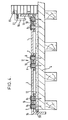
- FIG. 1 a prospective view of part of a roof according to the present invention is shown.
- Two panels 1 are fixed to a strip 2 which overlaps the edge regions 3 of the panels 1.
- the strip 2 is disposed above a sub-structure 4 of a building to which the roof is applied.
- the panels 1 are provided in their edge regions 3 with apertures 5 which align with apertures 6 in the strip 2.
- a fixing means 8 for example a screw.
- the upper end of the screw is provided with a washer 9 which overlaps the panel around the aperture 5 to support the fixing means which holds the panels 1 to the strip 2 and subsequently to the sub-structure 4 of the building.
- An intermediate layer 10 is provided in the space between each panel 1 and between the edge regions 3 of the panels 1 and the strip 2.
- the intermediate layer 10 of a resilient material permits the panels 1 to flex relative to each other and relative to the strip 2.
- An entire roof may be constructed from an array of such panels 1 and, if this is desired, the roof is constructed by initially laying down an arrangement of strips as shown in Figure 2.
- the bold lines show the strips 2 and the dotted lines show the position of panels (not shown) positioned over the strips 2.
- the apertures 6 in the strip are shown. In preferred embodiments, these apertures will be at approximately 2ft. (600mm) intervals.
- the panel (not shown) will not abut other panels.
- the panels (not shown) are secured resiliently to the strip 2 defining the periphery of the arrangement of strips and that peripheral strip is secured to the sub-structure of a building.
- the section of a roof comprises panels 1 which are secured together at the position indicated by reference numeral 11 in a manner similar to that shown in Figure 2.
- this embodiment of the present invention additionally comprises an insulating layer 12 through which the fixing means 8 must pass before being secured to the sub-structure 4 of the building.
- the insulating layer is preferably of a closed cell foam material.
- the roof is secured in a manner similar to that shown in Figure 2.
- the overhanging detail 14 may be considered as a panel, the overhanging portion 14 being secured to the adjacent panel 1 as shown in Figure 2.
- the arrangement shown for securing the roof to the wall 13 comprises an L-shaped section which is adjacent a panel, the L-shaped section 15 being resiliently secured to the adjacent panel 1 in a manner as shown in Figure 2.
- the overhanging flashing 16 protects the L-shaped portion 15 whilst allowing air to enter freely the space between the insulating layer 12 and the panels 1.
- Treated battens 30 and 31 serve to support the sections 14 and 16 respectively.
- the gap between the panel and the insulating layer is equal to the height of the strip and is preferably about 2mm.
- the sub-structure or decking 4 may be covered with a membrane which seals the decking or sub-structure 4.
- FIG 5 a closer detail of the means by which two adjacent panels are fixed together is shown.
- the edge regions of three of the panels overlap the strip 2 which, in a "cold roof” application, is positioned above the decking ,4 of a building which is being roofed.
- the apertures 5 and 6 define a passage in which a sleeve 17 sits.
- the outside diameter of the sleeve 17 is less than the internal diameter of the apertures 5, 6.
- a washer 18 overlies the aperture 5 and supports the head 19 of the fixing means, for example a screw 20.
- the outer diameter of the fixing means 20 is less than the inner diameter of the sleeve 17.
- the spaces between the panels 3 and the strip 2 and the spaces in the apertures are filled with the resilient sealing material 10 which is preferably a rubber sealing material, for example that sealing material known by the Registered Trade Mark SIKAFLEX.
- the strip When the joint is constructed, the strip is laid down, and preferably tacked, to the decking of the building to be roofed. A layer of the liquid resilient sealing material is applied over the strip and the panel is then positioned above the strip 2 such that pre-drilled apertures 5, 6 overlap.
- the sleeve 17 is placed through the apertures 5, 6 and the fixing means 20 is passed through the sleeve, through the layer of insulating material 12 and into the decking 4.
- the action of screwing the panel to the strip squeezes the liquid resilient sealing material 10 into all the empty spaces around the sleeve and fixing means. Further liquid resilient sealing material may be applied over the head of the fixing means once the panel 3 and strip 2 have been screwed down.
- FIGs 6 to 9 show how the roof of the present invention may be adapted to cooperate with existing features of a roof.
- the roof cooperates with a sky light 21.
- the panels are pre-formed such that when positioned during construction the panels abut the sky light.
- Under the panels 3 is laid a strip 2 to which the panel 3 is secured in a manner as described with reference to Figure 2.
- Resilient sealing material is provided around the sky light to seal the skylight.
- the panels 3 have upturns 33 which lie below overlapping portions 34 of the skylight, there being a passage therebetween for the movement of air.
- a valley gutter 22 is secured in position as if it were a panel as described above.
- the overhanging drip off flashing 23 can also be considered as another panel which is fixed to the valley guttering in a manner as described above.
- a flue 24 is accommodated in the roof.
- a draingage portion 27 is sealed into the roof in a manner as described hereinbefore, the draingage portion 27 having lips 28 which drain into an existing drain of the building.
- the drain is thus an integral drain of the roof.
- a flat roof 101 is provided with a panel of fibreglass material 102.
- the panel of fibreglass 102 lies above an insulating layer 103.
- the insulating layer 103 comprises a plurality of spaced apart insulating boards.
- the insulating boards 103 which are supported on a sub-structure (not shown) may be spaced at 6mm intervals.
- the panel of fibreglass 102 is constructed to cooperate with existing features of the roof.
- an existing flashing 104 of the roof cooperates with a rim 105 of the panel.
- a small gap may be left between the flashing 104 and the rim 105 to allow air to pass into the space between the panel 102 and the insulating layer 103.
- the panel 102 expands in hot weather, the panel 102 forms a dome, with air being sucked in through the gap between the flashing 104 and the rim 105.
- the flow of air acts to prevent any build up of condensation or moisture in the space between the panel 102 and the sub-structure (not shown).
- a, rim 106 is provided around the periphery of the panel 102; this rim 106 has a downwardly extending portion 107 which may be secured to the sub-structure (not shown).
- the sub-structure 108 is shown.
- the insulating boards 103 rest upon the sub-structure 108 and the panel of fibreglass 102 is, in this embodiment, slightly spaced from the insulating board leaving an air passage 109.
- Into the panel 102 there is cast a steel plate 110.
- the steel plate 110 is secured to the sub-structure by means of a rubber restraint 111 which permits but generally counters any uplift, due to expansion, of the panel of fibreglass 102.
- Figure 12 shows the rubber restraint 111 in more detail.
- the steel plate 110 has, welded therein, an eye 112.
- the sub-structure 108 has a ring bolt 113 which is bolted through the sub-structure in this embodiment but which, in another embodiment, may be screwed into the sub-structure.
- the rubber restraint 111 which acts as a "shock cord" connects the steel plate and the sub-structure.
- a large roof which is constructed from a number of fibreglass sheets joined together can be envisaged.
- several restraining means as illustrated in Figures 11 and 12 may be provided at spaced apart intervals inward of the periphery of the panel of fibreglass material. This allows the expansion to be spread over the entire panel of fibreglass material so that, rather than the whole panel forming a single large dome, the whole panel rises by a small, less significant, amount.
Landscapes
- Engineering & Computer Science (AREA)
- Architecture (AREA)
- Civil Engineering (AREA)
- Structural Engineering (AREA)
- Mechanical Engineering (AREA)
- Roof Covering Using Slabs Or Stiff Sheets (AREA)
- Building Environments (AREA)
Applications Claiming Priority (4)
| Application Number | Priority Date | Filing Date | Title |
|---|---|---|---|
| GB8429194 | 1984-11-19 | ||
| GB08429194A GB2167100A (en) | 1984-11-19 | 1984-11-19 | Roof |
| GB08520339A GB2168092B (en) | 1984-11-19 | 1985-08-14 | A roof and a method of providing a building with a roof |
| GB8520339 | 1985-08-14 |
Publications (2)
| Publication Number | Publication Date |
|---|---|
| EP0183459A2 true EP0183459A2 (de) | 1986-06-04 |
| EP0183459A3 EP0183459A3 (de) | 1988-05-18 |
Family
ID=26288473
Family Applications (1)
| Application Number | Title | Priority Date | Filing Date |
|---|---|---|---|
| EP85308370A Withdrawn EP0183459A3 (de) | 1984-11-19 | 1985-11-18 | Dach und Methode, ein Gebäude mit einem Dach zu versehen |
Country Status (2)
| Country | Link |
|---|---|
| US (1) | US4711061A (de) |
| EP (1) | EP0183459A3 (de) |
Cited By (1)
| Publication number | Priority date | Publication date | Assignee | Title |
|---|---|---|---|---|
| CN106640877A (zh) * | 2016-12-31 | 2017-05-10 | 重庆安特管业有限公司 | 一种污水处理箱连接结构 |
Families Citing this family (7)
| Publication number | Priority date | Publication date | Assignee | Title |
|---|---|---|---|---|
| US20030177708A1 (en) * | 2002-03-20 | 2003-09-25 | Gatherum Roy Dean | Flashing for foundation/exterior treatment interface |
| US20120225236A1 (en) * | 2011-03-03 | 2012-09-06 | James Edward Cox | Composite Building Panel and Method |
| CN102330473A (zh) * | 2011-07-14 | 2012-01-25 | 大连美宸特科技有限公司 | 一种带有涂层的山墙封口结构 |
| EP2584133B1 (de) * | 2011-10-19 | 2014-03-19 | ISO-Chemie GmbH | Verfahren zur Abdichtung bei der Fenstersanierung |
| US8875455B1 (en) * | 2014-05-28 | 2014-11-04 | Zep Solar, Llc | Ramp mounting system for a flat roof solar array |
| US10934706B2 (en) * | 2017-03-30 | 2021-03-02 | Alan Stein | System and method for attaching glass panels to a substructure |
| SE2330386A1 (en) * | 2022-09-12 | 2024-03-13 | Reidar Hagner | Self-Sealing Mounting and Fastening Element |
Family Cites Families (13)
| Publication number | Priority date | Publication date | Assignee | Title |
|---|---|---|---|---|
| US2068098A (en) * | 1936-02-24 | 1937-01-19 | Elmendorf Armin | Fastening panels that shrink |
| US2150217A (en) * | 1938-03-12 | 1939-03-14 | Gettelman Fredrick | Roof |
| US2306537A (en) * | 1941-10-07 | 1942-12-29 | Albert M Hamm | Trailer canopy |
| US3121977A (en) * | 1956-02-08 | 1964-02-25 | Bersudsky Sidney | Building panel structure |
| US2923305A (en) * | 1957-08-07 | 1960-02-02 | Firestone Tire & Rubber Co | Sealing closure |
| CA935619A (en) * | 1969-07-10 | 1973-10-23 | Comalco Limited | Secret fix roofing |
| CH637724A5 (de) * | 1979-06-05 | 1983-08-15 | Idc Chemie Ag | Isolierte aussenbekleidung fuer gebaeudewaende. |
| GB2061350A (en) * | 1979-08-29 | 1981-05-13 | Booth Muirie Ltd | Seal and cladding system |
| NO793519L (no) * | 1979-11-01 | 1981-05-05 | Protan & Fagertun As | Fremgangsmaate ved festing av isolerende og tettende sjikt samt anordning for utfoerelse av fremgangsmaaten |
| US4320605A (en) * | 1979-11-14 | 1982-03-23 | Scientific Applications Incorporated | Insulation panel |
| DE3214890A1 (de) * | 1982-04-22 | 1983-11-03 | Anton Grimm GmbH, 6951 Limbach | Dachauflage |
| US4519175A (en) * | 1983-06-15 | 1985-05-28 | Carlisle Corporation | Lubricated roofing membrane fastener |
| CA1247409A (en) * | 1984-01-09 | 1988-12-28 | George D. Hewison | Fastening assembly |
-
1985
- 1985-11-18 EP EP85308370A patent/EP0183459A3/de not_active Withdrawn
- 1985-11-19 US US06/799,431 patent/US4711061A/en not_active Expired - Fee Related
Cited By (1)
| Publication number | Priority date | Publication date | Assignee | Title |
|---|---|---|---|---|
| CN106640877A (zh) * | 2016-12-31 | 2017-05-10 | 重庆安特管业有限公司 | 一种污水处理箱连接结构 |
Also Published As
| Publication number | Publication date |
|---|---|
| US4711061A (en) | 1987-12-08 |
| EP0183459A3 (de) | 1988-05-18 |
Similar Documents
| Publication | Publication Date | Title |
|---|---|---|
| US10577803B2 (en) | Supporting a load on a roof | |
| CA2749162C (en) | Support for roof penetrating structures | |
| US5323576A (en) | Metal roofing skylight | |
| US4860511A (en) | Standing seam roof skylight systems | |
| US6233889B1 (en) | Ventilated roof membrane plate and method of installing membrane roof utilizing same | |
| US6401412B1 (en) | Metal roof system | |
| US20040226247A1 (en) | Building panel with impermeable surface layer | |
| US5408797A (en) | Mid-roof anchoring system | |
| US8713864B1 (en) | Skylight for metal panel roof | |
| US9322176B2 (en) | Sustainable energy efficient roof system | |
| US7658052B2 (en) | Roof structure and method for making the same | |
| US11697940B2 (en) | Enhanced roofing system | |
| US6079167A (en) | Continuous ridge skylight system | |
| US4548006A (en) | Self-flashing channeled skylight | |
| US4711061A (en) | Roof and a method of providing a building with a roof | |
| US4706432A (en) | Air vapor securement closure for a membrane roofing system | |
| US6272807B1 (en) | Rain directional panel | |
| GB2142947A (en) | Ventilated roof abutment curb | |
| GB2168092A (en) | Roof | |
| JPH10306519A (ja) | 断熱屋根及び断熱壁 | |
| JPS63578B2 (de) | ||
| WO2024225890A1 (en) | Waterproof roof system | |
| GB2231892A (en) | Building roofs | |
| JPH0712521Y2 (ja) | 屋根の換気構造 | |
| Piteo et al. | How to Vent—Details of Steep Slope Vented Roof Design with Structural Insulated Panels |
Legal Events
| Date | Code | Title | Description |
|---|---|---|---|
| PUAI | Public reference made under article 153(3) epc to a published international application that has entered the european phase |
Free format text: ORIGINAL CODE: 0009012 |
|
| AK | Designated contracting states |
Kind code of ref document: A2 Designated state(s): AT BE CH DE FR GB IT LI LU NL SE |
|
| PUAL | Search report despatched |
Free format text: ORIGINAL CODE: 0009013 |
|
| AK | Designated contracting states |
Kind code of ref document: A3 Designated state(s): AT BE CH DE FR GB IT LI LU NL SE |
|
| 17P | Request for examination filed |
Effective date: 19880811 |
|
| 17Q | First examination report despatched |
Effective date: 19890913 |
|
| STAA | Information on the status of an ep patent application or granted ep patent |
Free format text: STATUS: THE APPLICATION IS DEEMED TO BE WITHDRAWN |
|
| 18D | Application deemed to be withdrawn |
Effective date: 19911112 |
|
| RIN1 | Information on inventor provided before grant (corrected) |
Inventor name: WILKINSON, JOHN Inventor name: HOLBROOK, NICHOLAS |