EP0183468B1 - Appareil pour cuire et réfrigérer des produits alimentaires utilisant un échangeur de chaleur pour traiter des effluents aqueux - Google Patents
Appareil pour cuire et réfrigérer des produits alimentaires utilisant un échangeur de chaleur pour traiter des effluents aqueux Download PDFInfo
- Publication number
- EP0183468B1 EP0183468B1 EP85308402A EP85308402A EP0183468B1 EP 0183468 B1 EP0183468 B1 EP 0183468B1 EP 85308402 A EP85308402 A EP 85308402A EP 85308402 A EP85308402 A EP 85308402A EP 0183468 B1 EP0183468 B1 EP 0183468B1
- Authority
- EP
- European Patent Office
- Prior art keywords
- tank
- casings
- thermal
- heat exchanger
- body member
- Prior art date
- Legal status (The legal status is an assumption and is not a legal conclusion. Google has not performed a legal analysis and makes no representation as to the accuracy of the status listed.)
- Expired - Lifetime
Links
- 235000013305 food Nutrition 0.000 title claims description 72
- 238000010411 cooking Methods 0.000 title claims description 59
- XLYOFNOQVPJJNP-UHFFFAOYSA-N water Substances O XLYOFNOQVPJJNP-UHFFFAOYSA-N 0.000 title description 102
- 238000000034 method Methods 0.000 title description 69
- 230000008569 process Effects 0.000 title description 69
- 239000000463 material Substances 0.000 claims description 20
- 230000033001 locomotion Effects 0.000 claims description 16
- 239000012530 fluid Substances 0.000 claims description 15
- 238000012545 processing Methods 0.000 claims description 12
- 238000011049 filling Methods 0.000 claims description 7
- 230000008878 coupling Effects 0.000 claims description 3
- 238000010168 coupling process Methods 0.000 claims description 3
- 238000005859 coupling reaction Methods 0.000 claims description 3
- 230000000694 effects Effects 0.000 claims description 3
- 238000004891 communication Methods 0.000 claims description 2
- 238000005728 strengthening Methods 0.000 claims description 2
- 239000007788 liquid Substances 0.000 description 19
- 230000003068 static effect Effects 0.000 description 15
- 238000001816 cooling Methods 0.000 description 12
- 238000003860 storage Methods 0.000 description 11
- 230000009471 action Effects 0.000 description 10
- 238000010438 heat treatment Methods 0.000 description 7
- 230000008901 benefit Effects 0.000 description 6
- 235000012054 meals Nutrition 0.000 description 6
- 229910052751 metal Inorganic materials 0.000 description 6
- 239000002184 metal Substances 0.000 description 5
- 235000012206 bottled water Nutrition 0.000 description 4
- 239000003651 drinking water Substances 0.000 description 4
- 238000009434 installation Methods 0.000 description 4
- 238000004519 manufacturing process Methods 0.000 description 4
- 230000013011 mating Effects 0.000 description 4
- 230000007246 mechanism Effects 0.000 description 4
- DNIAPMSPPWPWGF-UHFFFAOYSA-N Propylene glycol Chemical compound CC(O)CO DNIAPMSPPWPWGF-UHFFFAOYSA-N 0.000 description 3
- 235000015278 beef Nutrition 0.000 description 3
- 238000013461 design Methods 0.000 description 3
- 239000000796 flavoring agent Substances 0.000 description 3
- 235000019634 flavors Nutrition 0.000 description 3
- 238000009428 plumbing Methods 0.000 description 3
- 239000000523 sample Substances 0.000 description 3
- 238000007789 sealing Methods 0.000 description 3
- 241000894006 Bacteria Species 0.000 description 2
- RYGMFSIKBFXOCR-UHFFFAOYSA-N Copper Chemical compound [Cu] RYGMFSIKBFXOCR-UHFFFAOYSA-N 0.000 description 2
- 240000007594 Oryza sativa Species 0.000 description 2
- 235000007164 Oryza sativa Nutrition 0.000 description 2
- 239000004809 Teflon Substances 0.000 description 2
- 229920006362 Teflon® Polymers 0.000 description 2
- 230000001580 bacterial effect Effects 0.000 description 2
- 239000000498 cooling water Substances 0.000 description 2
- 229910052802 copper Inorganic materials 0.000 description 2
- 239000010949 copper Substances 0.000 description 2
- 238000007710 freezing Methods 0.000 description 2
- 230000008014 freezing Effects 0.000 description 2
- 239000004615 ingredient Substances 0.000 description 2
- 239000000203 mixture Substances 0.000 description 2
- 230000004048 modification Effects 0.000 description 2
- 238000012986 modification Methods 0.000 description 2
- 235000019629 palatability Nutrition 0.000 description 2
- 238000002360 preparation method Methods 0.000 description 2
- 230000003134 recirculating effect Effects 0.000 description 2
- 230000009467 reduction Effects 0.000 description 2
- 238000005057 refrigeration Methods 0.000 description 2
- 238000003303 reheating Methods 0.000 description 2
- 235000009566 rice Nutrition 0.000 description 2
- 239000007787 solid Substances 0.000 description 2
- 239000003351 stiffener Substances 0.000 description 2
- 235000019587 texture Nutrition 0.000 description 2
- 229910001369 Brass Inorganic materials 0.000 description 1
- 229910000906 Bronze Inorganic materials 0.000 description 1
- 240000004160 Capsicum annuum Species 0.000 description 1
- 235000008534 Capsicum annuum var annuum Nutrition 0.000 description 1
- 229910001006 Constantan Inorganic materials 0.000 description 1
- 239000004278 EU approved seasoning Substances 0.000 description 1
- 241000287828 Gallus gallus Species 0.000 description 1
- 244000061456 Solanum tuberosum Species 0.000 description 1
- 235000002595 Solanum tuberosum Nutrition 0.000 description 1
- 206010044625 Trichorrhexis Diseases 0.000 description 1
- 230000003416 augmentation Effects 0.000 description 1
- 230000003190 augmentative effect Effects 0.000 description 1
- 230000015572 biosynthetic process Effects 0.000 description 1
- 239000010951 brass Substances 0.000 description 1
- 239000010974 bronze Substances 0.000 description 1
- 235000013351 cheese Nutrition 0.000 description 1
- 230000000295 complement effect Effects 0.000 description 1
- 238000009833 condensation Methods 0.000 description 1
- 230000005494 condensation Effects 0.000 description 1
- 239000000470 constituent Substances 0.000 description 1
- 238000011109 contamination Methods 0.000 description 1
- 230000008602 contraction Effects 0.000 description 1
- 239000002826 coolant Substances 0.000 description 1
- KUNSUQLRTQLHQQ-UHFFFAOYSA-N copper tin Chemical compound [Cu].[Sn] KUNSUQLRTQLHQQ-UHFFFAOYSA-N 0.000 description 1
- 230000007547 defect Effects 0.000 description 1
- 230000006866 deterioration Effects 0.000 description 1
- 235000013601 eggs Nutrition 0.000 description 1
- 238000004049 embossing Methods 0.000 description 1
- -1 ferrous metals Chemical class 0.000 description 1
- 235000011194 food seasoning agent Nutrition 0.000 description 1
- 230000008570 general process Effects 0.000 description 1
- 235000021268 hot food Nutrition 0.000 description 1
- 230000001939 inductive effect Effects 0.000 description 1
- 238000011068 loading method Methods 0.000 description 1
- 238000012423 maintenance Methods 0.000 description 1
- 235000015255 meat loaf Nutrition 0.000 description 1
- 239000000155 melt Substances 0.000 description 1
- 238000002156 mixing Methods 0.000 description 1
- 238000012261 overproduction Methods 0.000 description 1
- 238000004806 packaging method and process Methods 0.000 description 1
- 230000002093 peripheral effect Effects 0.000 description 1
- 229920000515 polycarbonate Polymers 0.000 description 1
- 239000004417 polycarbonate Substances 0.000 description 1
- 235000015277 pork Nutrition 0.000 description 1
- 235000012015 potatoes Nutrition 0.000 description 1
- 244000144977 poultry Species 0.000 description 1
- 238000010926 purge Methods 0.000 description 1
- 235000020989 red meat Nutrition 0.000 description 1
- 238000009877 rendering Methods 0.000 description 1
- 238000012163 sequencing technique Methods 0.000 description 1
- 238000007493 shaping process Methods 0.000 description 1
- 239000002002 slurry Substances 0.000 description 1
- 229910001220 stainless steel Inorganic materials 0.000 description 1
- 239000010935 stainless steel Substances 0.000 description 1
- 239000008399 tap water Substances 0.000 description 1
- 235000020679 tap water Nutrition 0.000 description 1
- 238000012546 transfer Methods 0.000 description 1
- 239000002699 waste material Substances 0.000 description 1
Images


Classifications
-
- A—HUMAN NECESSITIES
- A23—FOODS OR FOODSTUFFS; TREATMENT THEREOF, NOT COVERED BY OTHER CLASSES
- A23B—PRESERVATION OF FOODS, FOODSTUFFS OR NON-ALCOHOLIC BEVERAGES; CHEMICAL RIPENING OF FRUIT OR VEGETABLES
- A23B2/00—Preservation of foods or foodstuffs, in general
- A23B2/30—Preservation of foods or foodstuffs, in general by heating materials in packages which are not progressively transported through the apparatus
- A23B2/37—Preservation of foods or foodstuffs, in general by heating materials in packages which are not progressively transported through the apparatus with packages moving on the spot
-
- A—HUMAN NECESSITIES
- A23—FOODS OR FOODSTUFFS; TREATMENT THEREOF, NOT COVERED BY OTHER CLASSES
- A23B—PRESERVATION OF FOODS, FOODSTUFFS OR NON-ALCOHOLIC BEVERAGES; CHEMICAL RIPENING OF FRUIT OR VEGETABLES
- A23B2/00—Preservation of foods or foodstuffs, in general
- A23B2/003—Control or safety devices for sterilisation or pasteurisation systems
-
- A—HUMAN NECESSITIES
- A23—FOODS OR FOODSTUFFS; TREATMENT THEREOF, NOT COVERED BY OTHER CLASSES
- A23B—PRESERVATION OF FOODS, FOODSTUFFS OR NON-ALCOHOLIC BEVERAGES; CHEMICAL RIPENING OF FRUIT OR VEGETABLES
- A23B2/00—Preservation of foods or foodstuffs, in general
- A23B2/20—Preservation of foods or foodstuffs, in general by heating materials in packages which are progressively transported, continuously or stepwise, through the apparatus
- A23B2/205—Preservation of foods or foodstuffs, in general by heating materials in packages which are progressively transported, continuously or stepwise, through the apparatus with packages on a drum with horizontal axis
Definitions
- the invention concerns an apparatus for thermal processing of food materials sealed in flexible casings.
- the CRYOVAC® Process involves the packaging at appropriate temperatures of foods which are packaged in one of several types of casings such as are produced by W. R. Grace Company and particularly the CRYOVAC Division, these casings being designated as C-300 and L-600 casings for example.
- Food items cooked in kettles and pumped into such casings or actually cooked within such casings are rapidly cooled to a temperature of approximately 4 °C within a relatively short period of time, for example 30 to 40 minutes, and then stored at temperatures between -2 ° to 0 °C for periods of time of up to approximately 45 days. Refrigerated storage is possible for this period of time without freezing due to the low bacteria count in the sealed casings.
- Food prepared in this manner retains the flavor, texture and palatability of freshly cooked foods once the food is rethermalized to serving temperature.
- Apparatus previously employed for practice of the CRYOVAC® Process has been designed and intended for large scale cooking operations, that is, greater than 2500 meals per day, no prior apparatus being available to small volume users.
- an apparatus for thermal processing of food materials sealed in flexible casings which comprises: tank means for holding a thermal medium in which the sealed flexible casings are substantially immersed and thermally processed, means communicating with the tank means for filling the tank means with said thermal medium; a hollow body member mountable for motion within the tank means and receiving the flexible casings therewithin for imparting motion to said casings therewithin for imparting motion to said casings to facilitate thermal processing of the food material sealed within the casings; apertures formed in at least a portion of the walls of said hollow body member, the apertures facilitating flow of the thermal medium through the body member on movement of the body member; means mounting the hollow body member within the tank means for moving the hollow body member; said communication means being adapted for selectively filling the tank with said thermal medium at a temperature suitable for either cooking or chilling food materials within the flexible casings, the thermal processing occurring within the same tank means without removal of the sealed flexible casings from the tank means between cooking and chilling steps; heat exchange means coupled to at least one
- the apparatus of the invention is capable of cooking and chilling food items sealed in casings for subsequent refrigerated storage over extended periods of time and particularly capable of both sequentially cooking and chilling food items within a single tank structure.
- the apparatus has the capability of tumble chilling cooked food items in casings to rapidly cool the contents of the casings from a cooking temperature at which bacteria are effectively killed to a relatively cool temperature at which bacterial action is reduced to allow refrigerated storage for substantial periods of time without loss of flavor, texture and palatability.
- the apparatus of the invention is cost effective and energy efficient by supplying both heated and chilled potable process water to a tank within which such cooking and chilling occurs.
- the apparatus of the invention has the capability of practicing the CRYOVAC® Process in small volume, typically less than 2500 meals per day, over a monthly production schedule.
- the present invention particularly replaces multiple pieces of equipment within the known larger system described hereinbefore and provides capabilities within a single apparatus which has not heretofor been available.
- the present apparatus efficiently provides within a relatively inexpensive structure the capability of both cooking and chilling food items sealed within casings such as are described in U.S. patent 4,218,486 and also provides the capability of tumble chilling, tumble cooking and tumble rethermalization with a desired massaging action of casings filled with food items and materials cooked in either the present apparatus or other apparatus.
- the present apparatus therefore contributes to an efficient practice, particularly on a relatively small scale, of the CRYOVAC® Process while contributing to the provision of an overall system which is inexpensive and compact.
- the present apparatus may include a tumble chiller cylinder which is perforated to allow free flow of a liquid chilling medium and which is provided with longitudinally spaced "ribs" which act to strengthen the cylinder and also act to deform the casing on contact to thereby cause movement of the food materials contained within the casings such that uniform chilling of the contents of the casings is accomplished.
- the present apparatus also provides the capability of tumble cooking of food sealed within casings. Food such as instant potatoes, powdered eggs and the like, can be charged in the casings with appropriate seasonings and other ingredients and sealed.
- the sealed casings are then placed within the present apparatus and particularly within the confines of the tumble cylinder with water at a cooking temperature being charged into the apparatus on closure thereof, tumbling of the cylinder acting to massage the contents of the casings and thereby admix said contents while cooking same to a desired temperature.
- the food products thus cooked may be served at once while hot or chilled for storage and future use.
- the apparatus is then drained, preferably automatically, of the cooking water and filled with chilled water followed by tumble chilling according to a preferred mode of use of the apparatus so as to cool the contents of the casings to a desired temperature within a desired period of time to allow storage of the thus-cooked and chilled food materials according to the process referred to hereinabove.
- Refrigerated food items in sealed casings can also be rethermalized to serving temperatures prior to serving by subjection to tumble heating within the present apparatus.
- the massaging action previously described relative to tumble chilling and tumble cooking acts in substantially the same manner to heat the cool foods within the sealed casings to a desired serving temperature.
- a heated water bath within the apparatus is thereby more efficiently employed for reheating of the previously cooked and stored foods.
- Rethermalization can thus be accomplished due in part to the massaging action within approximately the same period of time, that is, 45 to 60 minutes, as is required to cool the hot food items in sealed casings as noted above.
- the time period for reheating the cooled food items from storage is not, however, critical.
- the apparatus essentially comprises a tank having an upper portion which opens to allow access to the interior of the tank, the tank being generally cylindrical but with modification from this general conformation.
- the tank has its longitudinal axis disposed substantially horizontally and is mounted upon appropriate leg mounts or the like.
- a steam jacket formed on lower exterior walls of the tank allows heating of the liquid media within the tank so that cooking within the tank can be accomplished.
- Steam connections to the steam jacket are provided in a conventional manner with water outlet and inlet connections to the interior of the tank being also provided and controlled by appropriate control mechanisms.
- the steam-jacketed tank so provided can be used with appropriate mounting baskets to hold food materials such as beef roast and the like in appropriate casings, the tank being charged with hot water for slow water cooking in a static mode. Upon completion of such a cooking cycle, the hot cooking water is drained and the tank is charged with chilled water which rapidly cools the cooked food within the casings to a desired temperature within a desired period of time for storage under refrigeration.
- steam or other heated fluid is supplied to a heat exchange device, preferably a shell and tube heat exchanger, to heat potable process water which is circulated through the heat exchange device from a tank in which cooking of food materials within sealed casings occurs.
- a heat exchange device preferably a shell and tube heat exchanger
- the heated cooking water is preferably dumped and potable process water is chilled within the same heat exchange device by means of a cold liquid passing in heat exchange relation with the potable process water within the same exchanger used for heating of the process water during the cooking cycle.
- the potable process water is circulated, preferably continuously, through the heat exchanger and in heat exchange relation with the chilled liquid in order to maintain a desired cooling rate within the tank.
- the cooked contents within the casings are preferably chilled to a desired temperature, on the order of 4 °C, within a desired period of time, this period of time ranging between 30 and 45 minutes for maximum shelf life and preferably not greater than 60 minutes.
- This rapid chilling reduces bacterial growth and rapidly quenches the cooking process to assist in the maintenance of the freshness and eating quality of the food product contained within the casings.
- the the shape of the tank is not critical, thereby rendering a system configured according to the invention less expensive from the standpoint of equipment costs as well as the labor costs required for manufacture of the apparatus. Further, an energy efficient cooking system is provided since a complete cooking apparatus configured according to the present invention does not radiate substantial heat from the cooking tank even if the cooking tank is not insulated.
- a system configured according to the invention can be better insulated for even greater energy efficiency. Operational advantages accrue from the ability to rapidly heat the potable process water. Design flexibility is also created within a total cooking system since system size can be readily varied by variations of the capacities of pumps and heat exchange devices.
- the heat exchange portion of the present embodiment can be compactly packaged and placed remotely from the cooking tank in order to maximize design requirements for particular installations.
- the apparatus includes a tumble cylinder which is perforated and which is mounted for rapid assembly and disassembly within the tank with the longitudinal axis of the tumble cylinder being disposed in a substantially horizontal orientation.
- the cylinder is mounted on quick-disconnect drive and butt shafts such that the tumble cylinder can be rotated in any of a number of desired modes of rotation, either partial or complete, in order to tumble casings filled with food materials within the interior of the cylinder, thereby to either cook or chill food placed within the casings.
- the tumbling action of the cylinder coupled with a massaging action provided by the tumbling and augmented by rib structures which extend into the interior of the cylinder causes the contents of the casings to be efficiently and uniformly mixed and either heated or chilled as desired, the structure being useful in the chilling of food materials within casings to a desired low temperature within relatively short periods of time in order to accommodate the requirements of the CRYOVAC Process as described in United States patent 4,218,486.
- the level of both cooking and cooling water within the tank can be readily adjusted from externally of the tank and the motion of the tumble cylinder can be controlled over any desired degree of partial or complete revolution and multiples thereof in any desired sequence.
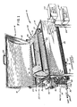
- a first embodiment of the present apparatus is seen at 10 to comprise a tank 12 having a tank cover 14 hinged along opposing edges as will be described hereinafter, the tank 12 having a lower portion which describes a minor portion of a cylinder and having front and rear straight walls 13 and 15, the longitudinal axis of the tank 12 being disposed substantially horizontally.
- the rear straight wall 15 of the tank 12 extends at an angle to the vertical and is flared rearwardly to allow clearance when the tank cover 14 is in the open position. Further, the configuration of the rear wall 15 facilitates opening of the upper portion of a tumble cylinder 50 which will be described hereinafter.
- the tank 12 also includes a steam lip 16 which takes the form of a flange-like element extending about the full perimeter of the opening of the tank 12, the steam lip 16 mating with steam lip 18 on the tank cover 14 to function in the manner of a seal to maintain both water and heated vapors within the interior of the tank 12 when the tank cover 14 is closed thereover.
- a steam lip 16 which takes the form of a flange-like element extending about the full perimeter of the opening of the tank 12, the steam lip 16 mating with steam lip 18 on the tank cover 14 to function in the manner of a seal to maintain both water and heated vapors within the interior of the tank 12 when the tank cover 14 is closed thereover.
- the tank cover 14 can be opened and closed through the use of handle 20, the tank cover 14 being controlled in closing movement relative to the tank 12 by means of either a pneumatic cylinder and rod mechanism 22 or tension springs (not shown) which are mounted to the tank 12 and the tank cover 14 in order to provide a slow closing of the tank cover 14.
- a drip lip 24 extends downwardly along the center periphery of the tank cover 14 to accommodate drainage of moisture which condenses on the inside of the tank cover 14, the drip lip 24 directing the mixture into the interior of the tank 12 in order to prevent spillage of liquid externally of the apparatus 10.
- the tank 12 is provided with a steam jacket 26 which can be formed in a variety of ways depending upon preference.
- An inexpensive and effective manner of providing the steam jacket 26 is through embossing.
- the steam jacket 26 provides a space over lower portions of the tank 12 into which steam can be directed in order to heat a liquid such as water which is contained within the tank 12, thereby to cook foods sealed in casings 11 which are contained within the apparatus 10.
- Steam provided to fill the steam jacket 26 enters said jacket through steam inlet 25 and exists through a steam outlet (not shown), condensation exiting the steam jacket through a drain 27. All of these elements are essentially conventional.
- the casings 11 such as are seen in Figure 2 are held within baskets 13 and the food items within the casings 11, such as whole roasts, chicken parts, and the like, are cooked and cooled in a static mode.
- shelves (not shown) can be substituted for the baskets 13 in order to separate the casings 11 and allow thorough cooking and cooling.
- the tank 12, both with and without the baskets 13, can be used without tumble cylinder 50 as a matter of convenience when using the static processing mode.
- casings 11 filled with food items are placed in the tumble cylinder 50 without the use of the baskets 13 or other structure in order to cook, chill or rethermalize the food items within the casings. In these processing modes, the tumbler cylinder 50 is rotated to provide the advantages herein described.
- the tank 12 is mounted to legs 28 in order to maintain the apparatus 10 in a substantially horizontal disposition, the tank 12 being elevated above floor level in order to accommodate a drain 30 which drains water as required from the tank 12 at completions of a cooking or cooling cycle.
- a cold water inlet 32 is provided at one end of the tank 12 for filling the tank with tap water from a supply 101 to a desired level.
- the drain 30 is disposed at an opposite end of the tank 12 so that a uniform end-to-end circulation of water can be effected, thereby providing more uniform temperature.
- a water outlet (not shown) separate from the drain 30 is provided for recirculation of water in association with a water recirculation inlet 33.
- the drain 30 can alternatively be used for removal of water from the tank 12 in a recirculating arrangement.
- the water level within the tank 12 is selected through operation of the water level adjustment mechanism 34.
- a polycarbonate impact resistant sight tube 36 mounted to communicate with the interior of the tank 12 is disposed vertically on one side of the tank 12.
- a manual shutoff valve 38 is mounted appropriately on the tube 36 for the purpose of discontinuing the flow of water into the tube 36.
- the water level within the tank 12 can thus be determined from simple observation of the tube 36.
- a pair of proximity switches 40 are mounted at desired levels along the tube 36 in order that a desired high and low water level within the tank 12 can be selected and maintained.
- the proximity switches 40 are of a capacitive type such as is manufactured by Automatic Timer and Control Company of King of Prussia, Pennsylvania, the upper switch 40 sensing the water level within the tube 36 and being electronically connected to appropriate controls to discontinue filling of the tank 12 through the water inlet 32 when the water level within the tube 36 reaches the level at which the upper proximity switch 40 is disposed.
- the proximity switches 40 are mounted on bars 42 which are connected to sleeves 44, the sleeves 44 being free to travel along a vertical rod 46 mounted to the side of the tank 12 next to and parallel with the tube 36, manually operated knobs 48 actuating a set screw (not shown) to hold the sleeves 44 and thus the switches 40 at a desired vertical orientation along the rod 46 and relative to the tube 36.
- the lower proximity switch 40 is used to start the process of filling the tank 12 and to control a recirculating water pump (not shown) which is used in both cooking and chilling cycles. Temperature control of the water within the tank 12 is maintained by an insert probe temperature sensor shown at 19 and which is connected to appropriate controls (not shown) in a conventional manner.
- FIGS 1 and 2 show a tumble cylinder 50 mounted within the tank 12 by means of a quick-disconnect drive shaft arrangement similar to that described in United States patent application, Serial No. 468,764, filed February 22, 1983, and assigned to the present assignee, the drive shaft arrangement of said patent application being used with the shaft of a rotary agitator.
- the tumble cylinder 50 mounts to the tank 12 at an "active" end by means of a stub shaft arrangement 52 such as is shown in Figures 3A and 3B.
- a stub shaft 54 is seen to extend through a side wall of the tank 12 and to have a semicircular split end 56 which mates with a complementary split end 58 formed on the tumble cylinder 50 along the longitudinal axis of said cylinder 50.
- the split ends 56 and 58 have alignable channels (not shown) formed therein through which a quick-release pin (not shown) can be received, this structure being substantially identical to that described in the aforesaid patent application.
- a collar 60 is mounted over the split end 58 and receives the split end 56 thereinto.
- the collar 60 having apertures alignable with the aforementioned channels for receiving the quick-release pin, this structure not being shown for simplicity but being described in detail in the aforesaid patent application.
- the tumble cylinder is thus mounted within the tank 12 and held to the stub shaft 54 in a manner which allows rapid disconnection to allow the tumble cylinder to be quickly removed from the tank 12 as desired.
- the stub shaft 54 is driven by a motor (not shown in Figure 3A) through a heavy duty double bearing block assembly 62 and a double "O" ring liquid seal in a Teflon retainer as shown at 53.
- the motor preferably comprises a fixed speed constant torque hydraulically driven gear head motor.
- the motor 100 when used with appropriate controls (not shown) is capable of instant reversal of direction from clockwise to counterclockwise in order to effect the desired direction of motion as required to yield the massage action to the food item filled and sealed casings which are freely contained within the cylinder 50 of Figure 1 but which are not shown in Figure 1 for each of illustration.
- the motor 100 can be selected from a variety of structures capable of performing the intended function of the invention.
- FIGS 4A and 4B illustrate the mounting of the tumble cylinder 50 within the tank 12 at the "passive" end of the cylinder 50.
- a butt shaft 64 mounted to the tumble cylinder 50 and disposed along the longitudinal axis thereof is provided with a Teflon bushing 66 which is received within a bearing element 68 mounted to the wall of the tank 12.
- the shaft 54 and associated bushing can thus be readily slipped from engagement with the bearing element 68 during disassembly of the tumble cylinder 50 from within the tank 12. Sealing of the stub shaft 54 and passage through the wall of the tank 12 is accomplished in a conventional manner, the bearing assembly 62 being provided with suitable sealing arrangements for preventing loss of liquid from within the tank 12 through that portion of the tank wall through which the shaft passes.
- the tumble cylinder 50 is substantially cylindrical in conformation and is formed of two portions, a lower portion 70 and an upper portion 72.
- the lower portion 70 comprises a greater proportion of the cylindrical body of the cylinder 50 with the upper portion 72 comprising a minor portion of the cylinder, these two pieces of the tumble cylinder 50 being held together along mating flanges 74 which extend about the full periphery of the juncture of said portions 70 and 72 by any of a variety of attachment structures spaced around the mating flanges 74 and which act to secure the portions 70 and 72 together.
- the attachment structures can comprise swing bolts which include wing nuts (not shown) and which are loosened and tightened by means of conventional tools to allow assembly of the portions 70 and 72 together as well as disassembly as desired.
- the portions 70 and 72 of the tumble cylinder 50 can be held together by the use of hinges (such as seen at 71 in Figure 2).
- Hinges such as the hinge 71 can use tension spring assistance so that the upper portion 72 can be more easily opened for loading without the need for a permanent opening and a matching door in the portion 72.
- the use of three hinges along with structures to hold the portions 70 and 72 together will also negate the necessity for removal of the upper portion 72 during static cooking operations.
- the portions 70 and 72 of the cylinder 50 can be attached for ready assembly and disassembly in a variety of ways.
- the upper portion 72 can be provided with an opening and a removable door to facilitate access to the interior of the cylinder 50 as will be described hereinafter.
- the use of hinges as aforesaid would be of lesser utility.
- End stiffeners 76 are provided on both of the portions 70 and 72 on external surfaces thereof to provide greater rigidity to the tumble cylinder 50.
- the end stiffeners 76 substantially comprise straight flanges which extend perpendicular to the mating flanges 74.
- Handles 78 are provided to facilitate lifting of the tumble cylinder from within the tank 50, the handles 78 being preferably mounted at upper portions of the cylinder 50 such that the upper portion 72 can be easily lifted from the lower portion 70 or so that the entire tumble cylinder 50 can be removed from the tank 12.
- the upper portion 72 of the tumble cylinder 50 can be provided with an opening 80 which can be closed by means of a perforated lid 82.
- the lid 82 shown in Figure 2, can be readily removed to allow access to the interior of the tumble cylinder 50.
- the upper portion 72 can be formed without the opening 80 with access to the interior of the tumble cylinder 50 being gained by virtue of the removal of the upper portion 72 from the lower portion 70, or by merely opening the upper portion 70 to an approximately 60° up angle from the horizontal position.
- Figure 2 illustrates both a hinge arrangement at 71 and the opening 80 and lid 82 arrangement, it being understood that either of these arrangements can be used without the need for the other.
- a pattern of perforations 84 is provided over all surfaces of the tumble cylinder 50, peripheral lip 86 bounding each perforation 84 extending outwardly of the tumble cylinder 50 so as to provide a smooth surface within the interior of the tumble cylinder 50 in order that casings held within said cylinder 50 are not nicked or cut by metal burrs such as can be present about perforations as would be conventionally formed when a piece of metal is provided with an aperture of any kind.
- the perforations 84 allow free passage of liquid within the tank 12 through the walls of the tumble cylinder 50, thereby to contact food-filled casings (not shown) within the cylinder 50 with either cooking or cooling water as desired.
- the perforations 84 formed in cylindrical side walls are substantially linearly arranged while the perforations 84 formed in end walls of the tumble cylinder 50 are substantially radially directed and in alignment with each other.
- the tumble cylinder 50 is formed with four indented rib elements 88 which perform several functions, a first function of the rib elements 88 being the strengthening of the tumble cylinder 50 in a longitudinal sense.
- the rib elements 88 are substantially spaced 90° apart about the surface of the cylinder 50 and are substantially U-shaped with the body of the rib elements extending into the interior of the tumble cylinder 50 and substantially along the full length thereof.
- the rib elements 88 are also provided with perforations 84 to allow flow of liquid through these portions of the tumble cylinder 50.
- a particular object of the rib elements 88 is the augmentation of the massaging action which the tumbling of food-filled casings within the tumble cylinder provides.
- the rib elements 88 contact the casings on tumbling of said casings within said cylinder and deform the casings to cause the contents thereof to mix such that uniform heating or cooling of said contents occurs by virtue of the fact that the contents of the casings move from exteriorly disposed to interiorly disposed positions within the casings.
- This movement of the contents of the casings within the casings occurs not only as a result of the tumbling of the casings within the cylinder 50 but also due to contact with the rib elements 88.
- All materials from which the apparatus 10 are formed constitute 18-8 Type 304, Grade SA-240 stainless steel with all welds being ground smooth and being free of cracks, crevices and other defects.
- the inside and outside of the tumble cylinder 50 is electropolished with all perforations 84 being deburred and being free of snags and nicks. Interior and exterior surfaces have a 100 grit or equivalent finish.
- the working pressure of the steam jacket 26 is rated 25 psig (with higher pressures being available if needed up to 100 psig) and is in conformance with ASME codes.
- Plumbing connections for handling water and steam have appropriate fittings, steam traps, etc. as is known in the art.
- control elements for appropriate rotation of the tumble cylinder 50 are shown at 90 to include nonmetallic sleeves 92 on which metal bolts 94 are disposed, the bolts 94 can essentially comprise any metallic element which extends from the sleeves 92 and which can be brought into proximity with the proximity switches 96 disposed one each in alignment with the sleeves 92.
- the sleeves 92 can be rotated about shaft 98 to a desired position such that the bolts 94 are set in a desired angular relation to each other. Accordingly, on rotation of the shaft 98 by means of the motor 100, the bolts 94 are brought into proximity with the switches 96 in an order dictated by the positioning of the sleeves 92 on the shaft 98.
- the direction of rotation of the tumble cylinder 50 is dictated by a positioning of the sleeves 92 and of the bolts 94 on said sleeves 92.
- the bolt on the outermost sleeve 92 has come into alignment with the outermost proximity switch 96 on rotation of the shaft 98 in either a clockwise or a counterclockwise direction.
- alignment of the bolt 94 as aforesaid causes the outermost proximity switch 96 to produce an electrical signal and provides said signal to associated electronic control elements such that the direction of rotation of the tumble cylinder 50 is reversed and the rotation thus continues in that reverse direction until actuation of another proximity switch 96 allows for either a continuation of rotation or a reversal of rotation or even a stop of the tumble cylinder 50.
- a programmed sequence of rotational movements of the tumble cylinder 50 can be provided and controlled by the action of the switches 96 as actuated by the bolts 94 on rotation of the shaft 98.
- the switches are preferably of the inductive type such as are manufactured by Automatic Timer and Controls Company of King of Prussia, Pennsylvania as the series 8000 Efector electronic proximity switches, these designations being trademarks of the Automatic Timer and Controls Company.
- the present apparatus 10 can be used with a shell and tube heat exchanger (not shown) for circulating potable water in heat exchange relation with a water/propylene glycol mixture at - 2 °C in order to continually cool the recycled chill water, only potable water being in contact with the casings of food located within the apparatus 10.
- Chilled water can conveniently be supplied through the inlet 32 by means of a chill water supply 102 as schematically shown in Figure 1.
- the supply 102 can include a variety of refrigeration subsystems including ice making apparatus and heat exchange apparatus.
- a heat exchanger used with the present invention can comprise a portion of an ice builder system which can be incorporated into the chill water supply 102 and used to produce ice utilized in the apparatus 10 for chilling filled casings during a chilling tumble mode of operation.
- An ice and water cooling mode can be manually provided by adding crushed ice to the tank 12 at a rate of .45 kilogram of ice to both .45 kilogram of food product and .45 kilogram of process water in order to chill the batch load within the sealed casings from at least 71°C to approximately 4°C in less than 60 minutes and preferably less than 45 minutes.
- the proximity switches 40 and the electronic controls used therewith are used in reverse order to that previously described. As the ice melts and the water level rises, the upper proximity switch causes excess water to be drained off to a level at which the lower proximity switch acts to discontinue water drainage. The crushed ice and water slurry is thus held within a two inch high height movement.
- a second embodiment of a potable process water thermalization system is seen generally at 110 and has as a primary component a heat exchanger 112 through which potable process water is circulated in order to be heated or chilled depending on whether the process water is to be employed within a tank 114 as a cooking medium or as a cooling medium.
- the tank 114 substantially corresponds in function to the tank 12 described above with the exception that the tank 114 does not have a steam jacket formed thereon, potable process water used for cooking purposes within the tank 114 being heated within the heat exchanger 112 as will be described hereinafter.
- the tank 114 may otherwise be configured substantially as is the tank 12 shown in Figures 1 and 2 inter alia with the exceptions hereinafter provided.
- the tank 114 may be shaped in the semicylindrical fashion as is the tank 12 of Figures 1 and 2 or may be formed into the shape of a rectangular solid as is seen in Figure 7.
- a tumble cylinder 116 is shown in phantom as being mounted for rotation within the tank 114 as is described relative to the cylinder 50 hereinabove.
- the mounting and drive structure used to mount the tumble cylinder 116 within the tank 114 is essentially identical to that described above relative to the cylinder 50 and the tank 12.
- the shape of the tank 114 can be chosen for maximum ease of fabrication, thereby introducing manufacturing economies.
- the tank 114 can also be understood to be energy efficient since the tank 114 itself does not radiate substantial heat even if uninsulated.
- the tank 114 can also be insulated much more readily than can a tank having a steam jacket mounted thereon. Shaping of the tank 114 as shown in Figure 7 further provides advantages in a static cook situation as will be described in detail hereinafter.
- the tank 114 is filled with potable process water at the beginning of either a cook or a chill cylce through an inlet 118 controlled by a make-up solenoid control valve 120, potable water for making up the process water being obtained from a tap source (not shown) in a conventional manner.
- the inlet 118 and solenoid control valve 120 are positioned in Figure 7 other than as would be preferred in an actual embodiment in order to simplify illustration of the invention.
- the solenoid control valve 120, as well as the other solenoid control valves as will be described herein, is preferably sequenced automatically by controls 122.
- controls 122 allow for both manual and automatic sequencing of the control valve functions as well as other functions, such as time and temperature control, through conventional electro-mechanical controls which will be discussed herein.
- Process water is fed into the tank 114 to a desired depth, a full static cooking load having process water typically within 8.75 cm of the top of the tank 114 whereupon the valve 120 shuts the flow of water off from the potable water source.
- a cooking cycle is usually first initiated in order to cook food items contained within sealed casings (not shown) contained within the tumble cylinder 116 or simply placed within the tank 114.
- the potable process water is heated to a desired cooking temperature by recirculation of the process water through outlet 124 and into "tube side" 126 of the heat exchanger 112, the process water being thus circulated by process water pump 128 located in line between the outlet 124 and the heat exchanger 112.
- a conventional strainer 130 can be employed between the outlet 124 and the pump 128.
- the process water moves in line under the impetus of the pump 128 into the tube side 126 of the heat exchanger 112, the process water moving through the heat exchanger 112 within the plurality of tubes 132 located within the heat exchanger 112.
- the tubes 132 connect at inlet and outlet manifolds, shown generally at 134 as is conventional in a shell and tube heat exchange device.
- the heat exchanger 112 further has "shell side" 138 into which steam is directed through steam supply solenoid control valve 140, the valve 140 being either manually or automatically controlled through the controls 122 as aforesaid. Steam supplied to the shell side 138 of the heat exchanger 112 yields heat to the process water.
- the thus-heated process water is then carried through appropriate line connections back to the interior of the tank 114 as seen at 142. In order to maintain a desired cooking temperature within the tank 114, the process water is recirculated as just described.
- a necessary control function is provided through the use of a temperature sensing probe 123 which preferably comprises a Type "J" (iron-constantan) thermocouple.
- the probe 123 is connected to the controls 122 to allow recordation of temperature on a strip chart recorder (not shown) and to allow control (with a temperature controller, not shown, in the controls 122) of set point of the process water in a temperature range of between 4 °C and 71 °C with ⁇ 1° accuracy during both cook and cool cycles.
- the heat exchanger 112 connects at the shell side 138 with an outlet 144 which is controlled by a condensate drain solenoid control valve 146 which controls the purging of condensates and spent steam from the heat exchanger 112.
- An in-line steam trap 148 can be provided downstream of the control valve 146 in a conventional manner.
- the steam fed into the heat exchanger 112 can be provided by a conventional source which is not shown for the sake of simplicity.
- the heated process water is preferably dumped through the outlet 124 under control of a water drain solenoid control valve 150, thereby to empty the tank 114 to allow fresh make-up water to be supplied into the tank 114 through the inlet 118 as aforesaid.
- the potable process water fed into the tank 114 is circulated into the heat exchanger through the control valve 120 under the impetus of the process water pump 128 so that the process water can be chilled rather than heated.
- chilled fluid preferably liquid, from an ice builder and chilled water reservoir 152 is directed into the shell side 138 of the heat exchanger 112 under the control of a chilled water supply solenoid control valve 154.
- a pump 156 moves the chilled liquid through connecting lines from the ice builder and chilled water reservoir 152 to the heat exchanger 112 in a conventional manner.
- the process water moving from the tank 114 for chilling within a heat exchanger 112 passes into the tube side 126 of the heat exchanger and passes in heat exchanging relation with the chilled liquid from the reservoir 152, the process water thereby being chilled to approximately 1 °C and being passed back into the tank 114 through the same plumbing used to pass the heated process water employed in the cooking cycle as aforesaid.
- the thus-chilled process water is used within the tank 114 to rapidly cool cooked food items sealed in casings as aforesaid to obtain the benefits of the CRYOVAC Process as are described in United States patent 4,218,486 and as previously described.
- the potable process water in both the heating and chilling modes is always supplied to the tube side 126 of the heat exchanger 112, that is, the potable process water passes through the tubes 132 of the heat exchanger 112 in order that this circuit through the heat exchanger is always occupied by the potable process water, thereby eliminating the potential for contamination of the process water which comes into contact with the sealed casings containing food items. It is of importance that the process water remain potable throughout the entire cooking and/or chilling process in order to assure highest standards of safety and quality in the practice of the total process.
- the solenoid valves are used in pairs, such as the pairs 146, 158 and 140, 154, to function in sequence. When using steam, only the valves 140 and 146 are activated in the open position while valves 154 and 158 remain in the closed position.
- the de-energized valves act as check valves to prevent steam or condensate from entering the chilled water system. The reverse occurs in the cooling mode.
- the chilled liquid within the shell side 138 of the heat exchanger 112 gains heat during the chilling of the potable process water contained within the tubes 132 and is circulated back to the ice builder and chilled water reservoir 152 in order to re-chill the chilled liquid for resupply to the heat exchanger 112.
- a chilled water return solenoid control valve 158 operates to return the relatively warm chill liquid under the control of manual or automatic controls as aforesaid.
- the returned and now relatively warm chilled liquid passes into the ice builder portion of the assembly 152 and is cooled under the influence of an air cooled condenser and refrigerator compressor assembly 160, the re-chilling of the chilled water for use in the heat exchanger 112 being conventional.
- the potable process water thus chilled within the heat exchanger 112 acts within the tank 114 to chill the cooked food items within the sealed casings either with or without tumbling. Since the chilled potable process water picks up heat from the sealed casings, the process water is, in effect, continuously recirculated through the heat exchanger 112 in order to maintain a desired chilling temperature within the tank 114.
- the heat exchanger 112 preferably comprises a four-pass heat exchanger wherein the tubes 132 are U-shaped, the legs of each tube defining two passes.
- the tubes 132 preferably have a .95 cm outer diameter since smaller tubes tend to foul quickly when used for both heating and cooling.
- the U-shaped conformation of the tubes 132 also allows for expansion and contraction.
- a heat exchanger suitable for use with a basic cook/chill tank requires approximately 2.8 square meters of surface area on the tubes 132, a requirement easily met since the .95cm diameter tubes can be efficiently packaged at a maximum density in the heat exchanger.
- the standard portion of the heat exchanger 112, such as the element head or bonnet, the baffles, the shell, the pipe connections and the tubes 132, are preferably formed of non-ferrous metals such as copper, bronze, brass or admiralty metal on all contact surfaces.
- the tubes 132 are preferably formed of copper.
- the heat exchanger 112 is ASME stamped for 75 kilograms maximum W.P. at 150°C temperature limitation. The four pass heat exchanger arrangement is preferred due to the increase in "dwell" time of the process water with only a negligible pressure drop through the tubes 132 being experienced. It is also to be noted that threaded inlet and outlet connections are made to the heat exchanger 112. Heat exchangers such as are manufactured by Ametek Division of Whitlock Products, Grand Prairie, Texas or American-Standard, Heat Transfer Division, Buffalo, New York, can be utilized when configured according to the invention.
- the tumble cylinder 116 can be removed from the tank 114 to provide for static cooking and static chilling. In such a situation, static cooking of greater quantities of a product can be accomplished relative to the quantities which can be processed when the tumble cylinder 116 is in place.
- Food items such as beef top round roasts, rolled pork roasts, poultry parts, rice pilaf, beef stroganof, stuffed bell peppers, meat loaf, macaroni and cheese, Spanish rice and other items which can be cooked in a static mode directly in sealed casings are best cooked with the tumble cylinder 116 being removed from the tank 114 and with a static cooling cycle within which cooling process water is circulated but without the tumbling action employed with the use of the tumble cylinder 116. Cooling of the food items within the sealed casings under these circumstances requires a greater period of time.
- the tank 114 can be employed not only for cooking in a static mode but also for chilling in a static mode without the use of a tumble cylinder 116. Formation of the tank 114 in the shape of a rectangular solid also provides additional space within which to place sealed casings for cooking/chilling relative to a semi-cylindrical shape of the cooking tank. It is also to be understood that the tank 114 can be provided with a cover and with similar ancillary systems as described relative to the steam-jacketed tank 12 described above.
- the tank 114 In certain food processing situations wherein cooking and chilling are desired, it is possible to use a number of cook/cool tanks such as the tank 114. In such situations, a single heat exchange system can be used to operate two or more of the tanks or even all of the tanks used in such a situation as long as the heat exchanger is of sufficient size.
- the heat exchange system can include an appropriate steam handling system and an appropriately sized ice builder and chill water system along with appropriate ancillary equipment. The expense of having a separate heat exchange system for each cook/chill tank is thus avoided. In an arrangement of this nature, the sequence of cooking and chilling in each of the tanks would necessarily be similar.
- a basic cook/chill tank as referred to herein typically involves a maximum cook load of 110 kilograms of red meat product in a static mode or 26 casings of a two gallon size of kettle-cooked product. While the structure herein described is preferred, variations can occur and it is apparent to those skilled in the art that, given the above teachings, variations are possible and that the scope of the invention is defined appropriately according to the recitation of the appended claims.
Landscapes
- Life Sciences & Earth Sciences (AREA)
- Engineering & Computer Science (AREA)
- Wood Science & Technology (AREA)
- Zoology (AREA)
- Chemical & Material Sciences (AREA)
- Food Science & Technology (AREA)
- Polymers & Plastics (AREA)
- Commercial Cooking Devices (AREA)
- Cookers (AREA)
Claims (10)
- Appareil pour le traitement thermique de produits alimentaires enfermés d'une manière étanche dans des enveloppes souples, comprenant une cuve (12) destinée à contenir un fluide thermique dans lequel les enveloppes souples et étanches sont pratiquement immergées et traitées thermiquement, des moyens (32,33;120,142) communiquant avec la cuve afin de remplir cette cuve au moyen du fluide thermique, un corps creux (50), pouvant être monté de manière à être mobile dans la cuve (12) et recevant à l'intérieur les enveloppes souples, afin de mettre en mouvement ces enveloppes en vue de faciliter le traitement thermique des produits alimentaires enfermés d'une manière étanche dans les enveloppes, des ouvertures (84) formées dans au moins une partie des parois du corps creux (50), ces ouvertures facilitant l'écoulement du fluide thermique à travers le corps, lors d'un mouvement de celui-ci, et des moyens (54,62,64,68) de montage du corps creux (12) à l'intérieur de la cuve (12), pour mettre en mouvement le corps creux, caractérisé en ce que les moyens de communication sont adaptés de manière à remplir sélectivement la cuve avec le fluide thermique à une température appropriée soit pour la cuisson soit pour le refroidissement des produits alimentaires à l'intérieur des enveloppes souples, le traitement thermique se déroulant à l'intérieur de la cuve elle-même sans extraction des enveloppes souples et étanches hors de la cuve, entre des étapes de cuisson et de refroidissement, et des moyens d'échange de chaleur (112) relié à au moins une source de fluide de transfert de chaleur, afin de faire passer le fluide thermique en relation d'échange thermique avec le fluide de transfert de chaleur, en vue de maintenir le fluide thermique à une température désirée pour le traitement thermique des produits alimentaires.
- Appareil suivant la revendication 1 caractérisé en ce qu'il comprend un moyen à nervure (88) formé dans le corps (50) et s'étendant vers l'intérieur de celui-ci, afin d'accroître la vitesse du traitement thermique des produits alimentaires contenus dans les enveloppes souples et étanches, par un effet de massage des enveloppes étanches, pour produire un mouvement des produits alimentaires à l'intérieur des enveloppes et pour rigidifier le corps suivant sa longueur.
- Appareil suivant la revendication 2 caractérisé en ce que le moyen à nervure (88) comprend au moins une nervure élémentaire (88) formée dans une paroi du corps, cette nervure élémentaire (88) ayant une section transversale en forme de U.
- Appareil suivant la revendication 2 caractérisé en ce que le moyen à nervure (88) comprend une pluralité de nervures élémentaires (88) formées dans les parois du corps et s'étendant dans le sens longitudinal de celui-ci, les nervures élémentaires étant régulièrement espacées tout autour des parois latérales du corps.
- Appareil suivant l'une quelconque des revendications 1 à 4 caractérisé en ce qu'il comprend en outre des moyens (13), portés à l'intérieur du corps, pour supporter les enveloppes étanches disposées dans le corps (50).
- Appareil suivant l'une quelconque des revendications 1 à 5 caractérisé en ce que les moyens d'échange de chaleur (112) comprennent en outre un échangeur de chaleur (112) ayant un premier canal (132) à travers lequel le fluide thermique s'écoule en relation d'échange thermique avec un fluide de transfert de chaleur dans un second canal (138), ce second canal (138) étant relié à une première source de fluide de transfert de chaleur capable de fournir un fluide de transfert de chaleur (vapeur), au second canal de l'échangeur de chaleur (112), à une première température qui est supérieure à la température du fluide thermique, de manière à chauffer ainsi ce fluide thermique, le second canal (138) étant en outre relié à une seconde source de fluide de transfert de chaleur (160) capable de fournir un fluide de transfert de chaleur, au second canal (138) de l'échangeur de chaleur (112), à une seconde température qui est inférieure à la température du fluide thermique, de manière à refroidir ainsi ce fluide thermique, et des vannes (140,146,154,158) pour relier sélectivement soit la première source de fluide de transfert de chaleur (vapeur) soit la seconde source de fluide de transfert de chaleur (160) au second canal (138) de l'échangeur de chaleur (112), de manière à chauffer ou refroidir ainsi sélectivement le fluide thermique.
- Appareil suivant la revendication 6 caractérisé en ce que l'échangeur de chaleur (112) est constitué par un échangeur de chaleur du type tubulaire.
- Appareil suivant la revendication 7 caractérisé en ce que le premier canal (132) est constitué par le côté tube de l'échangeur de chaleur (112) tandis que le second canal (138) est constitué par le côté enveloppe de l'échangeur de chaleur (112).
- Appareil suivant la revendication 6 caractérisé en ce que les fluides de transfert thermique en provenance des première et seconde sources de fluides de transfert thermique sont fournis à l'échangeur de chaleur en vue de traiter thermiquement le fluide thermique destiné à être utilisé dans une seule cuve, afin de cuire et ensuite de refroidir successivement des produits alimentaires contenus dans la cuve.
- Appareil suivant la revendication 6 caractérisé en ce qu'il comprend en outre des moyens (124,128,142) pour mettre en circulation le fluide thermique à partir de la cuve (12;114), à travers le premier canal (132), et pour le faire revenir à la cuve.
Applications Claiming Priority (2)
| Application Number | Priority Date | Filing Date | Title |
|---|---|---|---|
| US67530884A | 1984-11-27 | 1984-11-27 | |
| US675308 | 2003-09-30 |
Publications (3)
| Publication Number | Publication Date |
|---|---|
| EP0183468A2 EP0183468A2 (fr) | 1986-06-04 |
| EP0183468A3 EP0183468A3 (en) | 1989-07-12 |
| EP0183468B1 true EP0183468B1 (fr) | 1993-01-07 |
Family
ID=24709911
Family Applications (1)
| Application Number | Title | Priority Date | Filing Date |
|---|---|---|---|
| EP85308402A Expired - Lifetime EP0183468B1 (fr) | 1984-11-27 | 1985-11-19 | Appareil pour cuire et réfrigérer des produits alimentaires utilisant un échangeur de chaleur pour traiter des effluents aqueux |
Country Status (3)
| Country | Link |
|---|---|
| EP (1) | EP0183468B1 (fr) |
| CA (1) | CA1254079A (fr) |
| DE (1) | DE3586962D1 (fr) |
Families Citing this family (3)
| Publication number | Priority date | Publication date | Assignee | Title |
|---|---|---|---|---|
| US20050226096A1 (en) * | 2004-04-08 | 2005-10-13 | Fmc Technologies, Inc. | High capacity drum for an agitating retort |
| KR20150111984A (ko) * | 2013-01-30 | 2015-10-06 | 네스텍 소시에테아노님 | 식품 가공 중 원하지 않는 온도 변화들을 완화하기 위한 시스템들 및 방법들 |
| EP3772993A1 (fr) * | 2018-04-10 | 2021-02-17 | Z-Catering Mitte GmbH | Dispositif de réchauffage d'un plat conservé dans des unités d'emballage, destiné à préparer une restauration collective |
Family Cites Families (4)
| Publication number | Priority date | Publication date | Assignee | Title |
|---|---|---|---|---|
| DE549913C (de) * | 1931-05-13 | 1932-05-07 | Heinrich Jung | Vorrichtung zum Sterilisieren von Konservenbuechsen |
| BE788063A (nl) * | 1971-08-27 | 1973-02-26 | Schiedamsche Werktuigen En Mas | Sterilisator van de soort met een cilindrische ketel |
| US4218486A (en) * | 1975-01-28 | 1980-08-19 | W. R. Grace & Co. | Process for packaging, cooling and storing food items |
| US4301718A (en) * | 1979-10-25 | 1981-11-24 | Pennant Products, Inc. | Rotary retort |
-
1983
- 1983-11-26 CA CA000496217A patent/CA1254079A/fr not_active Expired
-
1985
- 1985-11-19 EP EP85308402A patent/EP0183468B1/fr not_active Expired - Lifetime
- 1985-11-19 DE DE8585308402T patent/DE3586962D1/de not_active Expired - Lifetime
Also Published As
| Publication number | Publication date |
|---|---|
| EP0183468A2 (fr) | 1986-06-04 |
| DE3586962D1 (de) | 1993-02-18 |
| CA1254079A (fr) | 1989-05-16 |
| EP0183468A3 (en) | 1989-07-12 |
Similar Documents
| Publication | Publication Date | Title |
|---|---|---|
| US6276264B1 (en) | Portable batch pasteurizer | |
| US5281426A (en) | Method for heating and cooling sealed food product pouches | |
| US5086693A (en) | Apparatus for heating and cooling food articles | |
| US7401546B2 (en) | Batch pasteurizer | |
| CA2041641C (fr) | Methode et appareil de traitement d'aliments a temperature controlee | |
| US5918534A (en) | Cooking spit with heat transfer means | |
| WO2012050801A1 (fr) | Machine de préparation et de distribution de potage (spdm) | |
| US3623331A (en) | Poultry chilling | |
| EP3772992B1 (fr) | Procédé de conservation d'un plat à préparer chaud et de préparation d'aliments pour collectivité | |
| EP1704783A1 (fr) | Blancheur - refroidisseur à tambour rotatif avec mécanisme de transfert du produit traité | |
| US4218486A (en) | Process for packaging, cooling and storing food items | |
| CN110393812A (zh) | 灭菌装置以及自动售卖机 | |
| US2744391A (en) | Apparatus for freezing, cooling beverages or comestibles | |
| EP0183468A2 (fr) | Appareil pour cuire et réfrigérer des produits alimentaires utilisant un échangeur de chaleur pour traiter des effluents aqueux | |
| US20040079091A1 (en) | Method for cooling meals and stirring device embodied as heat exchanger | |
| US7051543B2 (en) | Refrigeration system including water chilling device | |
| EP0489136B1 (fr) | Appareil servant a chauffer et a refroidir des articles alimentaires | |
| EP0213074A1 (fr) | Appareil universel de cuisson d'aliments, en particulier pour pommes de terre frites | |
| Hedayati et al. | Cooking equipment for the food industry | |
| US6185942B1 (en) | Rapid food cooling apparatus and method of use | |
| US5797270A (en) | Rejuvenator chill device | |
| RU2716119C1 (ru) | Универсальный резервуар для обработки и приготовления жидких пищевых продуктов | |
| WO2005025329A1 (fr) | Dispositif de pasteurisation de lot | |
| Saravacos et al. | Heat transfer equipment | |
| GB2169693A (en) | A drink cooler |
Legal Events
| Date | Code | Title | Description |
|---|---|---|---|
| PUAI | Public reference made under article 153(3) epc to a published international application that has entered the european phase |
Free format text: ORIGINAL CODE: 0009012 |
|
| AK | Designated contracting states |
Kind code of ref document: A2 Designated state(s): BE DE FR GB IT NL SE |
|
| PUAL | Search report despatched |
Free format text: ORIGINAL CODE: 0009013 |
|
| AK | Designated contracting states |
Kind code of ref document: A3 Designated state(s): BE DE FR GB IT NL SE |
|
| 17P | Request for examination filed |
Effective date: 19900104 |
|
| 17Q | First examination report despatched |
Effective date: 19910327 |
|
| GRAA | (expected) grant |
Free format text: ORIGINAL CODE: 0009210 |
|
| AK | Designated contracting states |
Kind code of ref document: B1 Designated state(s): BE DE FR GB IT NL SE |
|
| PG25 | Lapsed in a contracting state [announced via postgrant information from national office to epo] |
Ref country code: SE Effective date: 19930107 Ref country code: NL Effective date: 19930107 Ref country code: IT Free format text: LAPSE BECAUSE OF FAILURE TO SUBMIT A TRANSLATION OF THE DESCRIPTION OR TO PAY THE FEE WITHIN THE PRESCRIBED TIME-LIMIT;WARNING: LAPSES OF ITALIAN PATENTS WITH EFFECTIVE DATE BEFORE 2007 MAY HAVE OCCURRED AT ANY TIME BEFORE 2007. THE CORRECT EFFECTIVE DATE MAY BE DIFFERENT FROM THE ONE RECORDED. Effective date: 19930107 Ref country code: DE Effective date: 19930107 Ref country code: BE Effective date: 19930107 |
|
| REF | Corresponds to: |
Ref document number: 3586962 Country of ref document: DE Date of ref document: 19930218 |
|
| ET | Fr: translation filed | ||
| NLV1 | Nl: lapsed or annulled due to failure to fulfill the requirements of art. 29p and 29m of the patents act | ||
| PLBE | No opposition filed within time limit |
Free format text: ORIGINAL CODE: 0009261 |
|
| STAA | Information on the status of an ep patent application or granted ep patent |
Free format text: STATUS: NO OPPOSITION FILED WITHIN TIME LIMIT |
|
| 26N | No opposition filed | ||
| REG | Reference to a national code |
Ref country code: GB Ref legal event code: IF02 |
|
| PGFP | Annual fee paid to national office [announced via postgrant information from national office to epo] |
Ref country code: GB Payment date: 20041122 Year of fee payment: 20 |
|
| PGFP | Annual fee paid to national office [announced via postgrant information from national office to epo] |
Ref country code: FR Payment date: 20041129 Year of fee payment: 20 |
|
| PG25 | Lapsed in a contracting state [announced via postgrant information from national office to epo] |
Ref country code: GB Free format text: LAPSE BECAUSE OF EXPIRATION OF PROTECTION Effective date: 20051118 |
|
| REG | Reference to a national code |
Ref country code: GB Ref legal event code: PE20 |