EP0183481A2 - Appareil et procédé de localisation de pertes d'information - Google Patents
Appareil et procédé de localisation de pertes d'information Download PDFInfo
- Publication number
- EP0183481A2 EP0183481A2 EP85308440A EP85308440A EP0183481A2 EP 0183481 A2 EP0183481 A2 EP 0183481A2 EP 85308440 A EP85308440 A EP 85308440A EP 85308440 A EP85308440 A EP 85308440A EP 0183481 A2 EP0183481 A2 EP 0183481A2
- Authority
- EP
- European Patent Office
- Prior art keywords
- tape
- dropouts
- dropout
- microscope
- player
- Prior art date
- Legal status (The legal status is an assumption and is not a legal conclusion. Google has not performed a legal analysis and makes no representation as to the accuracy of the status listed.)
- Granted
Links
Images




Classifications
-
- G—PHYSICS
- G11—INFORMATION STORAGE
- G11B—INFORMATION STORAGE BASED ON RELATIVE MOVEMENT BETWEEN RECORD CARRIER AND TRANSDUCER
- G11B5/00—Recording by magnetisation or demagnetisation of a record carrier; Reproducing by magnetic means; Record carriers therefor
- G11B5/84—Processes or apparatus specially adapted for manufacturing record carriers
-
- G—PHYSICS
- G01—MEASURING; TESTING
- G01R—MEASURING ELECTRIC VARIABLES; MEASURING MAGNETIC VARIABLES
- G01R33/00—Arrangements or instruments for measuring magnetic variables
- G01R33/12—Measuring magnetic properties of articles or specimens of solids or fluids
- G01R33/1207—Testing individual magnetic storage devices, e.g. records carriers or digital storage elements
-
- G—PHYSICS
- G11—INFORMATION STORAGE
- G11B—INFORMATION STORAGE BASED ON RELATIVE MOVEMENT BETWEEN RECORD CARRIER AND TRANSDUCER
- G11B33/00—Constructional parts, details or accessories not provided for in the other groups of this subclass
- G11B33/10—Indicating arrangements; Warning arrangements
Definitions
- This invention relates generally to the quality of video tapes and, more particularly, to the location of signal losses for purposes of analysis.
- an apparatus which includes a dropout detector connected to a video tape player and has a positionable tape-inspecting instrument such as a microscope located adjacent the player. Guide and transport elements are provided for diverting tape from its normal path of advance into and through the focal plane of the microscope.
- the apparatus has a device for positioning the microscope. Interfaced with the detector, player and device, there are means for computing data as to the locations of dropouts. controlling tape advance and, with said data, positioning the microscope over the location of any detected dropout.
- dropouts in a predetermined length of video tape are detected and information as to successive dropouts is stored in a memory array. Based on that information, data as to locations of dropouts in the predetermined length are computed.
- the tape is advanced through a path adjacent a positionable tape-inspecting instrument and stopped when the first dropout is located for inspection. Further advance of the tape and the position of the instrument are controlled on the basis of the computed data, thereby locating successive dropouts for inspection.
- the apparatus is shown to include a video cassette recorder (VCR) 10, a dropout detector 12, a multi-programmer or interface 14, a computer 16, a printer 18 and a position controller 20 for a tape-inspecting instrument in the form of a positionable microscope 22.
- VCR video cassette recorder
- a camera 23 is shown with the microscope.
- VCR 10 is a Panasonic Video Cassette Recorder NV-8200 modified by provision of a shoe assembly 24 over which a loop of video tape 26 is advanced through the focal plane of microscope 22. Also, a positioning table 28 (Fig. 2) having X and Y stages is attached to a mount 30 for VCR 10. Microscope 22 is attached to the X stage of table 28 by a bracket 31. All of the equipment mentioned above is assembled and mounted on a cart 32.
- dropout detector 12 is a JVC Dropout Counter, Model VD-3M.
- Interface 14 is a Hewlett Packard (HP) Multiprogrammer, Model 6942A, and computer 16 is an HP Calculator.
- Controller 20 is a Unidex II (Aerotech, Inc.)
- microscope 22 is an Olympus Metallurgical Microscope, Model BHMJ
- table 28 is an Accudex 300 Series Precision Low-Speed Positioning Table (Aerotech, Inc.).
- tape 26 from a cassette 33 in VCR 10 advances under a rotary head or drum 34 having a helical scanning system and over rollers 36, 37, 38 to shoe assembly 24.
- Assembly 24 includes rollers 39, 40 and has an upper, flat surface 42 which is located in the field of the microscope 22. From roller 40, tape 26 passes over rollers 44, 46 and is returned to the cassette.
- the rollers and the shoe assembly will be referred to herein as guide and transport elements for diverting tape from its normal path of advance into and through the focal plane of microscope 22.
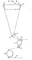
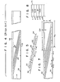
- FIG. 4 The manner in which video information is recorded on tape 26 in the VHS format is shown schematically in Figs. 4 and 5.
- line sync pulses 52 Between successive traces 50, there are line sync pulses 52. Traces 50 and pulses 52 are recorded in diagonal stripes 54, two of which contain the information for one TV frame (1/30 sec.).
- the frames are identified by sync pulses 56 which are recorded at an edge of the tape.
- Each frame consists of 525 scan lines (traces 50) of a TV display.
- Audio information is recorded on a width 58 at the other edge of tape 26.
- VCR 10 With VCR 10 on "play", video signals are picked up by drum 34 (Fig. 3) and transmitted to detector 12 through a control line 59.
- signals indicative of a dropout pass on line 60 to a counter 14a in the interface 14.
- Line sync pulses 52 are transmitted from VCR 10 to counter 14a on control line 62.
- Frame sync pulses 56 are transmitted to a memory array 14b and to counter 14a over lines 64 and 65.
- the line count of the first dropout in the previous frame is transferred to memory array 14b via bus 66.
- the computer is programmed to stop the tape when the first dropout in a predetermined length of tape reaches the field of microscope 22. Then.
- information as to that dropout is transmitted from memory array 14b, on bus 68, to computer 16 which is programmed to convert that information into data representative of the X-Y coordinates of the location of the dropout.
- the data is transmitted through a bus 70 to controller 20 which, in turn, transmits control signals through a line 72 to the X and/or Y stages of positioning table 28.
- the microscope 22 is positioned at the location of the dropout and it can be examined optically and/or photographed, as desired.
- Command signals for camera 23 are transmitted over control line 73 (Fig. 1).
- the data for each dropout in one or more lengths can be charted by printer 18 to facilitate an analysis of the durations and profiles of dropouts.
- a waveform recorder 76 (Hewlett Packard, Model 5180) can be used to correlate the located visual defect with an electronic signal.
- Demodulated video signal 78 from the detector 12 is the input for the recorder 76.
- Dropout signal 60 from the detector triggers the waveform recorder, thereby causing each dropout waveform to be stored.
- Computer 16 commands the waveform stored in the recorder 76 to be moved on bus 80 to the computer where it can be correlated to the microscope location and to a location pattern displayed on the screen of computer 16.
- a frame sync pulse 56 is detected as each frame begins. It is used to increment the memory array 14b and to clear and enable the counter 14a over control lines 64 and 65. Line sync pulses 52 on control line 62 also increment the counter 14a. If a dropout occurs, a signal from the dropout detector 12 stops the counter 14a. At the end of the frame, the counter 14a will have the number of the horizontal scan line that contains the dropout. The memory location corresponds to the frame. If there was no dropout in the frame, the line sync count will be 525, the number of lines per frame.
- the numbers in the counter 14a for the previous frame are transferred to the next memory location within array 14b via bus 66, the memory is incremented and the process is repeated for the next frame.
- the dropout locations in the memory array are transferred to the computer 1 6 . Since this information contains the frame and horizontal scan line of each dropout in this length of tape, the computer calculates the X-Y position of each dropout and sequentially sends this information to the controller 20 in order to position the microscope 22. This information is also displayed o the computer's cathode ray tube (CRT) to give a pattern of the dropouts on the tape.
- CTR cathode ray tube
- the predetermined length is twenty inches.
- the operator has the option of examining the next length, moving back or skipping forward to a new tape length. In all of these tape movements, the linear position of the tape is maintained by counting the frame sync pulses and through computer control of the VCR 10 via a control line 82.
- the equipment is configured to locate one dropout per frame and this set-up is satisfactory for most needs since the frequency of dropouts is low enough that it would be a rare occurrence to have more than one dropout per frame.
- the counter 14a has been modified so thai it can distinguish and exclusively account for defects of certain time intervals, specifically 5 ⁇ s, 10 ⁇ s and 15 ⁇ s defects.
- Computer 16 is programmed to calculate the cartesian X-Y coordinates using the formulae
- X R is the distance from the first frame sync pulse on the tape to the frame sync pulse beyond which a dropout is located.
- the distances X and X have been identified in Fig. 7.
- a profilometer 84 (Talysurf 5, Rank Taylor Hobson, Leicester, England) is mounted on positioning table 28'.
- Profilometer 84 has a stylus 86 which contacts a tape on shoe assembly 24'.
- This instrument is positioned over dropouts in the same manner as microscope 22 (Fig. 6). Topography of the tape is measured by traversing the stylus 86 over a selected area at the location of the dropout. This yields information as to high and low points and, therefore, as to the quality of the surface coating at the location of a dropout.
Landscapes
- Physics & Mathematics (AREA)
- Condensed Matter Physics & Semiconductors (AREA)
- General Physics & Mathematics (AREA)
- Manufacturing Of Magnetic Record Carriers (AREA)
Applications Claiming Priority (4)
| Application Number | Priority Date | Filing Date | Title |
|---|---|---|---|
| US67376784A | 1984-11-21 | 1984-11-21 | |
| US673767 | 1984-11-21 | ||
| US06/759,846 US4686563A (en) | 1984-11-21 | 1985-07-29 | Apparatus and method for locating dropouts |
| US759846 | 1985-07-29 |
Publications (3)
| Publication Number | Publication Date |
|---|---|
| EP0183481A2 true EP0183481A2 (fr) | 1986-06-04 |
| EP0183481A3 EP0183481A3 (en) | 1988-02-10 |
| EP0183481B1 EP0183481B1 (fr) | 1991-01-23 |
Family
ID=27101005
Family Applications (1)
| Application Number | Title | Priority Date | Filing Date |
|---|---|---|---|
| EP85308440A Expired EP0183481B1 (fr) | 1984-11-21 | 1985-11-20 | Appareil et procédé de localisation de pertes d'information |
Country Status (4)
| Country | Link |
|---|---|
| US (1) | US4686563A (fr) |
| EP (1) | EP0183481B1 (fr) |
| CA (1) | CA1286027C (fr) |
| DE (1) | DE3581503D1 (fr) |
Cited By (3)
| Publication number | Priority date | Publication date | Assignee | Title |
|---|---|---|---|---|
| US4812923A (en) * | 1984-11-21 | 1989-03-14 | E. I. Du Pont De Nemours And Company | Tape inspection apparatus |
| EP0303454A3 (fr) * | 1987-08-11 | 1989-05-17 | E.I. Du Pont De Nemours And Company | Procédé pour localiser et inspecter des défauts dans un disque magnétique |
| US4896227A (en) * | 1987-08-11 | 1990-01-23 | E. I. Dupont De Nemours & Co. | Method of locating and inspecting dropouts on a magnetic disc |
Families Citing this family (8)
| Publication number | Priority date | Publication date | Assignee | Title |
|---|---|---|---|---|
| US4794467A (en) * | 1986-05-10 | 1988-12-27 | Sony Corporation | Apparatus for automatically supplying and selectively reproducing a plurality of cassettes and for avoiding the reproducing of degraded signals |
| US5148291A (en) * | 1986-05-21 | 1992-09-15 | Canon Kabushiki Kaisha | Apparatus for displaying image signal drop-out |
| US4942609A (en) * | 1989-03-15 | 1990-07-17 | Magnetic Peripherals Inc. | Electronic flying integrity tester for disk drives |
| DE69024255T2 (de) * | 1989-05-11 | 1996-05-15 | Mitsubishi Electric Corp | Defektprüfvorrichtung für scheibenförmigen Datenaufzeichnungsträger |
| US5270874A (en) * | 1991-02-14 | 1993-12-14 | International Business Machines Corporation | Dropout simulation in a magnetic tape subsystem |
| JP3336581B2 (ja) * | 1992-10-19 | 2002-10-21 | 富士写真フイルム株式会社 | 追記型光ディスクの媒体検査方法およびシステム |
| US6034828A (en) * | 1994-04-11 | 2000-03-07 | Canon Kabushiki Kaisha | Recording of reproducing apparatus |
| DE10109441A1 (de) * | 2001-02-27 | 2002-09-12 | Mayah Comm Gmbh | Verfahren zum Erkennen audio-visueller Daten in Übertragungsnetzen, insbesondere dem Internet |
Family Cites Families (10)
| Publication number | Priority date | Publication date | Assignee | Title |
|---|---|---|---|---|
| GB1066472A (en) * | 1964-05-07 | 1967-04-26 | British Broadcasting Corp | Improvements in and relating to the testing of magnetic recording tape |
| US3525930A (en) * | 1968-03-28 | 1970-08-25 | Minnesota Mining & Mfg | Dropout counter |
| US3662158A (en) * | 1969-03-03 | 1972-05-09 | Kaitronics | Video tape analyzer and method |
| JPS5548009A (en) * | 1978-09-21 | 1980-04-05 | Omori Machinery | Packing method |
| JPS5639642A (en) * | 1979-09-10 | 1981-04-15 | Hitachi Denshi Ltd | Decoding circuit |
| JPS5757246A (en) * | 1980-09-25 | 1982-04-06 | Fuji Photo Film Co Ltd | Detecting and measuring apparatus for flaw |
| US4325134A (en) * | 1980-10-15 | 1982-04-13 | Rca Corporation | Video disc defect detector |
| JPS57171011A (en) * | 1981-04-13 | 1982-10-21 | Mitsubishi Motors Corp | Braking device for multicylinder four stroke cycle internal combustion engine |
| DE3246110A1 (de) * | 1981-12-15 | 1983-06-30 | Basf Ag, 6700 Ludwigshafen | Verfahren und anordnung zum auffinden von fehlerstellen auf einem magnetaufzeichnungstraeger |
| US4477890A (en) * | 1982-03-01 | 1984-10-16 | Discovision Associates | Mapping disc defect detector |
-
1985
- 1985-07-29 US US06/759,846 patent/US4686563A/en not_active Expired - Fee Related
- 1985-11-20 DE DE8585308440T patent/DE3581503D1/de not_active Expired - Lifetime
- 1985-11-20 EP EP85308440A patent/EP0183481B1/fr not_active Expired
- 1985-11-21 CA CA000495935A patent/CA1286027C/fr not_active Expired - Lifetime
Cited By (3)
| Publication number | Priority date | Publication date | Assignee | Title |
|---|---|---|---|---|
| US4812923A (en) * | 1984-11-21 | 1989-03-14 | E. I. Du Pont De Nemours And Company | Tape inspection apparatus |
| EP0303454A3 (fr) * | 1987-08-11 | 1989-05-17 | E.I. Du Pont De Nemours And Company | Procédé pour localiser et inspecter des défauts dans un disque magnétique |
| US4896227A (en) * | 1987-08-11 | 1990-01-23 | E. I. Dupont De Nemours & Co. | Method of locating and inspecting dropouts on a magnetic disc |
Also Published As
| Publication number | Publication date |
|---|---|
| CA1286027C (fr) | 1991-07-09 |
| EP0183481B1 (fr) | 1991-01-23 |
| US4686563A (en) | 1987-08-11 |
| DE3581503D1 (de) | 1991-02-28 |
| EP0183481A3 (en) | 1988-02-10 |
Similar Documents
| Publication | Publication Date | Title |
|---|---|---|
| EP0183481B1 (fr) | Appareil et procédé de localisation de pertes d'information | |
| US3646260A (en) | Electronic editing apparatus | |
| US5179449A (en) | Scene boundary detecting apparatus | |
| US20010017699A1 (en) | Method and measuring device for measuring a rotary tool | |
| DE69018581T2 (de) | Gerät zur Ermittlung des Abtastbereiches eines rotierenden Kopfes. | |
| US4340065A (en) | Method and apparatus for displaying electrocardiogram signals | |
| DE3938180A1 (de) | Verfahren und vorrichtungen zum aufzeichnen und wiedergeben von standbildern | |
| US6236429B1 (en) | Visualization system and method for a web inspection assembly | |
| US4812923A (en) | Tape inspection apparatus | |
| US4238777A (en) | Drop-out detecting system for video recording magnetic tape | |
| JPS61129704A (ja) | ドロツプアウトを突き止める装置及び方法 | |
| US3662158A (en) | Video tape analyzer and method | |
| JPH09210722A (ja) | 航空機の離着陸性能計測装置 | |
| US3693042A (en) | Rapid film reader/recorder utilizing movable cylindrical lens | |
| CN116423528A (zh) | 一种变压器油样品分拣方法及系统 | |
| US3866044A (en) | Apparatus for determining concentration profile of an element | |
| JPH05250601A (ja) | 磁気記録媒体に記録されたオーディオ−ビデオプログラムの品質を自動監視する方法 | |
| JP3052685B2 (ja) | テープ速度変動測定方法および記録トラック検査方法 | |
| JPH06295565A (ja) | 画像処理方法 | |
| US4280150A (en) | Helical scan video tape recorder guard band interference detector for generating control pulses at low tape speeds | |
| JPS61281910A (ja) | 移動標識の位置追跡装置 | |
| JPH04205761A (ja) | ビデオテープのドロップアウト位置表示装置 | |
| DE2413318A1 (de) | Zerstoerungsfreie markierung von fehlerstellen bei bandfoermigen flexiblen magnetischen speichermedien | |
| JPH03226697A (ja) | 原子炉用燃料外観検査装置ならびに該装置を使用した検査方法 | |
| US4115818A (en) | Apparatus for monitoring evolutive information |
Legal Events
| Date | Code | Title | Description |
|---|---|---|---|
| PUAI | Public reference made under article 153(3) epc to a published international application that has entered the european phase |
Free format text: ORIGINAL CODE: 0009012 |
|
| AK | Designated contracting states |
Kind code of ref document: A2 Designated state(s): BE DE FR GB IT LU NL |
|
| PUAL | Search report despatched |
Free format text: ORIGINAL CODE: 0009013 |
|
| AK | Designated contracting states |
Kind code of ref document: A3 Designated state(s): BE DE FR GB IT LU NL |
|
| 17P | Request for examination filed |
Effective date: 19880721 |
|
| 17Q | First examination report despatched |
Effective date: 19900420 |
|
| GRAA | (expected) grant |
Free format text: ORIGINAL CODE: 0009210 |
|
| AK | Designated contracting states |
Kind code of ref document: B1 Designated state(s): BE DE FR GB IT LU NL |
|
| ITF | It: translation for a ep patent filed | ||
| REF | Corresponds to: |
Ref document number: 3581503 Country of ref document: DE Date of ref document: 19910228 |
|
| ET | Fr: translation filed | ||
| PLBE | No opposition filed within time limit |
Free format text: ORIGINAL CODE: 0009261 |
|
| STAA | Information on the status of an ep patent application or granted ep patent |
Free format text: STATUS: NO OPPOSITION FILED WITHIN TIME LIMIT |
|
| 26N | No opposition filed | ||
| EPTA | Lu: last paid annual fee | ||
| PGFP | Annual fee paid to national office [announced via postgrant information from national office to epo] |
Ref country code: FR Payment date: 19940824 Year of fee payment: 10 |
|
| PGFP | Annual fee paid to national office [announced via postgrant information from national office to epo] |
Ref country code: DE Payment date: 19940902 Year of fee payment: 10 |
|
| PGFP | Annual fee paid to national office [announced via postgrant information from national office to epo] |
Ref country code: GB Payment date: 19940920 Year of fee payment: 10 |
|
| PGFP | Annual fee paid to national office [announced via postgrant information from national office to epo] |
Ref country code: BE Payment date: 19940921 Year of fee payment: 10 |
|
| PGFP | Annual fee paid to national office [announced via postgrant information from national office to epo] |
Ref country code: LU Payment date: 19941001 Year of fee payment: 10 |
|
| PGFP | Annual fee paid to national office [announced via postgrant information from national office to epo] |
Ref country code: NL Payment date: 19941130 Year of fee payment: 10 |
|
| PG25 | Lapsed in a contracting state [announced via postgrant information from national office to epo] |
Ref country code: LU Free format text: LAPSE BECAUSE OF NON-PAYMENT OF DUE FEES Effective date: 19951120 Ref country code: GB Effective date: 19951120 |
|
| PG25 | Lapsed in a contracting state [announced via postgrant information from national office to epo] |
Ref country code: BE Effective date: 19951130 |
|
| BERE | Be: lapsed |
Owner name: E.I. DU PONT DE NEMOURS AND CY Effective date: 19951130 |
|
| PG25 | Lapsed in a contracting state [announced via postgrant information from national office to epo] |
Ref country code: NL Effective date: 19960601 |
|
| GBPC | Gb: european patent ceased through non-payment of renewal fee |
Effective date: 19951120 |
|
| PG25 | Lapsed in a contracting state [announced via postgrant information from national office to epo] |
Ref country code: FR Effective date: 19960731 |
|
| NLV4 | Nl: lapsed or anulled due to non-payment of the annual fee |
Effective date: 19960601 |
|
| PG25 | Lapsed in a contracting state [announced via postgrant information from national office to epo] |
Ref country code: DE Effective date: 19960801 |
|
| REG | Reference to a national code |
Ref country code: FR Ref legal event code: ST |