EP0183487A2 - Elektrische Steckverbinder - Google Patents
Elektrische Steckverbinder Download PDFInfo
- Publication number
- EP0183487A2 EP0183487A2 EP85308468A EP85308468A EP0183487A2 EP 0183487 A2 EP0183487 A2 EP 0183487A2 EP 85308468 A EP85308468 A EP 85308468A EP 85308468 A EP85308468 A EP 85308468A EP 0183487 A2 EP0183487 A2 EP 0183487A2
- Authority
- EP
- European Patent Office
- Prior art keywords
- terminal
- retainer
- terminals
- connector
- passages
- Prior art date
- Legal status (The legal status is an assumption and is not a legal conclusion. Google has not performed a legal analysis and makes no representation as to the accuracy of the status listed.)
- Withdrawn
Links
Images

Classifications
-
- H—ELECTRICITY
- H01—ELECTRIC ELEMENTS
- H01R—ELECTRICALLY-CONDUCTIVE CONNECTIONS; STRUCTURAL ASSOCIATIONS OF A PLURALITY OF MUTUALLY-INSULATED ELECTRICAL CONNECTING ELEMENTS; COUPLING DEVICES; CURRENT COLLECTORS
- H01R13/00—Details of coupling devices of the kinds covered by groups H01R12/70 or H01R24/00 - H01R33/00
- H01R13/40—Securing contact members in or to a base or case; Insulating of contact members
- H01R13/42—Securing in a demountable manner
- H01R13/436—Securing a plurality of contact members by one locking piece or operation
- H01R13/4367—Insertion of locking piece from the rear
Definitions
- This invention relates to a multi-way electrical connector forming one part of a two part plug and socket connector unit.
- the invention may be embodied in either the plug connector or the socket connector of the unit, and preferably will be embodied in both connectors of the unit.
- British Patent 2081526 discloses an electrical connector wherein the terminals of the connector are retained within passages in the moulded synthetic resin body of the connector both by resilient lances on the terminals which engage behind shoulders in their respective passages, and by means of a retainer plate which is received within the moulded synthetic resin body and which co-operates with abutments provided on the terminals.
- a primary latching between the terminals and the body by way of the lances and a secondary latching by means of engagement of the retainer with both the body and the terminals. Both primary and secondary latching serving to retain the terminals against withdrawal of the body.
- miniature connector is used herein generally to denote an electrical connector having male terminals which are 2.50mm or less in width or female terminalswhich are arranged matingly to receive male terminals 2.50mm or less in width.
- a moulded synthetic resin body having therein a plurality of parallel passages receiving respective electrical terminals, said terminals being inserted into their respective passages from a rear end of the body, and each terminal including integral latch means intended to co-operate with the body to resist withdrawal of the terminal from its respective passage in a direction opposite the direction of insertion, each terminal further including an abutment, and the connector including a terminal retainer engageable with the body, said terminal retainer when engaged with the body, co-operating with said abutments of said terminals to prevent withdrawal of said terminals from their respective passages, said terminal retainer, when engaged with the body, embracing the rear end region of the body, having wall portions extending along opposite outer walls of the body from the rear end of the body towards the front end, and engaging beneath undercut shoulders of said walls of the body, whereby rearward movement of the terminal retainer relative to the body is prevented.
- terminal retainer is arranged to be slidably engaged with the body, the direction of sliding movement of the retainer relative to the body being at right-angles to the length of said passages.
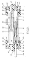
- each connector whether it be a plug part or a socket part includes a moulded synthetic resin body 11 having therein a plurality of passages 12 for receiving respective electrical terminals 13.
- the passages 12 are open at the rear end 14 of each body 11 to permit insertion of the terminals into their respective passages from the rear end of the body 11.
- the terminals 13 will be accessible at the front end of their _respective passage for mating engagement with a corresponding terminal when a pair of connectors of a connector unit are interengaged.
- each terminal 13 Prior to insertion into its respective passage 12, each terminal 13 will have a respective electrical lead 13a secured thereto in the usual manner. Thus a plurality of leads 13a will protrude from the rear end 14 of each body 11.
- each terminal and each passage includes stop means limiting movement of the terminal relative to its passage in the insertion direction, and furthermore each terminal will include at least one resilient lance which is intended to co-operate with a shoulder in the wall of its respective passage to resist withdrawal of the terminal from its respective passage.
- Each connector further includes a terminal retainer 15 moulded in synthetic resin material, and preferably of a colour which contrasts with the colour of the body 11,
- the retainer 15 is intended to embrace the rear end portion of its respective body 11, and thus is of a length slightly greater than the equivalent dimension of its respective body.
- the retainer In transverse cross- section the retainer is generally U-shaped having a pair of parallel wall portions 16 formed adjacent their free ends with inwardly directed longitudinally extending ribs 17.
- the base region 18 of the U-shape retainer 15 is divided into three parallel sections by two parallel slots 19 which extend longitudinally of the retainer 15 from one end thereof.
- the slots 19 do not extend completely to the opposite end of the retainer, and thus the three portions of the base of the retainer defined by the slots 19 are integral with one another at one end of the retainer.
- the central bar of the retainer defined between the two slots 19 is indicated at 21 in the drawings and as can be seen clearly in Figure 3 projects at its free end beyond the free ends of the two portions 22 on opposite sides thereof.
- the portions 22 are formed internally with integral longitudinally extending flanges 23 which lie parallel to the wall portions 16.
- the flat, longitudinally extending surfaces of the flanges 23 and the bar 21 which lie at right angles to the wall portions 16 and within the retainer 15 are co-planar.
- the passages 12 are arranged in two parallel rows, the extent of the rows being in a direction at right angles to the length of the passages and parallel to the length of the retainer 15.
- the retainer 15 is engaged with the respective body 11 in the following manner.
- the leads 13a will be protruding from the rear end of the body generally in two parallel rows.
- the retainer 15 is aligned with the body 11 and is moved relative to the body 11 in the direction of the length of the retainer 15 and at right angles to the passages 12.
- the body 11 enters between the walls 16 and the leads 13a of the two rows of leads enter, respectively, the slots 19 of the retainer 15.
- the retainer 15 is slid across the end of the body 11, embracing the rear end of the body 11 until the closed end 15a of the retainer abuts the body and prevents further sliding movement. At this point the protruding end of the central bar 16 will have been received within a stirrup 16a integral with the body 11.
- the retainer 15 is held against movement relative to the body 11 in the direction of the length of the passages in one direction by abutment of the interior of the retainer with the rear end of the body, and in the opposite direction by engagement of the ribs 17 beneath undercut shoulders 17a of the opposite outer walls of the body 11. If desired some form of latch arrangement can be provided to resist withdrawal of the retainer 15 from the body 11 in a direction opposite to that in which it is slidably engaged with the body 11.
- each terminal 13 includes a pair of outwardly directed abutments 24 which, when the terminal is fully inserted into its respective passage, lie at the rear end of the respective passage 12.
- the lower surface of the bar 21 overlies an abutment 24 of each of the terminals in both parallel rows, and the co-planar lower surface of each flange 23 overlies the other abutment 24 of the terminals of the respective row.
- Figures 1 to 4 are somewhat simplified diagrammatic representations, and thus there are changes in detail between the shapes and dimensions illustrated in Figures 1 to 4, and the equivalent shapes and dimensions in Figure 5.
- Figure 5 illustrates a more practical embodiment. It can also be seen in Figure 5 that the two body parts 11 are latched together by integral latch parts including an integral resilient finger 25 on one of the body parts 11 which engages beneath a shoulder 26 of the other body when the two connectors of the unit are inter-engaged.
- the terminals 13 in the unit shown in Figure 5 are male terminals having a width not exceeding 2.50 mm.
- the mating female terminals (not shown) will of course be dimensioned matingly to receive the male terminals.
Landscapes
- Connector Housings Or Holding Contact Members (AREA)
Applications Claiming Priority (2)
| Application Number | Priority Date | Filing Date | Title |
|---|---|---|---|
| GB8430151 | 1984-11-29 | ||
| GB848430151A GB8430151D0 (en) | 1984-11-29 | 1984-11-29 | Electrical connectors |
Publications (2)
| Publication Number | Publication Date |
|---|---|
| EP0183487A2 true EP0183487A2 (de) | 1986-06-04 |
| EP0183487A3 EP0183487A3 (de) | 1987-07-22 |
Family
ID=10570453
Family Applications (1)
| Application Number | Title | Priority Date | Filing Date |
|---|---|---|---|
| EP85308468A Withdrawn EP0183487A3 (de) | 1984-11-29 | 1985-11-21 | Elektrische Steckverbinder |
Country Status (2)
| Country | Link |
|---|---|
| EP (1) | EP0183487A3 (de) |
| GB (1) | GB8430151D0 (de) |
Cited By (4)
| Publication number | Priority date | Publication date | Assignee | Title |
|---|---|---|---|---|
| DE9003013U1 (de) * | 1990-03-12 | 1991-07-11 | Grote & Hartmann Gmbh & Co Kg, 5600 Wuppertal | Elektrischer Steckverbinder mit zwei in Richtung seiner Längsmittelachse lösbar zusammensteckbar und miteinander verrastbaren Steckerteilen |
| FR2666935A1 (fr) * | 1990-09-18 | 1992-03-20 | Labinal | Perfectionnements aux elements de boitiers de connecteurs electriques. |
| EP0496275A1 (de) * | 1991-01-25 | 1992-07-29 | Kabelwerke Reinshagen GmbH | Elektrischer Verbinder mit einem Verriegelungsteil für die Kontaktelemente |
| EP0795933A3 (de) * | 1996-03-11 | 1998-08-19 | Framatome Connectors International | Elektrischer Verbinder mit zusätzlicher Verrieglung |
Family Cites Families (4)
| Publication number | Priority date | Publication date | Assignee | Title |
|---|---|---|---|---|
| US3501736A (en) * | 1967-12-07 | 1970-03-17 | Whitaker Cable Corp | Multiple terminal electrical connector |
| GB1491217A (en) * | 1975-04-29 | 1977-11-09 | Amp Inc | Electrical connector housing |
| NL7901885A (nl) * | 1978-03-08 | 1979-09-11 | Baensch Tetra Werke | Eenfase-synchroonmotor. |
| GB2081526B (en) * | 1980-07-30 | 1984-09-12 | Lucas Industries Ltd | Electrical connector |
-
1984
- 1984-11-29 GB GB848430151A patent/GB8430151D0/en active Pending
-
1985
- 1985-11-21 EP EP85308468A patent/EP0183487A3/de not_active Withdrawn
Cited By (5)
| Publication number | Priority date | Publication date | Assignee | Title |
|---|---|---|---|---|
| DE9003013U1 (de) * | 1990-03-12 | 1991-07-11 | Grote & Hartmann Gmbh & Co Kg, 5600 Wuppertal | Elektrischer Steckverbinder mit zwei in Richtung seiner Längsmittelachse lösbar zusammensteckbar und miteinander verrastbaren Steckerteilen |
| FR2666935A1 (fr) * | 1990-09-18 | 1992-03-20 | Labinal | Perfectionnements aux elements de boitiers de connecteurs electriques. |
| EP0477044A1 (de) * | 1990-09-18 | 1992-03-25 | Société anonyme dite: LABINAL | Verbesserungen in Bezug auf Gehäuseteile von elektrischen Verbindern |
| EP0496275A1 (de) * | 1991-01-25 | 1992-07-29 | Kabelwerke Reinshagen GmbH | Elektrischer Verbinder mit einem Verriegelungsteil für die Kontaktelemente |
| EP0795933A3 (de) * | 1996-03-11 | 1998-08-19 | Framatome Connectors International | Elektrischer Verbinder mit zusätzlicher Verrieglung |
Also Published As
| Publication number | Publication date |
|---|---|
| GB8430151D0 (en) | 1985-01-09 |
| EP0183487A3 (de) | 1987-07-22 |
Similar Documents
| Publication | Publication Date | Title |
|---|---|---|
| US4634204A (en) | Electrical connector with connector position assurance/assist device | |
| US4959023A (en) | Electrical connector | |
| JP2581476Y2 (ja) | コネクタ | |
| US5122080A (en) | Electrical connector | |
| US4319799A (en) | Electrical connector with group terminal lock | |
| EP0644619B1 (de) | Verfahren und Vorrichtung zum doppeltem Sichern eines Anschlusses in einem Verbinder | |
| US5944547A (en) | Connector shorting bar retention | |
| EP0676828A2 (de) | Steckverbinder | |
| US5496184A (en) | Header assembly for printed circuit board | |
| EP0582866B1 (de) | Elektrischer Verbinder mit sekundärem Sperrmechanismus | |
| GB2024538A (en) | Electrical connector terminals | |
| US5033980A (en) | Electrical connector with a double locking structure for terminals | |
| CA1069195A (en) | Electrical connector for printed circuit board | |
| EP0978905B1 (de) | Verbinder | |
| US5660556A (en) | Electrical connectors | |
| US20020086588A1 (en) | Connector | |
| DE69838236T2 (de) | Ein Verbinder mit Verriegelung | |
| US20020081912A1 (en) | Connector | |
| US5651704A (en) | Electrical connector with terminal retainer | |
| CS41592A3 (en) | Plug-in electric connecting block and a connector therefor | |
| DE69613197T2 (de) | Elektrische Verbinderanordnung | |
| US4971579A (en) | Electrical connector with removable terminal guide and lock | |
| GB2071926A (en) | A connector housing with contact retaining means | |
| EP0183487A2 (de) | Elektrische Steckverbinder | |
| DE19911686A1 (de) | Verbindungsvorrichtung |
Legal Events
| Date | Code | Title | Description |
|---|---|---|---|
| PUAI | Public reference made under article 153(3) epc to a published international application that has entered the european phase |
Free format text: ORIGINAL CODE: 0009012 |
|
| AK | Designated contracting states |
Kind code of ref document: A2 Designated state(s): DE FR GB IT NL SE |
|
| PUAL | Search report despatched |
Free format text: ORIGINAL CODE: 0009013 |
|
| AK | Designated contracting states |
Kind code of ref document: A3 Designated state(s): DE FR GB IT NL SE |
|
| 17P | Request for examination filed |
Effective date: 19871110 |
|
| 17Q | First examination report despatched |
Effective date: 19891120 |
|
| STAA | Information on the status of an ep patent application or granted ep patent |
Free format text: STATUS: THE APPLICATION IS DEEMED TO BE WITHDRAWN |
|
| 18D | Application deemed to be withdrawn |
Effective date: 19900402 |
|
| RIN1 | Information on inventor provided before grant (corrected) |
Inventor name: CRINSON, ANDREW LEE |