EP0183502B1 - Optische Pulserzeugungssysteme - Google Patents
Optische Pulserzeugungssysteme Download PDFInfo
- Publication number
- EP0183502B1 EP0183502B1 EP85308531A EP85308531A EP0183502B1 EP 0183502 B1 EP0183502 B1 EP 0183502B1 EP 85308531 A EP85308531 A EP 85308531A EP 85308531 A EP85308531 A EP 85308531A EP 0183502 B1 EP0183502 B1 EP 0183502B1
- Authority
- EP
- European Patent Office
- Prior art keywords
- light
- optical
- pulses
- output
- fibre
- Prior art date
- Legal status (The legal status is an assumption and is not a legal conclusion. Google has not performed a legal analysis and makes no representation as to the accuracy of the status listed.)
- Expired - Lifetime
Links
- 230000003287 optical effect Effects 0.000 title claims abstract description 56
- 230000001427 coherent effect Effects 0.000 claims abstract description 28
- 239000013307 optical fiber Substances 0.000 claims description 23
- 239000000835 fiber Substances 0.000 claims description 22
- 238000001514 detection method Methods 0.000 claims description 7
- 230000035559 beat frequency Effects 0.000 claims description 5
- 230000003111 delayed effect Effects 0.000 abstract description 3
- 230000000644 propagated effect Effects 0.000 description 3
- 239000000523 sample Substances 0.000 description 3
- 239000004065 semiconductor Substances 0.000 description 3
- 238000006073 displacement reaction Methods 0.000 description 2
- 230000001934 delay Effects 0.000 description 1
- 238000010348 incorporation Methods 0.000 description 1
- 238000012986 modification Methods 0.000 description 1
- 230000004048 modification Effects 0.000 description 1
- 230000010363 phase shift Effects 0.000 description 1
Images
Classifications
-
- H—ELECTRICITY
- H01—ELECTRIC ELEMENTS
- H01S—DEVICES USING THE PROCESS OF LIGHT AMPLIFICATION BY STIMULATED EMISSION OF RADIATION [LASER] TO AMPLIFY OR GENERATE LIGHT; DEVICES USING STIMULATED EMISSION OF ELECTROMAGNETIC RADIATION IN WAVE RANGES OTHER THAN OPTICAL
- H01S3/00—Lasers, i.e. devices using stimulated emission of electromagnetic radiation in the infrared, visible or ultraviolet wave range
- H01S3/005—Optical devices external to the laser cavity, specially adapted for lasers, e.g. for homogenisation of the beam or for manipulating laser pulses, e.g. pulse shaping
- H01S3/0057—Temporal shaping, e.g. pulse compression, frequency chirping
-
- G—PHYSICS
- G02—OPTICS
- G02F—OPTICAL DEVICES OR ARRANGEMENTS FOR THE CONTROL OF LIGHT BY MODIFICATION OF THE OPTICAL PROPERTIES OF THE MEDIA OF THE ELEMENTS INVOLVED THEREIN; NON-LINEAR OPTICS; FREQUENCY-CHANGING OF LIGHT; OPTICAL LOGIC ELEMENTS; OPTICAL ANALOGUE/DIGITAL CONVERTERS
- G02F1/00—Devices or arrangements for the control of the intensity, colour, phase, polarisation or direction of light arriving from an independent light source, e.g. switching, gating or modulating; Non-linear optics
- G02F1/01—Devices or arrangements for the control of the intensity, colour, phase, polarisation or direction of light arriving from an independent light source, e.g. switching, gating or modulating; Non-linear optics for the control of the intensity, phase, polarisation or colour
- G02F1/21—Devices or arrangements for the control of the intensity, colour, phase, polarisation or direction of light arriving from an independent light source, e.g. switching, gating or modulating; Non-linear optics for the control of the intensity, phase, polarisation or colour by interference
-
- G—PHYSICS
- G02—OPTICS
- G02F—OPTICAL DEVICES OR ARRANGEMENTS FOR THE CONTROL OF LIGHT BY MODIFICATION OF THE OPTICAL PROPERTIES OF THE MEDIA OF THE ELEMENTS INVOLVED THEREIN; NON-LINEAR OPTICS; FREQUENCY-CHANGING OF LIGHT; OPTICAL LOGIC ELEMENTS; OPTICAL ANALOGUE/DIGITAL CONVERTERS
- G02F2/00—Demodulating light; Transferring the modulation of modulated light; Frequency-changing of light
- G02F2/002—Demodulating light; Transferring the modulation of modulated light; Frequency-changing of light using optical mixing
-
- G—PHYSICS
- G02—OPTICS
- G02F—OPTICAL DEVICES OR ARRANGEMENTS FOR THE CONTROL OF LIGHT BY MODIFICATION OF THE OPTICAL PROPERTIES OF THE MEDIA OF THE ELEMENTS INVOLVED THEREIN; NON-LINEAR OPTICS; FREQUENCY-CHANGING OF LIGHT; OPTICAL LOGIC ELEMENTS; OPTICAL ANALOGUE/DIGITAL CONVERTERS
- G02F1/00—Devices or arrangements for the control of the intensity, colour, phase, polarisation or direction of light arriving from an independent light source, e.g. switching, gating or modulating; Non-linear optics
- G02F1/01—Devices or arrangements for the control of the intensity, colour, phase, polarisation or direction of light arriving from an independent light source, e.g. switching, gating or modulating; Non-linear optics for the control of the intensity, phase, polarisation or colour
- G02F1/21—Devices or arrangements for the control of the intensity, colour, phase, polarisation or direction of light arriving from an independent light source, e.g. switching, gating or modulating; Non-linear optics for the control of the intensity, phase, polarisation or colour by interference
- G02F1/212—Mach-Zehnder type
-
- G—PHYSICS
- G02—OPTICS
- G02F—OPTICAL DEVICES OR ARRANGEMENTS FOR THE CONTROL OF LIGHT BY MODIFICATION OF THE OPTICAL PROPERTIES OF THE MEDIA OF THE ELEMENTS INVOLVED THEREIN; NON-LINEAR OPTICS; FREQUENCY-CHANGING OF LIGHT; OPTICAL LOGIC ELEMENTS; OPTICAL ANALOGUE/DIGITAL CONVERTERS
- G02F1/00—Devices or arrangements for the control of the intensity, colour, phase, polarisation or direction of light arriving from an independent light source, e.g. switching, gating or modulating; Non-linear optics
- G02F1/01—Devices or arrangements for the control of the intensity, colour, phase, polarisation or direction of light arriving from an independent light source, e.g. switching, gating or modulating; Non-linear optics for the control of the intensity, phase, polarisation or colour
- G02F1/21—Devices or arrangements for the control of the intensity, colour, phase, polarisation or direction of light arriving from an independent light source, e.g. switching, gating or modulating; Non-linear optics for the control of the intensity, phase, polarisation or colour by interference
- G02F1/225—Devices or arrangements for the control of the intensity, colour, phase, polarisation or direction of light arriving from an independent light source, e.g. switching, gating or modulating; Non-linear optics for the control of the intensity, phase, polarisation or colour by interference in an optical waveguide structure
- G02F1/2252—Devices or arrangements for the control of the intensity, colour, phase, polarisation or direction of light arriving from an independent light source, e.g. switching, gating or modulating; Non-linear optics for the control of the intensity, phase, polarisation or colour by interference in an optical waveguide structure in optical fibres
-
- G—PHYSICS
- G02—OPTICS
- G02F—OPTICAL DEVICES OR ARRANGEMENTS FOR THE CONTROL OF LIGHT BY MODIFICATION OF THE OPTICAL PROPERTIES OF THE MEDIA OF THE ELEMENTS INVOLVED THEREIN; NON-LINEAR OPTICS; FREQUENCY-CHANGING OF LIGHT; OPTICAL LOGIC ELEMENTS; OPTICAL ANALOGUE/DIGITAL CONVERTERS
- G02F2203/00—Function characteristic
- G02F2203/26—Pulse shaping; Apparatus or methods therefor
Definitions
- This invention relates to optical pulse generating arrangements and relates more specifically to differential delay coherent pulse generating arrangements suitable for use in differential delay heterodyne interferometers and to optical devices for incorporation in such differential delay optical coherent pulse generating arrangements.
- a known form of optical pulse generating arrangement is shown in patent document WO83/03684.
- This document discloses a fibre optic sensor having a light source connected to a first fibre optic waveguide having a delay loop and modulator and is coupled to a second fibre optic waveguide by two couplers. One end of the second fibre optic waveguide forms the probe and the other end is connected to a detector. The probe directs light toward a surface of a test sample and the counterpropagated waves experience a phase shift proportional to the amplitude of displacement of the surface.
- an optical device for generation and interferometric detection of differential optical coherent pulses comprising: a coherent light source emitting continuous wave light; beam splitting means to divide said light into two optical paths; delay means to delay the light beam in one of said paths relative to the light beam in the other of said paths; optical switching means arranged to receive the two light beams from said two optical light paths and having first and second switching states to sequentially select the light from each path and direct said light to an output fibre connected to an output of said switching means, to produce two coherent light pulses in predetermined time displaced relationship in said output fibre, frequency shifting means arranged to produce a frequency difference between the two light pulses; and a light detector, characterized in that said optical switching means has a third switching state different from the first and second switching states which is arranged such that the light pulses reflected back along said output fibre to the output of said optical switching means are directed onto said light detector to produce a beat frequency signal.
- the delaying of one of the divided light beams relative to the other and the delay introduced by the sequential optical switching means serves to provide total coherence between the light content of the two coherent pulses, that is to say, the two time displaced output pulses are both derived from the same period of light from the coherent light source and consequently the latter may have a relatively short coherent length, thus enabling for example a semiconductor laser to be used instead of the less compact and less rugged gas laser.
- the frequency difference between the two output pulses may be produced by means of a frequency shifting device introduced into either of the two light paths referred to above or alternatively, it may be introduced into the system following the optical switching means, in which case the frequency shifting device will be arranged to shift the frequencies of both time displaced pulses relative to one another to produce the requisite frequency differential.
- the optical paths are preferably optical fibres and the optical switching function and the frequency shifting function may be performed by means of a Bragg cell which receives the light beams from the respective paths and which is driven by two different signals so that the two light beams are alternatively deflected into a common output optical fibre as the Bragg cell is driven in turn by the two different frequencies.
- the two time displaced coherent pulses of different frequencies produced by the pulse generating arrangement may be launched into a spliced sensing optical fibre.
- the light pulses reflected from consecutive partially reflecting splices equally spaced along the sensing fibre in dependence upon the time displacement between the coherent pulses interfere with one another and pass back through the aforesaid optical switching means without deflection of the pulses to heterodyning means (e.g. square law photo-detector) to produce an electrical beat frequency signal.
- the optical switching means may comprise a Bragg cell which is switched off to allow the reflected light pulses to pass to the heterodyning detector means without being deflected.
- Phase modulation of this beat signal will vary with changes in the lengths of the elements of the sensing fibre between adjacent splices.
- changes in length of the optical fibre elements can be determined.
- Such changes in length of the fibre elements may for example be produced by acoustic signals impinging on the sensing fibre or by temperature or pressure changes etc.
- Patent No. GB 2126820B is hereby directed to Patent No. GB 2126820B.
- the time displaced pulses of different frequency derived from the optical pulse generating arrangement according to the present invention could be launched through a beam splitting arrangement into an interferometer hydrophone of the form fully described in Patent No. GB 2125957B.
- an optical device for generation and interferometric detection of differential optical coherent pulses comprising: a coherent light source emitting continuous wave light; and a frequency shifting Bragg cell arranged to receive said light and driven alternately by two different frequency signals to produce output pulses of different frequency for launching into an output optical fibre and which additionally is arranged to switch partially reflected optical pulses returned over said output optical fibre to light detecting means when the Bragg cell is switched off.
- This second aspect of the present invention may be applied to a differential delay heterodyne interferometer requiring pairs of optical pulses to be generated having frequencies differing from one another by the desired heterodyne frequency.
- the utilisation of the Bragg cell both as frequency shifting means and optical switching means for the returned reflected light pulses enables the use of "lossy" beam splitting means for diverting returned reflected light pulses to heterodyning detection means to be avoided.
- attention is hereby directed to our co-pending Patent Application No. 2126820A.
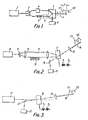
- the light output from a semiconductor continuous wave coherent light source 1 is divided and directed along two optical fibre paths by means of a beam splitter 2.
- One of these optical fibre paths includes optical delay means such as a coiled optical fibre 3 for delaying the propagated light in the path concerned relative to the propagated light in the other path.
- the other optical fibre path includes frequency shifting means 4 (e.g Bragg cell) for producing a frequency shift in the propagated light.
- Optical switching means 5 is arranged for sequentially selecting the delayed non-frequency shifted light and the non-delayed frequency shifted light outputs from the respective optical paths. This sequential selection serves to produce time-displaced output pulses V1 and V2 of different frequencies.
- the light content of the pulses V1 and V2 is derived from the same period of light from the light source 1 and consequently the light pulses V1 and V2 are totally coherent. This allows the choice of a more rugged and compact semiconductor laser light source 1 having a relatively short coherent length to be made instead of a gas laser light source.
- the frequency shifting means 4 may alternatively be connected in the same optical fibre path as the optical delay means 3, or it may be connected on the output side of the optical switching means 5. In the latter case it will of course be necessary for the respective pulses to be frequency shifted by different amounts.
- the coherent light pulses V1 and V2 may be utilised in heterodyne interferometers of the forms described in our co-pending Patent Applications Nos. 2126820A (F.12973) and 8207961 (F.12943) but in the first-mentioned patent application the time-displaced different frequency optical pulses V1 and V2 differing in frequency by the requisite heterodyne frequency will be partially reflected back to the optical switching means 5 by equally-spaced splices provided between consecutive optical fibre elements of an acoustic signal or other sensing fibre (not shown).
- phase modulation of the beat signal will vary with changes in length of the fibre elements between consecutive splices of the sensor fibre, due for example to the impingement of acoustic signals thereon, and may be suitably detected and measured.
- FIG. 2 of the drawings shows an arrangement in which the optical switching means and the frequency shifting means of the Figure 1 arrangement are constituted by a single Bragg cell 7.
- Continuous wave light from a coherent light source 8 is divided and directed into two optical fibre paths by means of a beam splitting bi-prism 9 and convex lens 10.
- the respective paths may comprise a linear optical fibre 11 and a coiled optical fibre 12 which delays the light beams in the two paths relative to one another by time T.
- the light beams emerging from the respective paths are received by the Bragg cell 7.
- the Bragg cell is driven alternately by two signals of frequencies f1 and f2 whereby the Bragg cell produces output pulses V1 and V2 displaced from one another by time T.
- pulses V1 and V2 are launched by a convex lens 13 into an output fibre 14.
- the output pulses V1 and V2 are totally coherent and may be utilised in the heterodyne interferometers forming the subject of our previously mentioned co-pending patent applications.
- the Bragg cell After generation of the pulses V1 and V2 the Bragg cell will be switched off so that partially reflected light pulses returning along the optical fibre 14 from splices of an optical fibre sensor will pass through the Bragg cell 7 without deflection to light detecting means 15, such as a photo-detector, conveniently after reflection by a reflecting mirror 16.
- light detecting means 15 such as a photo-detector
- heterodyne beat frequency signals will be produced and phase modulation can be detected and measured for detecting the impingement of acoustic signals on the optical fibre sensor.
- the linear optical fibre 11 may be dispensed with and one of the light beams from the beam splitter fed directly into the Bragg cell. This modification may involve the introduction of a mirror into the other path including the delay coil.
- FIG. 3 of the drawings shows an arrangement suitable for use in a heterodyne interferometer of the kind utilising a relatively long coherent length light source 17 (i.e. gas laser).
- a relatively long coherent length light source 17 i.e. gas laser
- the continuous wave light output of frequency V derived from the source 17 is fed into a Bragg cell 18.
- the Bragg cell 18 is driven alternately by signals of frequencies f1 and f2 so that the Bragg cell produces output pulses V1 and V2 displaced from one another by time T, the frequency difference f1 - f2 being small enough that both optical pulses are launched into the output fibre.
- These pulses V1 and V2 are launched into the output optical fibre 19 by means of a convex lens 20.
- Bragg cell 18 as an optical switch and frequency shifter enables the relatively "lossy" beam splitter of Patent Application No. 2126820A to be dispensed with and thereby enhances the efficiency of the interferometer arrangement.
Landscapes
- Physics & Mathematics (AREA)
- Nonlinear Science (AREA)
- Optics & Photonics (AREA)
- General Physics & Mathematics (AREA)
- Electromagnetism (AREA)
- Engineering & Computer Science (AREA)
- Plasma & Fusion (AREA)
- Optical Communication System (AREA)
- Instruments For Measurement Of Length By Optical Means (AREA)
- Optical Radar Systems And Details Thereof (AREA)
- Surgical Instruments (AREA)
- Semiconductor Lasers (AREA)
- Pyrane Compounds (AREA)
- Microscoopes, Condenser (AREA)
- Optical Transform (AREA)
- Lasers (AREA)
- Investigating, Analyzing Materials By Fluorescence Or Luminescence (AREA)
- Investigating Or Analysing Materials By Optical Means (AREA)
Claims (3)
- Ein optisches Gerät für die Erzeugung und interferometrische Bestimmung von differential, optisch kohärenten Impulsen, umfassend:
eine kohärente Lichtquelle (1), für das Emittieren von Licht mit ungedämpfter Welle;
Strahlenaufspaltungsmittel (2), um das besagte Licht in zwei optische Pfade aufzuteilen;
Verzögerungsmittel (3), um den Lichtstrahl in einem der besagten Pfade relativ zum Lichtstrahl im anderen der besagten Pfade zu verzögern;
optische Schaltmittel (5), angeordnet um die zwei Lichtstrahlen von besagten zwei optischen Lichtpfaden zu empfangen und die einen ersten und zweiten Schaltzustand aufweisen, um sequentiell das Licht von jedem Pfad auszuwählen und das besagte Licht an eine Ausgabefaser zu richten, die an die Ausgabe von besagten Schaltmittel angeschlossen ist, um zwei kohärente Lichtimpulse in vorbestimmter, zeitlich verschobener Beziehung in besagter Ausgabefaser zu erzeugen;
Frequenzschiebemittel (4), angeordnet um eine Frequenzdifferenz zwischen den beiden besagten Lichtimpulsen zu erzeugen; und einen Lichtdetektor (6),
dadurch gekennzeichnet, dass die besagten optischen Schaltmittel einen dritten Schaltzustand aufweisen, der verschieden ist vom ersten und zweiten Schaltzustand und der derart angeordnet ist, dass die entlang der besagten Ausgabefaser zur Ausgabe von besagten optischen Schaltmittel zurückreflektierten Lichtimpulse auf besagten Lichtdetektor gerichtet sind, um ein Schwebefrequenzsignal zu erzeugen. - Ein optisches Gerät nach Anspruch 1, dadurch gekennzeichnet, dass die optischen Schaltmittel und Frequenzschiebemittel durch eine einzige Bragg'sche Zelle (7) gebildet werden, die die Lichtstrahlen von den jeweiligen optischen Pfaden empfängt und die durch zwei unterschiedliche Frequenzsignale (f1, f2) betrieben wird, so dass die zwei Lichtstrahlen alternativ zur Ausgabefaser (14) gerichtet werden, und in welchem die Bragg'sche Zelle, wenn sie nachfolgend der Erzeugung der seitlich verschobenen Lichtimpulse in ihrem ausgeschalteten Zustand ist, reflektiertem Licht ermöglicht entlang der Ausgabefaser (14) zurückzukehren, um durch die Bragg'sche Zelle auf den Lichtdetektor (15) zu gelangen.
- Ein optisches Gerät für das Erzeugen und interferometrische Bestimmen von differential, optisch, kohärenten Impulsen, umfassend:
eine kohärente Lichtquelle (17), für das Aussenden von Licht mit ungedämpfter Welle; und
eine Frequenzschiebe-Bragg'sche Zelle (18), angeordnet um das besagte Licht zu empfangen und alternativ durch zwei unterschiedliche Frequenzsignale (f1, f2) betrieben zu werden, um Ausgabeimpulse von unterschiedlicher Frequenz zu erzeugen, um in eine Ausgabe-optische Faser (19) eingegeben zu werden, und die zusätzlich angeordnet ist um partiell reflektierte, optische Impulse, die über die besagte Ausgabe optische Faser zurückgekehrt sind, an Licht-detektierende Mittel (21) zu schalten, wenn die Bragg'sche Zelle ausgeschaltet ist.
Priority Applications (1)
| Application Number | Priority Date | Filing Date | Title |
|---|---|---|---|
| AT85308531T ATE86395T1 (de) | 1984-11-24 | 1985-11-25 | Optische pulserzeugungssysteme. |
Applications Claiming Priority (2)
| Application Number | Priority Date | Filing Date | Title |
|---|---|---|---|
| GB8429755 | 1984-11-24 | ||
| GB8429755 | 1984-11-24 |
Publications (3)
| Publication Number | Publication Date |
|---|---|
| EP0183502A2 EP0183502A2 (de) | 1986-06-04 |
| EP0183502A3 EP0183502A3 (en) | 1989-03-08 |
| EP0183502B1 true EP0183502B1 (de) | 1993-03-03 |
Family
ID=10570245
Family Applications (1)
| Application Number | Title | Priority Date | Filing Date |
|---|---|---|---|
| EP85308531A Expired - Lifetime EP0183502B1 (de) | 1984-11-24 | 1985-11-25 | Optische Pulserzeugungssysteme |
Country Status (5)
| Country | Link |
|---|---|
| US (1) | US4856092A (de) |
| EP (1) | EP0183502B1 (de) |
| AT (1) | ATE86395T1 (de) |
| AU (1) | AU576643B2 (de) |
| DE (1) | DE3587140T2 (de) |
Families Citing this family (14)
| Publication number | Priority date | Publication date | Assignee | Title |
|---|---|---|---|---|
| US4729620A (en) * | 1984-05-25 | 1988-03-08 | Litton Systems, Inc. | Fiber optic frequency shifter |
| US4856092A (en) * | 1984-11-24 | 1989-08-08 | Plessey Overseas Limited | Optical pulse generating arrangements |
| GB2205172B (en) * | 1987-05-23 | 1991-01-30 | Gen Electric Plc | Delaying an amplitude-modulated optical signal |
| US4893352A (en) * | 1987-06-30 | 1990-01-09 | Massachusetts Institute Of Technology | Optical transmitter of modulated signals |
| GB8716776D0 (en) * | 1987-07-16 | 1987-11-18 | Plessey Co Plc | Optical sensing systems |
| JPH01223837A (ja) * | 1988-03-03 | 1989-09-06 | Nec Corp | 光多値送信機 |
| FR2642857B1 (fr) * | 1988-12-23 | 1991-04-12 | Thomson Csf | Dispositif de traitement optoelectronique du signal, notamment pour le traitement de signaux en hyperfrequence |
| JP2719397B2 (ja) * | 1989-04-24 | 1998-02-25 | 日本電信電話株式会社 | 超短光パルス変調回路 |
| US5144375A (en) * | 1990-05-10 | 1992-09-01 | At&T Bell Laboratories | Sagnac optical logic gate |
| US5101456A (en) * | 1990-11-07 | 1992-03-31 | At&T Bell Laboratories | Predistortion apparatus for optical logic device |
| EP0987844B1 (de) * | 1998-09-17 | 2005-04-27 | Corning Photonic Technologies Inc. | Optische Vorrichtung für Bearbeitung einer optischen Impulse |
| US6542269B1 (en) | 1998-09-17 | 2003-04-01 | Corning O.T.I., Inc. | Optical device for processing an optical impulse |
| FR2867620B1 (fr) * | 2004-03-12 | 2008-10-24 | Thales Sa | Dispositif de decalage de frequence dans un chemin optique a source laser continue |
| FR2867619B1 (fr) * | 2004-03-12 | 2006-06-23 | Thales Sa | Dispositif de decalage de frequence dans un chemin optique a source laser pulsee |
Family Cites Families (7)
| Publication number | Priority date | Publication date | Assignee | Title |
|---|---|---|---|---|
| US3849604A (en) * | 1973-09-28 | 1974-11-19 | Bell Telephone Labor Inc | Time-slot interchanger for time division multiplex system utilizing organ arrays of optical fibers |
| DE3275319D1 (en) * | 1981-11-06 | 1987-03-05 | Commissariat Energie Atomique | Method and device for the measurement of the wave surface deformations introduced by an optical system |
| GB2125957B (en) * | 1982-03-18 | 1986-02-12 | Plessey Co Plc | Interferometers |
| EP0091826B1 (de) * | 1982-04-14 | 1989-11-15 | The Board Of Trustees Of The Leland Stanford Junior University | Fiber-optischer Sensor zum Detektieren sehr kleiner Verschiebungen einer Oberfläche |
| US4486657A (en) * | 1982-05-27 | 1984-12-04 | The United States Of America As Represented By The Secretary Of The Navy | Phase-lock fiber optic interferometer |
| GB2152689B (en) * | 1984-01-11 | 1987-07-01 | Plessey Co Plc | Optical fibre sensing apparatus |
| US4856092A (en) * | 1984-11-24 | 1989-08-08 | Plessey Overseas Limited | Optical pulse generating arrangements |
-
1985
- 1985-11-22 US US06/800,879 patent/US4856092A/en not_active Expired - Fee Related
- 1985-11-22 AU AU50281/85A patent/AU576643B2/en not_active Ceased
- 1985-11-25 EP EP85308531A patent/EP0183502B1/de not_active Expired - Lifetime
- 1985-11-25 AT AT85308531T patent/ATE86395T1/de not_active IP Right Cessation
- 1985-11-25 DE DE8585308531T patent/DE3587140T2/de not_active Expired - Fee Related
Also Published As
| Publication number | Publication date |
|---|---|
| DE3587140T2 (de) | 1993-06-09 |
| ATE86395T1 (de) | 1993-03-15 |
| AU576643B2 (en) | 1988-09-01 |
| EP0183502A3 (en) | 1989-03-08 |
| EP0183502A2 (de) | 1986-06-04 |
| US4856092A (en) | 1989-08-08 |
| AU5028185A (en) | 1986-05-29 |
| DE3587140D1 (de) | 1993-04-08 |
Similar Documents
| Publication | Publication Date | Title |
|---|---|---|
| JP6921236B2 (ja) | 分散型音響センシング | |
| US4653916A (en) | Optical sensing systems | |
| EP0183502B1 (de) | Optische Pulserzeugungssysteme | |
| US6466706B1 (en) | Pulsed system and method for fiber optic sensor | |
| EP2329218B1 (de) | Kompakte faseroptische geometrie für ein kohärentes fmcw-laserradar mit gegenchirp | |
| US4708471A (en) | Optical time-domain reflectometer using heterodyne reception | |
| CA1229674A (en) | Fiber optic sensor for detecting very small displacements of a surface | |
| GB2165118A (en) | OTDR for sensing distortions in optical fibres | |
| GB2145514A (en) | Optical detecting and/or measuring systems | |
| GB2136113A (en) | Improvements Relating to Optical Sensing Systems | |
| US5696579A (en) | Method, apparatus and system for determining the differential rate of change of strain | |
| KR960042027A (ko) | 광 압력 검출 방법 및 광 압력 검출 장치 | |
| US5017006A (en) | Laser warning sensor | |
| GB2189880A (en) | Optical sensor system | |
| US5227624A (en) | Optical sensing systems with plural wavelengths and wavelength sensitive sensors | |
| US4956549A (en) | Optical sensing systems | |
| GB2152689A (en) | Optical fibre sensing apparatus | |
| JPS63196829A (ja) | 光導波路障害点探索方法および装置 | |
| EP0326199A2 (de) | Optischer Sensor | |
| GB2157842A (en) | Optical fibre sensing apparatus | |
| GB2248928A (en) | Optical fibre reflector | |
| GB2125957A (en) | Interferometers | |
| JPH0658291B2 (ja) | 光伝送損失測定方法および装置 | |
| GB2248498A (en) | Variable gain optical sensing system | |
| CN117930531A (zh) | 一种基于薄膜铌酸锂的光移频装置及其在光子集成中的应用 |
Legal Events
| Date | Code | Title | Description |
|---|---|---|---|
| PUAI | Public reference made under article 153(3) epc to a published international application that has entered the european phase |
Free format text: ORIGINAL CODE: 0009012 |
|
| AK | Designated contracting states |
Kind code of ref document: A2 Designated state(s): AT BE CH DE FR GB IT LI LU NL SE |
|
| PUAL | Search report despatched |
Free format text: ORIGINAL CODE: 0009013 |
|
| AK | Designated contracting states |
Kind code of ref document: A3 Designated state(s): AT BE CH DE FR GB IT LI LU NL SE |
|
| 17P | Request for examination filed |
Effective date: 19890816 |
|
| RAP1 | Party data changed (applicant data changed or rights of an application transferred) |
Owner name: ROKE MANOR RESEARCH LIMITED |
|
| 17Q | First examination report despatched |
Effective date: 19910604 |
|
| GRAA | (expected) grant |
Free format text: ORIGINAL CODE: 0009210 |
|
| AK | Designated contracting states |
Kind code of ref document: B1 Designated state(s): AT BE CH DE FR GB IT LI LU NL SE |
|
| REF | Corresponds to: |
Ref document number: 86395 Country of ref document: AT Date of ref document: 19930315 Kind code of ref document: T |
|
| ET | Fr: translation filed | ||
| ITF | It: translation for a ep patent filed | ||
| REF | Corresponds to: |
Ref document number: 3587140 Country of ref document: DE Date of ref document: 19930408 |
|
| PG25 | Lapsed in a contracting state [announced via postgrant information from national office to epo] |
Ref country code: GB Effective date: 19931125 Ref country code: AT Effective date: 19931125 |
|
| PG25 | Lapsed in a contracting state [announced via postgrant information from national office to epo] |
Ref country code: SE Effective date: 19931126 |
|
| PG25 | Lapsed in a contracting state [announced via postgrant information from national office to epo] |
Ref country code: LU Free format text: LAPSE BECAUSE OF NON-PAYMENT OF DUE FEES Effective date: 19931130 Ref country code: LI Effective date: 19931130 Ref country code: CH Effective date: 19931130 Ref country code: BE Effective date: 19931130 |
|
| PLBE | No opposition filed within time limit |
Free format text: ORIGINAL CODE: 0009261 |
|
| STAA | Information on the status of an ep patent application or granted ep patent |
Free format text: STATUS: NO OPPOSITION FILED WITHIN TIME LIMIT |
|
| 26N | No opposition filed | ||
| BERE | Be: lapsed |
Owner name: ROKE MANOR RESEARCH LTD Effective date: 19931130 |
|
| PG25 | Lapsed in a contracting state [announced via postgrant information from national office to epo] |
Ref country code: NL Effective date: 19940601 |
|
| NLV4 | Nl: lapsed or anulled due to non-payment of the annual fee | ||
| GBPC | Gb: european patent ceased through non-payment of renewal fee |
Effective date: 19931125 |
|
| PG25 | Lapsed in a contracting state [announced via postgrant information from national office to epo] |
Ref country code: FR Effective date: 19940729 |
|
| REG | Reference to a national code |
Ref country code: CH Ref legal event code: PL |
|
| PG25 | Lapsed in a contracting state [announced via postgrant information from national office to epo] |
Ref country code: DE Effective date: 19940802 |
|
| REG | Reference to a national code |
Ref country code: FR Ref legal event code: ST |
|
| EUG | Se: european patent has lapsed |
Ref document number: 85308531.4 Effective date: 19940610 |