EP0183559A2 - Appareil de chauffage - Google Patents
Appareil de chauffage Download PDFInfo
- Publication number
- EP0183559A2 EP0183559A2 EP85308691A EP85308691A EP0183559A2 EP 0183559 A2 EP0183559 A2 EP 0183559A2 EP 85308691 A EP85308691 A EP 85308691A EP 85308691 A EP85308691 A EP 85308691A EP 0183559 A2 EP0183559 A2 EP 0183559A2
- Authority
- EP
- European Patent Office
- Prior art keywords
- transparent
- fire chamber
- translucent portion
- reflectorised
- translucent
- Prior art date
- Legal status (The legal status is an assumption and is not a legal conclusion. Google has not performed a legal analysis and makes no representation as to the accuracy of the status listed.)
- Withdrawn
Links
Images


Classifications
-
- F—MECHANICAL ENGINEERING; LIGHTING; HEATING; WEAPONS; BLASTING
- F24—HEATING; RANGES; VENTILATING
- F24C—DOMESTIC STOVES OR RANGES ; DETAILS OF DOMESTIC STOVES OR RANGES, OF GENERAL APPLICATION
- F24C15/00—Details
- F24C15/02—Doors specially adapted for stoves or ranges
- F24C15/04—Doors specially adapted for stoves or ranges with transparent panels
-
- F—MECHANICAL ENGINEERING; LIGHTING; HEATING; WEAPONS; BLASTING
- F24—HEATING; RANGES; VENTILATING
- F24B—DOMESTIC STOVES OR RANGES FOR SOLID FUELS; IMPLEMENTS FOR USE IN CONNECTION WITH STOVES OR RANGES
- F24B13/00—Details solely applicable to stoves or ranges burning solid fuels
- F24B13/004—Doors specially adapted for stoves or ranges
Definitions
- This invention relates to improvements in and relating to heaters and more particularly to a heater casing formation which can provide "visual flame'' characteristics.
- “Visual flame” characteristics enable the burning fuel to be seen from outside the heater usually through a transparent or translucent portion of the heater. Open fires are in the main inefficient in converting solid fuels to useful heat, are expensive and difficult to install in a building and can be the cause of dirt, dust and smoke in a building.
- So called enclosed solid fuel burning appliances such as those with a fire chamber assembly, controlled air inlet and controlled combustion can provide very efficient burning of fuel, (for example coal, coke, timber and the like), however, many are unable to satisfactorily provide the desirable "visual flame" characteristics of an open fire.
- fuel for example coal, coke, timber and the like
- the viewport tends to become obscured by condensation deposits forming on an inner face of the viewport, those deposits subsequently become burnt on in the manner of a sticky deposit, to which dust and smoke particles adhere. Creosote is one of the deposits often left when burning timber.
- the floor protector is provided by means of a hearth. Where there is a viewport there is an increased possibility of heat radiating from the appliance and therefore, there is a need for the floor protector to be somewhat thicker and larger than the applicant considers desirable, this can cause obstruction, can lead to a restriction in convenient placement of the heater and is also expensive.
- a heating apparatus including a fire chamber assembly in which fuel can be burnt, said fire chamber assembly having a transparent or translucent portion forming at least part of said fire chamber assembly, said transparent or translucent portion at least partially reflectorised to enhance any reflective properties of said transparent or translucent portion for reflection of radiant heat originating in the fire chamber back into the fire chamber assembly.
- the transparent or translucent portion is at least partially reflectorised by mirroring.
- said transparent or translucent portion is reflectorised by the inclusion of a radiant heat reflecting element or elements in, on or adjacent at least a part of the transparent or translucent portion.
- the reflectorisation is provided by a plurality of separated reflectorised portions.
- the reflectorisation is provided on or adjacent an outer surface portion of said transparent or translucent portion.
- said transparent or translucent portion is provided of at least two portions positioned adjacent each other/one another and wherein the reflectorisation is positioned between at least one and another of said adjacent portions of said transparent or translucent portion.
- the transparent or translucent portion is provided with at least two portions, an inner portion provided in a high temperature resistant material, a further portion mounted outwardly of said inner-portion and having a higher mechanical impact strength than said high temperature resistant inner portion.
- the invention is, in a preferred embodiment of the invention, provided as a solid fuel heating appliance being preferably formed in suitable durable heat resistant material such as a combination of steels, glass, ceramics and insulating materials, to define preferably a fire chamber assembly accessible via an openable door to enable the placement of fuel in the fire chamber assembly.
- suitable durable heat resistant material such as a combination of steels, glass, ceramics and insulating materials
- a controllable air inlet is provided communicating with the fire chamber assembly to enable air to be passed to the fuel to facilitate combustion.
- a flue is provided to facilitate the exhausting of combustion gases from the fire chamber assembly in operation of the device.
- one whole wall of the fire chamber assembly provides the "viewport", which also doubles as a door for the fire chamber, however, in alternative embodiments of the invention the viewport may be provided in an alternative wall to the door.
- the actual construction of the fire chamber of the preferred embodiment is in no way essential to the invention.
- the invention includes enhanced reflectorisation of the viewport.
- a partial reflectorisation of the viewport is desirable so that radiant heat emanating from the fire tends to be at least partially reflected back into the fire chamber to maintain higher temperatures in the fire chamber assembly than would normally be encountered without reflectorisation; this furthermore, reduces the outside temperature of the viewport to reduce the likelihood of thermal shock, injury through contact with the glass and the need for a large thick hearth or floor protector in front of the viewport.
- heating units having a viewport have enjoyed some small degree of reflectorisation inherent in the glass of the viewport, by enhancing the reflectorisation of the viewport a substantially increased inner surface temperature of the viewport is able to be achieved whilst outer surface temperatures are reduced, thus facilitating greater efficiency in pyrolisation and furthermore, the ability to burn off or prevent the depositing of combustion residue on and thus obscuring of the viewport yet enabling the "visual flame” properties desired.
- the reflectorisation sufficiently diffuses vision through the viewport to prevent or reduce the viewing of unsightly residues of fuel, ash and the like.
- the greater efficiency of the combustion enables the heating apparatus to more readily comply with emission limits set by various regulatory authorities which is a prime topical concern for manufacturers of solid fuel burning appliances.
- the term "reflectorised” is defined as being a treatment, surface, element, layer or other property of the transparent or translucent portion of the fire chamber assembly which enhances the reflectivity of the transparent or translucent portion over that of transparent glass.
- the apparatus in this form of the invention is preferably constructed in suitable material such as steel plate and similar temperature resistant material as well as utilising various transparent or translucent materials such as clear or semi clear glass, ceramics, temperature resistant glass and other temperature resistant transparent or translucent materials.
- the heating apparatus as generally indicated by arrow 1 preferably defines a fire chamber assembly 2 which is mountable in a building either "inbuilt" within an existing open fireplace or in a cavity formed in the building structure, or alternatively, as a free standing unit.
- a floor, roof and side and rear walls of a fire chamber assembly 2 are provided in a substantially double skinned sheet metal configuration.
- a robust durable and heat resistant inner casing 3 is positioned within an outer casing 4 positioned spaced from the inner casing 3, heat insulating material 5 such as for example ceramic fibre or glass or other non combustible materials being provided in the cavity defined between the inner casing 3 and outer casing 4 to insulate said outer casing 4.
- heat insulating material 5 such as for example ceramic fibre or glass or other non combustible materials being provided in the cavity defined between the inner casing 3 and outer casing 4 to insulate said outer casing 4.
- an air gap may be sufficient heat insulation.
- the fire chamber assembly 2 in this form of the invention preferably provides a closure 6 provided as a front wall.
- the closure 6 is preferably hinged adjacent one edge (preferably a side edge) to remaining portions of the fire chamber assembly 2 and is able to be secured via catches; not shown, across an open front defined by the remaining portions so as to enable access to a cavity 7 defined in the inner casing 3.
- the closure 6 is in this preferred form of the invention provided as the whole frontal portion of the fire chamber assembly 2 as is shown by figure 1 although this is in no way essential to the invention.
- closure 6 when closed, the closure 6 substantially completes the cavity 7 within which fuel F can be positioned for combustion.
- a suitable controlled air inlet I and an outlet 0 is provided to to enable combustion of the fuel F to take place and for heat H to be generated.
- the closure 6 includes a transparent or translucent portion 10 across a majority of its surface of sufficient clarity to provide some "visual flame” characteristics in the apparatus in use yet of sufficient density to reduce vision into the cavity 7 when there is no flame.
- transparent or translucent portion/s 10 can be provided in an alternative portion or portions of the fire chamber assembly 2, or for a closable opening to be provided separately of the transparent or translucent portion 10. It is however generally convenient to construct the fire chamber assembly 2 to have the transparent or translucent portion 10 and the closure 6 in the same structure.
- a small peripheral frame portion 11 is provided about the outer edge of the panel 10 to facilitate engagement of the panel 10 with closure 6 hinges, door catches and the like.
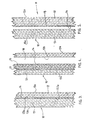
- the transparent or translucent panel portion 10 is provided according to the arrangement of figure 2 which shows the panel 10 in cross-section.
- an inner face sheet 12 of the panel 10 is provided by a sheet of high temperature and thermal shock resistant material such as clear glass material (such as is known in the trade as "Vycor” brand 96% silica glass) which has a high temperature resistance to thermal shock.
- Another surface sheet 13 of the panel 10 is also preferably provided in a high temperature resistance material but which may have a thermal resistance somewhat less than the material forming the inner sheet 12 a material such as tempered glass.
- the arrangement allows the outer sheet 13 to have a higher mechanical impact strength than inner sheet 12 as glass materials with high temperature ratings usually have relatively low mechanical impact strengths.
- the transparent or translucent panel 10 is thus able to withstand high temperatures adjacent the inner face 12a and yet have mechanical impact strength to guard against damage in use such as being accidentally bumped or kicked.
- an outer surface 13b of the outer sheet 13 is reflectorised, for example by the deposit, such as by vacuum deposit, metal spraying or depositing by electrical means, particles, spots or strips of one or more reflector materials such as chromium, aluminium, or a metal alloy or oxide on to the inner surface 13b to thus provide at least partial reflectorisation of said panel 10 to reflect some radiant heat originating from the fuel in the cavity 7 back into the fire cavity 7.
- the deposit such as by vacuum deposit, metal spraying or depositing by electrical means, particles, spots or strips of one or more reflector materials such as chromium, aluminium, or a metal alloy or oxide on to the inner surface 13b to thus provide at least partial reflectorisation of said panel 10 to reflect some radiant heat originating from the fuel in the cavity 7 back into the fire cavity 7.
- the reflectivity is preferably up to approximately 75t of the radiant heat to which it is exposed to from an interior of the fire chamber.
- this is in no way limiting and it will be appreciated that the extent of reflectorisation can be varied to suit use conditions and heater constructions.
- the preferred embodiment of the invention provides for the reflectorisation to be provided to a level whereby a person viewing the transparent or translucent portion from the outside when the fire is in operation, the flame is readily visible yet when the apparatus is not in operation the reflectorisation prevents the person readily seeing into the fire chamber.
- the reflectorisation is provided in the form of screen matrix or plurality of disbursed particles mounted adjacent, applied to or embedded in or below the surface of the portions forming the transparent or translucent panel 10.
- the reflectorisation can be provided as a thin metal or oxide deposit sufficient to achieve the desired extent of reflectorisation.
- a normal running temperature of the inner surface 12a is above the normal condensing temperature of creosote and other combustion products which cause staining or other obscuration of the inner surface 12a. It will also be appreciated that the high surface temperature will burn off any deposits occurring during a lighting phase, or before the unit has achieved a stable normal operation.
- a normal running temperature at which the inner surface 12a operates is effectively able to be controlled by the extent of insulation which is applied to the remaining portions of the fire chamber assembly 2 (other than the transparent or translucent panel 10) and the extent of reflectorisation in the panel 10 together with the air supply and fuel combustion rate.
- the invention has been described with reference to the sandwiching of the reflectorisation between sheets forming the transparent or translucent panel 10; that is between the inner and outer sheets 12 and,13. this has the effect of protecting the reflectorisation from mechanical damage.
- the reflectorisation can be provided on or adjacent the inner or outer surfaces 12a, 12b or 13a.
- the reflectorisation 14 can be provided either by a coating applied to one or other of the opposing adjacent surfaces of the sheets 12 or 13 or alternatively, by the installation of a screen matrix or other element such as perforated metal sheet or foil providing the at least partial reflectorisation between the opposing surfaces of the inner and outer sheets 12 and 13.
- this assembly shows the panel 10 reflectorised at 14 on an inwardly facing surface 16 of a mid panel 17 with a cavity 18 defined between the reflectorisation 14 and surface 12b of the inner panel 12.
- the additional insulation provided by the cavity 18 further facilitates the maintenance of the inner surface 12a at high temperatures during use to avoid . condensation of combustion products and the outer surface 13a at lower temperatures.
- the reflectorisation is shown to be provided as treatment particles or a screen matrix embedded in a portion of the inner sheet 12 such as during formation of the inner sheet 12.
- the reflectorisation 14 can also be provided in the sheet 13.
- reflectorisation is described in this form of the invention as being in the form of a substantially mirrored surface using materials such as chromium, nickel, aluminium or metal alloy or oxide treatments, it will be appreciated that in alternative forms of the invention, other reflectorisation materials may be utilised such as those where the proportion of the incident radiant heat reflected varies in respect of certain radiant heat wavelengths to enable selective reflection of radiant heat back into the cavity 7; materials such as particles, screens, sheets, films, layers and the like having reflective properties.
- the reflectorisation of the embodiments of figures 2, 3 and 4 are not necessarily mounted on a "surface" of the transparent or translucent panel 10 and are alternatively self supporting or otherwise supported for positioning adjacent elements forming the transparent or translucent panel 10.
- the transparent or translucent portion 10 can be provided in a single panel when the panel 10 is treated so as to provide the reflectorisation.
- This arrangement is particularly suited where the reflectorisation is either protected by being embedded in the sheet material, such as as has been described with reference to Figure 5 or alternatively, where the reflectorisation is sufficiently robust to withstand the rigours of use. It is preferred, although not essential, that the reflectorisation in this arrangement be provided either on or adjacent the innermost surface of the transparent or translucent portion 10 however, in an alternative embodiment of this form of the invention, .the reflectorisation can be provided at or near an outer surface of the transparent or translucent panel portion however, this is less effective than the arrangement described hereinbefore.
Landscapes
- Engineering & Computer Science (AREA)
- Chemical & Material Sciences (AREA)
- Combustion & Propulsion (AREA)
- Mechanical Engineering (AREA)
- General Engineering & Computer Science (AREA)
- Baking, Grill, Roasting (AREA)
- Resistance Heating (AREA)
- Yarns And Mechanical Finishing Of Yarns Or Ropes (AREA)
- Electric Stoves And Ranges (AREA)
- Glass Compositions (AREA)
Applications Claiming Priority (2)
| Application Number | Priority Date | Filing Date | Title |
|---|---|---|---|
| NZ210367A NZ210367A (en) | 1984-11-28 | 1984-11-28 | Solid fuel stove with transparent or translucent portion in fire chamber |
| NZ210367 | 1984-11-28 |
Publications (2)
| Publication Number | Publication Date |
|---|---|
| EP0183559A2 true EP0183559A2 (fr) | 1986-06-04 |
| EP0183559A3 EP0183559A3 (fr) | 1987-05-20 |
Family
ID=19921001
Family Applications (1)
| Application Number | Title | Priority Date | Filing Date |
|---|---|---|---|
| EP85308691A Withdrawn EP0183559A3 (fr) | 1984-11-28 | 1985-11-28 | Appareil de chauffage |
Country Status (6)
| Country | Link |
|---|---|
| US (1) | US4667607A (fr) |
| EP (1) | EP0183559A3 (fr) |
| AU (1) | AU596349B2 (fr) |
| CA (1) | CA1254123A (fr) |
| NO (1) | NO854773L (fr) |
| NZ (1) | NZ210367A (fr) |
Cited By (5)
| Publication number | Priority date | Publication date | Assignee | Title |
|---|---|---|---|---|
| FR2617270A1 (fr) * | 1987-06-23 | 1988-12-30 | Supra Sa | Foyer ferme a haute temperature a feu visible ou non, en particulier du type foyer de cheminee ou poele |
| EP0299935A1 (fr) * | 1987-07-17 | 1989-01-18 | Saes Getters S.P.A. | Fenêtre de four ménager comportant une surface extérieure à température basse |
| FR2623881A1 (fr) * | 1987-11-27 | 1989-06-02 | Supra Sa | Foyer de cheminee ou poele de type buches a gaz |
| FR2639097A1 (fr) * | 1988-11-17 | 1990-05-18 | Bourgeois Ste Coop Production | Four a porte double |
| EP1455139A3 (fr) * | 2003-03-05 | 2007-06-27 | Lohberger, Heiz + Kochgeräte-Technologie GmbH | Regard pour un poêle |
Families Citing this family (8)
| Publication number | Priority date | Publication date | Assignee | Title |
|---|---|---|---|---|
| AT1154U1 (de) * | 1995-12-19 | 1996-11-25 | Pfisterer Kurt | Verschlusseinrichtung für ofenöffnungen |
| US5797736A (en) * | 1996-12-03 | 1998-08-25 | University Of Kentucky Research Foundation | Radiation modulator system |
| US20050066960A1 (en) * | 2003-09-30 | 2005-03-31 | Harp Debra L. | Firelight reflective system and method |
| FR2873791B1 (fr) * | 2004-07-30 | 2006-11-03 | Eurokera | Plaque en materiau verrier pour dispositif de type insert de cheminee ou poele. |
| GB2423463B (en) * | 2005-07-09 | 2007-02-07 | Richards Morphy N I Ltd | Kitchen appliance |
| FR2937405B1 (fr) * | 2008-10-16 | 2010-11-26 | Fondis Sa | Fourreau d'isolation thermique pour l'habillage decoratif d'une facade d'un ensemble renfermant un appareil de chauffage avec vision des flammes. |
| TWI645783B (zh) * | 2017-12-27 | 2019-01-01 | 國家中山科學研究院 | Kiln oven |
| DE102019102559B4 (de) * | 2019-02-01 | 2024-02-22 | Schott Ag | Kaminofen |
Family Cites Families (6)
| Publication number | Priority date | Publication date | Assignee | Title |
|---|---|---|---|---|
| BE794981A (fr) * | 1972-02-05 | 1973-05-29 | Jega Friedrichsthaler Eisen | Four a cuire et a frire |
| US4048978A (en) * | 1972-03-02 | 1977-09-20 | Glaverbel-Mecaniver | Heat insulating screen |
| US4084571A (en) * | 1976-09-20 | 1978-04-18 | The Tappan Company | See-through oven door with reticulated heat shield |
| JPS54103174A (en) * | 1978-01-31 | 1979-08-14 | Tokyo Shibaura Electric Co | Cooking instrument |
| DE2929473A1 (de) * | 1978-08-31 | 1980-03-06 | Atag Bv Apparatenfab | Haushaltofen |
| US4382177A (en) * | 1980-09-15 | 1983-05-03 | Heaney James J | Substantially transparent insulating anti-condensation structure |
-
1984
- 1984-11-28 NZ NZ210367A patent/NZ210367A/xx unknown
-
1985
- 1985-11-28 CA CA000496371A patent/CA1254123A/fr not_active Expired
- 1985-11-28 NO NO854773A patent/NO854773L/no unknown
- 1985-11-28 AU AU50490/85A patent/AU596349B2/en not_active Ceased
- 1985-11-28 EP EP85308691A patent/EP0183559A3/fr not_active Withdrawn
- 1985-11-29 US US06/802,822 patent/US4667607A/en not_active Expired - Fee Related
Cited By (7)
| Publication number | Priority date | Publication date | Assignee | Title |
|---|---|---|---|---|
| FR2617270A1 (fr) * | 1987-06-23 | 1988-12-30 | Supra Sa | Foyer ferme a haute temperature a feu visible ou non, en particulier du type foyer de cheminee ou poele |
| EP0299935A1 (fr) * | 1987-07-17 | 1989-01-18 | Saes Getters S.P.A. | Fenêtre de four ménager comportant une surface extérieure à température basse |
| FR2623881A1 (fr) * | 1987-11-27 | 1989-06-02 | Supra Sa | Foyer de cheminee ou poele de type buches a gaz |
| FR2639097A1 (fr) * | 1988-11-17 | 1990-05-18 | Bourgeois Ste Coop Production | Four a porte double |
| EP0369905A1 (fr) * | 1988-11-17 | 1990-05-23 | SOCIETE COOPERATIVE DE PRODUCTION BOURGEOIS (Société Coopérative de Production Anonyme à Capital Variable) | Four à porte double |
| US5022380A (en) * | 1988-11-17 | 1991-06-11 | Societe Cooperative De Production Bourgeois | Oven with double door |
| EP1455139A3 (fr) * | 2003-03-05 | 2007-06-27 | Lohberger, Heiz + Kochgeräte-Technologie GmbH | Regard pour un poêle |
Also Published As
| Publication number | Publication date |
|---|---|
| NZ210367A (en) | 1988-08-30 |
| AU596349B2 (en) | 1990-05-03 |
| EP0183559A3 (fr) | 1987-05-20 |
| AU5049085A (en) | 1986-06-05 |
| CA1254123A (fr) | 1989-05-16 |
| NO854773L (no) | 1986-05-29 |
| US4667607A (en) | 1987-05-26 |
Similar Documents
| Publication | Publication Date | Title |
|---|---|---|
| US4667607A (en) | Heating | |
| US4817585A (en) | Firebox door arrangement | |
| US4805588A (en) | Over and under radiant broiler oven | |
| US3422809A (en) | Self-cleaning oven | |
| US4305373A (en) | Fireplace furnace | |
| JP2003322330A (ja) | 燃焼装置窓用材料 | |
| US5471973A (en) | Direct vent fireplace | |
| US4191162A (en) | Energy saving air-flow heater | |
| CN1200221C (zh) | 燃气烤炉的烤箱加热装置 | |
| JP7360337B2 (ja) | 電気式ピザ窯 | |
| US2133184A (en) | Combination coal-wood electric range | |
| WO1985004464A1 (fr) | Cheminee et procede pour bruler des combustibles dans des cheminees | |
| US6125837A (en) | Grill | |
| US7069925B2 (en) | Pressure relief system for a gas fireplace | |
| CA1127031A (fr) | Ecran en verre a rideau d'air pour foyers et poeles a bois | |
| CA2464061A1 (fr) | Foyer a gaz exterieur | |
| CA3112155A1 (fr) | Echangeur de chaleur a barriere de securite | |
| CN100441955C (zh) | 具有烘焦装置的微波炉 | |
| US20100242947A1 (en) | Locked cartridge fireplace firebox | |
| EP1116919A2 (fr) | Cheminée à étagère chauffante | |
| JP3005845B2 (ja) | グリル庫の排気構造 | |
| JPS61110829A (ja) | 調理用排気装置 | |
| US4274393A (en) | Fireplace assembly | |
| CN2412082Y (zh) | 防火门 | |
| KR940001032Y1 (ko) | 구이용 버너가 설치되는 식탁의 열 차단장치 |
Legal Events
| Date | Code | Title | Description |
|---|---|---|---|
| PUAI | Public reference made under article 153(3) epc to a published international application that has entered the european phase |
Free format text: ORIGINAL CODE: 0009012 |
|
| AK | Designated contracting states |
Kind code of ref document: A2 Designated state(s): AT BE CH DE FR GB IT LI LU NL SE |
|
| PUAL | Search report despatched |
Free format text: ORIGINAL CODE: 0009013 |
|
| AK | Designated contracting states |
Kind code of ref document: A3 Designated state(s): AT BE CH DE FR GB IT LI LU NL SE |
|
| 17P | Request for examination filed |
Effective date: 19870717 |
|
| 17Q | First examination report despatched |
Effective date: 19880610 |
|
| STAA | Information on the status of an ep patent application or granted ep patent |
Free format text: STATUS: THE APPLICATION IS DEEMED TO BE WITHDRAWN |
|
| 18D | Application deemed to be withdrawn |
Effective date: 19900220 |
|
| RIN1 | Information on inventor provided before grant (corrected) |
Inventor name: FLEMMING, JOHN STUART |