EP0183568B1 - Garde-temps électronique à jauge de profondeur - Google Patents
Garde-temps électronique à jauge de profondeur Download PDFInfo
- Publication number
- EP0183568B1 EP0183568B1 EP85308756A EP85308756A EP0183568B1 EP 0183568 B1 EP0183568 B1 EP 0183568B1 EP 85308756 A EP85308756 A EP 85308756A EP 85308756 A EP85308756 A EP 85308756A EP 0183568 B1 EP0183568 B1 EP 0183568B1
- Authority
- EP
- European Patent Office
- Prior art keywords
- signal
- circuit
- depth
- water
- water depth
- Prior art date
- Legal status (The legal status is an assumption and is not a legal conclusion. Google has not performed a legal analysis and makes no representation as to the accuracy of the status listed.)
- Expired
Links
Images


Classifications
-
- G—PHYSICS
- G04—HOROLOGY
- G04G—ELECTRONIC TIME-PIECES
- G04G21/00—Input or output devices integrated in time-pieces
- G04G21/02—Detectors of external physical values, e.g. temperature
-
- G—PHYSICS
- G04—HOROLOGY
- G04C—ELECTROMECHANICAL CLOCKS OR WATCHES
- G04C10/00—Arrangements of electric power supplies in time-pieces
- G04C10/04—Arrangements of electric power supplies in time-pieces with means for indicating the condition of the power supply
-
- B—PERFORMING OPERATIONS; TRANSPORTING
- B63—SHIPS OR OTHER WATERBORNE VESSELS; RELATED EQUIPMENT
- B63C—LAUNCHING, HAULING-OUT, OR DRY-DOCKING OF VESSELS; LIFE-SAVING IN WATER; EQUIPMENT FOR DWELLING OR WORKING UNDER WATER; MEANS FOR SALVAGING OR SEARCHING FOR UNDERWATER OBJECTS
- B63C11/00—Equipment for dwelling or working underwater; Means for searching for underwater objects
- B63C11/02—Divers' equipment
- B63C2011/021—Diving computers, i.e. portable computers specially adapted for divers, e.g. wrist worn, watertight electronic devices for detecting or calculating scuba diving parameters
Definitions
- the present invention relates to an electronic timepiece with a depth gauge.
- a depth gauge circuit is arranged as an additional function in a conventional electronic watch with a depth gauge which comprises a timepiece circuit, a display unit and a battery.
- the display unit and the battery are used in both time and depth display modes, and these modes are selectively performed upon switching.
- the timepiece circuit and the depth gauge circuit are selectively used while the battery and the display unit are always used to perform time or depth display. For example, even when the battery voltage drops to disable normal operation of the depth gauge circuit, the depth gauge circuit is operated and displays an incorrect water depth which differs from the actual water depth. in this case, a user or diver believes the wrong depth displayed on his watch and continues to dive, endangering his life.
- external operation members pushbuttons or the like
- the waterproof property of the watch is degraded upon operation of the external operation members, and water may enter inside the watch.
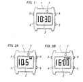
- Fig. 1 shows an electronic timepiece with a depth gauge in the timepiece mode
- Figs. 2A and 2B respectively show a water depth display mode and a dive time display mode.
- reference numeral 1 denotes an electronic timepiece with a depth gauge; 2, a display unit; 3, a mode selection button; and 4 and 5, select and set buttons for correcting time and setting timer time.
- the select button 4 is fitted in the case to prevent an erroneous operation.
- Reference numeral 6 denotes a lamp button; and 7, a water pressure sensor.
- Fig. 1 shows a timepiece display state, showing 10:30, in this case.
- Fig. 2A shows a water depth display state, actually showing 10.5 meters
- Fig. 2B shows a dive timer display state, actually showing an allowable remaining time, i.e., 16 minutes.
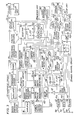
- Fig. 3 is a block diagram of the electronic timepiece shown in Fig. 1.
- Reference numeral 51 denotes a timepiece circuit which has an oscillator 10, a frequency divider 11 and a timer 12. An oscillation signal from the oscillator 10 is supplied to the frequency divider 11, and the frequency divider 11 generates frequency-divided signals f0 and ft. The timer 12 is started in response to the frequency-divided signal ft and generates a time information signal P1.
- Reference numeral 13 denotes a display switching circuit, an input terminal A of which receives the time information signal P1 and an input terminal B of which receives an additional function information signal P5 from an additional function information switching circuit 70 (to be described in detail below).
- the additional function information switching circuit 70 When a control terminal C of the circuit 70 is set at level "H” in response to a control signal PC1 to be described later, the additional function information switching circuit 70 generates the time information signal P1 as a display information signal P2. However, when the control terminal C of the circuit 70 is set at level "L", the circuit 70 generates the additional function information signal P5 as the display information signal P2.
- Reference numeral 14 denotes a decoder which receives the display information signal P2 to cause the display unit 2 to perform time display (Fig. 1) or water depth/dive timer display (Fig. 2A/ 2B).
- Reference numerals 3a, 4a, 5a and 6a denote switches controlled by operation buttons 3, 4, 5 and 6 of Fig. 1, respectively. More particularly, the switch 3a serves as a mode selection switch; 4a, a selection switch; 5a, a set switch; and 6a, a lamp switch.
- Reference numerals 40, 41 and 42 denote pulsers, respectively.
- the pulser 40 pulsates an operation signal from the mode selection switch 3a and generates a mode selection signal PM.
- the pulsers 41 and 42 pulsate operation signals from the switches 4a and 5a and generate a selection signal PSL and a set signal PST, respectively.
- Reference numeral 39 denotes a mode control circuit which comprises a ternary shift register with three output terminals Q1, Q2 and Q3.
- the output terminals Q1, Q2 and Q3 are sequentially selected in response to the mode selection signal PM supplied to a clock terminal (p of the mode control circuit 39, as indicated by the solid lines.
- the output terminal Q1 of the mode control circuit 39 is forcibly reset in response to a signal supplied to a reset terminal R thereof.
- the mode control circuit 39 When the output terminal Q1 of the mode control circuit 39 is specified, the mode control circuit 39 generates a timepiece function designation signal PC1. When the output terminal Q2 is specified, the circuit 39 generates a dive timer designation signal PC2. When the output terminal Q3 is specified, the circuit 39 generates a water depth designation signal PC3.
- Reference numeral 7 denotes a water pressure sensor shown in Fig. 1. The water pressure sensor 7 comprises a diaphragm type semiconductor pressure sensor for detecting a water pressure and generating an electrical sensor signal PP.
- Reference numeral 17 denotes a depth gauge circuit which comprises an amplifier 18, a water pressure measuring circuit 19, a water depth detector 20 and an initial value setting circuit 21.
- the amplifier 18 amplifies the sensor signal PP, and an amplified signal is supplied to the water pressure measuring circuit 19.
- the water pressure measuring circuit 19 converts the analog sensor signal PP to a digital signal and a water depth information signal P3.
- the timepiece function designation signal PC1 is inverted by an inverter 61, and an inverted signal PC1 is delayed by a delay circuit 62 for a predetermined period of time. The delayed signal is supplied to a trigger terminal T of the initial value setting circuit 21, thereby causing initialization of the setting circuit 21 in the following manner.
- a variable resistor is arranged in the amplifier 18 in the depth gauge circuit 17 to adjust an offset value in the conventional electronic watch with a pressure gauge.
- the resistance of the variable resistor is adjusted by an external operation member such as a crown to display a water surface pressure to be zero in the conventional electronic watch with a depth gauge.
- an offset caused by use at different atmospheric pressures or by different temperature conditions of the pressure sensor can be automatically adjusted. Therefore, pressure changes caused by only water pressures can be extracted as the water depth information signal P3.
- the water depth detector 20 receives the water depth information signal P3 from the water pressure measuring circuit 19 and performs preset water depth detection. The water depth detector 20 then generates a first water depth detection signal PK1 representing a depth range of 0 to 1 meter, i.e., a nondiving state, and a second water depth detection signal PK2 representing a depth range of 30 to 40 meters or more, i.e., a deep, dark underwater state from the output terminals Q1 and Q2 thereof.
- PK1 representing a depth range of 0 to 1 meter
- PK2 representing a depth range of 30 to 40 meters or more, i.e., a deep, dark underwater state
- Reference numeral 63 denotes a power supply control circuit which is enabled in response to only the inverted signal PC1 of the timepiece function designation signal PC1.
- the power supply control circuit 63 supplies a power supply voltage to a power supply terminal Vdd of the depth gauge circuit 17.
- Reference numeral 60 denotes a water pressure switch circuit which comprises a rapid change detector 64 and a switch timer 65.
- the rapid change detector 64 receives the water depth information signal P3 from the water pressure measuring circuit 19 and is operated in response to a rapid pressure change due to normal diving.
- the rapid change detector 64 generates a water pressure rapid change pulse signal PKS.
- the switch timer 65 is operated in response to the water pressure rapid change signal PSK from the rapid change detector 64 and generates a switch signal PS with a predetermined duration at the output terminal Q thereof.
- Reference numeral 25 denotes a waste time detector.
- a reset terminal R of the detector 25 receives through an OR gate 67 a signal PK1 obtained by inverting the first water depth detection signal PK1 from the water depth detector 20 by an inverter 66.
- the reset terminal R of the detector 25 also receives the timepiece function designation signal PC1 from the mode control circuit 39 through an OR gate 67.
- a clock terminal ⁇ p of the waste time detector 25 receives the frequency-divided signal f0 from the frequency divider 11.
- the waste time detector 25 counts the inverted signal PK1 of level "L” and the timepiece function designation signal PC1 of level “L” in response to the clock signal f0. When a predetermined period of time (10 minutes in this embodiment) has elapsed, the waste time detector 25 generates a time up signal PZ.
- Reference numeral 54 denotes a dive timer which comprises a pulser 56, a T-FF 55 and a timer function circuit 27.
- the pulser 56 receives the first water depth detection signal PK1 from the water depth detector 20 and generates pulses respectively at the leading and trailing edges of the first water depth detection signal PK1.
- the T-FF 55 receives the pulse signal from the pulser 56 and performs inversion operation, thereby generating a timer control signal PT.
- the timepiece function designation signal PC1 is supplied to the reset terminal R of the T-FF 55, so that the T-FF 55 is rendered inoperative in the timepiece mode.
- the timer function circuit 27 comprises a timer circuit which is operated in response to the timer control signal PT supplied to a count control terminal CE thereof.
- the timer function circuit 27 generates the timer operation time information as a timer information signal P4 from an output terminal Q thereof in response to the selection signal PSL supplied to a selection terminal SL thereof and the set signal PST supplied to a set terminal ST thereof.
- the timer function circuit 27 also performs a subtraction in response to the clock signal f0 supplied to a clock terminal (p thereof and generates a time up signal PB from its output terminal B when the subtraction is completed.
- Reference numeral 28 denotes a buzzer unit which comprises a driver 29 and a buzzer 30.
- the driver 29 operates the buzzer 30 for a predetermined period of time, thereby signalling to the diver that the time is up.
- Reference numeral 70 denotes an additional function information switching circuit which comprises a selector 71, a T-FF 72 with set and reset terminals, AND gates 73, 74 and 75, and an inverter 76.
- the water depth information signal P3 is supplied from the water pressure measuring circuit 19 to an input terminal A of the selector 71.
- the timer information signal P4 is supplied from the timer function circuit 27 to an input terminal B of the selector 71.
- a control terminal C of the selector 71 is set at level "H"
- the water depth information signal P3 supplied to the input terminal A is selected as an additional function information signal P5 which appears at its output terminal Q.
- the control terminal C is set at level "L”
- the timer information signal P4 supplied to the input terminal B appears as the additional function information signal P5.
- the T-FF 72 comprises a T-FF with set/reset priority.
- a set terminal S of the T-FF 72 When a set terminal S of the T-FF 72 is set at level "H”, its output terminal Q is set at level "H". However, when a reset terminal R is set at level "H”, the output terminal Q is forcibly compulsorily set at level "L”. Only when the set and reset terminals S and R are both set at level "L", the output terminal Q is inverted for every signal input to a toggle terminal T of the T-FF 72.
- An output signal from the output terminal Q of the T-FF 72 is supplied as a switching control signal PC4 to the control terminal C of the selector 71.
- the AND gates 73 and 74 are enabled when the first water depth detection signal PK1 from the water depth detector 20 is set at level "H”.
- the AND gate 75 is enabled when the first water depth detection signal PK1 is set at level "L”.
- the water depth designation signal PC3, the dive timer designation signal PC2 and the rapid change detection signal PKS are supplied to the set terminal S, the reset terminal R and the toggle terminal T, respectively, of the T-FF 72.
- the additional function information switching circuit 70 is operated as follows. In the water depth gauge mode, when the first water depth detection signal PK1 is generated by the water depth detector 20, that is, when diving is not performed, the AND gate 73 is enabled. The selector 71 controlled in response to the output from the T-FF 72 is switched in response to the water depth designation signal PC3 and the dive timer designation signal PC2 which are generated by the mode control circuit 39. When the water depth detection signal PK1 is not generated, that is, while diving is being performed, the AND gate 75 is enabled. The additional function information switching circuit 70 is switched in response to the water pressure rapid change signal PSK from the water pressure switch circuit 60.
- Reference numeral 31 denotes a lamp control circuit which comprises AND gates 32, 33 and 34 and an OR gate 35.
- the second water depth detection signal PK2 from the water depth detection circuit 20 is supplied to the first input terminals of the AND gates 32, 33 and 34, and the switch signal PS from the switch timer 65 in the water pressure switch circuit 60, the set signal PST as the operation signal from the set switch 5a, and the mode selection signal PM as the operation signal from the mode selection switch 3a are supplied to the second input terminals of the AND gates 32, 33 and 34, respectively.
- Four input terminals of the OR gate 35 are connected to the output terminals of the AND gates 32, 33 and 34 and the lamp switch 6a.
- a lamp ON signal PLD appears at the output terminal of the OR gate 35.
- Reference numeral 36 denotes a lamp unit which comprises a driver 37 and a lamp 38.
- the lamp ON signal PLD from the lamp control circuit 31 causes the lamp 38 to turn on to drive the display unit 2.
- the lamp control circuit 31 causes the lamp 38 to turn on in response to only the lamp ON signal PLD.
- the AND gates 32, 33 and 34 are enabled, so that all lamp ON signals PLD generated upon operations of the mode selection switch 3a, the set switch 5a and the water pressure switch signal PLD can drive the lamp 38.
- Reference numeral 48 denotes a battery voltage detector which generates a voltage drop detection signal PBD upon detection of a voltage drop of a battery BT.
- the voltage drop detection signal PBD is supplied to the reset terminal R of the mode control circuit 39 through the OR gate 68.
- the output terminal Q1 of the mode control circuit 39 is specified, and the timepiece function designation signal PC1 is generated.
- the display switching circuit 13 generates as the display information signal P2 the time information signal P1 supplied to the input terminal A thereof.
- the time information signal P1 is supplied to the display unit 2 through the decoder 14, so that time 10:30 is displayed on the display unit 2, as shown in Fig. 1.
- the dive timer 54 and the waste time detector 25 are reset in response to the timepiece function designation signal PC1 and are rendered inoperative.
- the power supply control circuit 63 is disabled in response to the inverted signal PC1. As a result, the depth gauge circuit 17 is deenergized.
- the user can operate the selection button 4 and the set button 5 to correct time information displayed on the display unit 2 in accordance with a known method.
- the above description is concerned with the operation of the electronic watch in the timepiece mode.
- the operations of the electronic timepiece in the dive mode will be described below.
- the timepiece mode is switched to the dive mode upon operation of the mode selection button 3.
- the output terminal Q2 of the mode control circuit 39 is switched in response to the mode selection signal PM supplied to the clock terminal cp, as indicated by the solid arrow.
- the mode control circuit 39 thus generates the dive timer designation signal PC2.
- the timepiece function designation signal PC1 is inverted to level "L”
- the display switching circuit 13 is switched to a selection state represented by the additional function information signal P5 supplied to the input terminal B thereof.
- the reset status of the waste time detector 25 is released, and the detector 25 starts counting time in response to the clock signal f0.
- the reset status of the dive timer 54 is released, so that it is held in the ready state.
- the power supply control circuit 63 When the inverted signal PC1 goes to level "H", the power supply control circuit 63 is started to supply power to the depth gauge circuit 17. In this state, the depth gauge circuit 17 starts measuring the water pressure in accordance with the sensor signal PP from the water pressure sensor 7. Upon operation of the power supply control circuit 63, the delay circuit 62 is also operated. When a predetermined period of time (60 seconds in this embodiment) has elapsed, the delay circuit 62 supplies the initialization signal PV to the initial value setting circuit 21. The initial value is set in the depth gauge circuit 17, and water pressure measurement is started. However, in this state, the diver has not dived yet, so that the first and second water depth detection signals PK1 and PK2 from the water depth detector 20 are respectively set at level “H” and level "L".
- the T-FF 72 in the additional function information switching circuit 70 is forcibly reset to disable the switching control signal PC4.
- the selector 71 is set in a state to select the timer information signal P4 supplied to the input terminal B thereof.
- the timer information signal P4 is displayed on the display unit 2 through the additional function information switching circuit 70 and the display switching circuit 13, as shown in Fig. 2B.
- the diver operates the selection button 4 and the set button 5 while he visually checks the dive display content.
- the timer time required for the timer function circuit 27 can be set.
- the output terminal Q3 of the mode control circuit 39 is specified, so that the depth gauge designation signal PC3 is generated.
- the dive timer designation signal PC2 at the output terminal Q2 disappears, so that the T-FF 72 in the additional function information switching circuit 70 is set and the switching control signal PC4 is set at level "H".
- the selector 71 is set in the state to select the water depth information signal P3 supplied to the input terminal A thereof.
- the water depth information signal P3 is supplied to the display unit 2 through the additional function information switching circuit 70 and the display switching circuit 13, so that a water depth is displayed as shown in Fig. 2B.
- the diving operation will be described wherein a user carries the electronic timepiece 1 set in the dive mode upon a series of operations and is going to dive.
- the water depth information signal P3 from the depth gauge circuit 17 represents 0 meter upon the initialization described above.
- the first water depth detection signal PK1 from the water depth detector 20 is set at level "H".
- the water depth detector 20 detects the water depth information signal P3, and the first water depth detection signal PK1 goes to level “L".
- the waste time detector 25 is reset again in response to level "H” of the signal PK1 inverted by the inverter 66.
- the count of the waste time detector 20 is cleared.
- the output from the T-FF 55 in the dive timer 54 is inverted in response to the pulse from theactuer56 upon inversion of the first water depth detection signal PK1.
- the timer control signal PT is supplied to the countcontrol circuit CE, so that the timer function circuit 27 starts decrementation of the timer time.
- the AND gate 75 is enabled through the inverter 76 while the AND gates 73 and 74 are kept off, and compulsory designation mode of display switching synchronized with the dive timer designation signal PC2 and the water depth designation signal PC3 from the mode control circuit 39 is inhibited.
- the T-FF72 performs inversion switching in response to the water pressure rapid change signal PKS supplied by the water pressure switch circuit 60 to the toggle terminal T through the AND gate 75.
- the diver During the dive at a depth of 1 meter or more, the diver rapidly moves his hand with the electronic timepiece 1, and a rapidly changing pressure is applied to the water pressure sensor 7.
- the depth gauge and dive timer display modes of the display unit 2 can be alternately set. Therefore, the diver need not depress the buttons to arbitrarily set the depth gauge or dive timer display mode.
- the water depth detection circuit 20 detects the water depth information signal P3 and generates the second water depth detection signal PK2. All the AND gates 32, 33 and 34 in the lamp control circuit 31 are turned on by the signal PK2. All the lamp button 6, the mode selection button 3 and the set button 5 have the lamp ON function. Therefore, the lamp 38 is turned on for a timewidth of the switch signal PS upon operation of the water pressure switch 60.
- the lamp 38 is turned on upon operation of the water pressure switch circuit 60, thereby eliminating manual operation of the lamp button 6.
- the diver can depress any of the buttons to turn on the lamp 38.
- the time up signal PB appears at the output terminal B of the timer function circuit 27, and an alarm sound is generated by the buzzer unit 28.
- the diver starts to ascend to the water surface in response to the alarm sound.
- the second water depth detection signal PK 2 is no longer generated by the water depth detector 20, thereby rendering the lamp control circuit 31 inoperative.
- the water depth detector 20 generates the first water depth detection signal PK1 again.
- the T-FF 55 in the dive timer 54 is inverted, so that the dive timer 54 is set in the ready state.
- the additional function information switching circuit 70 restores the compulsory designation mode.
- the reset state of the waste time detector 25 is cancelled in response to the inverted signal PK1 from the inverter 66.
- the waste time detector 25 starts counting the time.
- the time up signal PZ is generated by the waste time detector25 to reset the mode control circuit 39 through the OR gate 68.
- the output terminal Q1 of the mode control circuit 39 is forcibly specified, as indicated by the broken arrow of Fig. 3.
- the timepiece function designation signal PC1 is generated by the mode control circuit 39, thereby restoring the timepiece mode of Fig. 1.
- the restoration operation of the waste time detector 25 to the timepiece function prevents wasteful current consumption of the depth gauge circuit 17 when the depth gauge mode is accessed upon erroneous depression of the mode selection button 3 or when the diver forgets to cancel the depth gauge mode after diving is completed.
- the diver notices thatthe depth gauge mode is kept set after diving, he depresses the mode selection button 3 to manually restore the initial state of the mode selection circuit 39, thereby preventing wasteful current consumption.
- the above description exemplifies the normal operation when the voltage at the battery BT is sufficiently high. The operation of the electronic timepiece will be described wherein the battery BT is almost dead.
- the battery voltage detector 48 detects a voltage drop and generates a voltage drop detection signal PBD.
- the signal PBD is supplied to the mode control circuit 39 through the OR gate 68, so that the circuit 39 is kept reset.
- the mode control circuit 39 When the voltage drop detection signal PBD is generated, the mode control circuit 39 is forcibly held in the timepiece mode.
- the depth gauge mode as the additional function cannot be set.
- the depth gauge function is inhibited in an unstable state, which may endanger diver's life, where the battery voltage is deceased, thereby improving reliability of the electronic timepiece as a measuring instrument.
- Fig. 4 is a block diagram of an electronic timepiece with a depth gauge according to another embodiment of the present invention.
- the basic system configuration of the electronic timepiece of this embodiment is substantially the same as that of the previous embodiment, except that a photoswitch circuit 80 is used in place of the water pressure switch circuit 60 and a photosensor 8 is arranged to supply a photo input signal PIH to the photoswitch circuit 80.
- the photosensor 8 is arranged at a position where external light incident on an electronic watch 1 can be detected (to be described in detail later).
- the photoswitch circuit 80 comprises a photodetector 81 for generating the photo input signal PIH as a photo rapid change pulse signal PKH and a switch timer 82 for receiving the photo rapid change signal PKH and generating a switch signal PS with a predetermined duration at its output terminal Q.
- the control function obtained by the photo rapid change signal PKH and the switch signal PS is the same as that obtained by the water pressure rapid change signal PKS and the switch signal PS in Fig. 3.
- Fig. 5 is a perspective view showing a photo input state of the electronic timepiece 1 of Fig. 4.
- An underwater light 9 is turned on to emit light toward the photosensor 8 arranged below the display unit 2, thereby selectively setting the dive timer display mode of Fig. 2B or the depth gauge display mode of Fig. 2A.
- the timepiece mode is not switched to the depth gauge mode, thereby inhibiting use of the timepiece as the depth gauge while the depth gauge circuit is not normally operating. Safety of diver's life is guaranteed. Furthermore, underwater display mode switching and lamp ON operation can be performed without touching the water pressure switch or the photoswitch. In this manner, underwater button operation which may cause water to enter inside the watch housing need not be performed. Therefore, a highly reliable electronic watch with a depth gauge can be achieved.
Landscapes
- Physics & Mathematics (AREA)
- General Physics & Mathematics (AREA)
- Engineering & Computer Science (AREA)
- Power Engineering (AREA)
- Electric Clocks (AREA)
Claims (9)
Applications Claiming Priority (10)
| Application Number | Priority Date | Filing Date | Title |
|---|---|---|---|
| JP252871/84 | 1984-11-30 | ||
| JP252872/84 | 1984-11-30 | ||
| JP59252870A JPS61130888A (ja) | 1984-11-30 | 1984-11-30 | 水深計付電子時計 |
| JP252870/84 | 1984-11-30 | ||
| JP59252872A JPS61130890A (ja) | 1984-11-30 | 1984-11-30 | 水深計付電子時計 |
| JP59252871A JPS61130889A (ja) | 1984-11-30 | 1984-11-30 | 水深計付電子時計 |
| JP256223/84 | 1984-12-04 | ||
| JP59256223A JPS61133891A (ja) | 1984-12-04 | 1984-12-04 | 水深計付電子時計 |
| JP60020533A JPS61178688A (ja) | 1985-02-05 | 1985-02-05 | 水深計付電子時計 |
| JP20533/85 | 1985-02-05 |
Publications (3)
| Publication Number | Publication Date |
|---|---|
| EP0183568A2 EP0183568A2 (fr) | 1986-06-04 |
| EP0183568A3 EP0183568A3 (en) | 1987-07-15 |
| EP0183568B1 true EP0183568B1 (fr) | 1990-02-21 |
Family
ID=27520242
Family Applications (1)
| Application Number | Title | Priority Date | Filing Date |
|---|---|---|---|
| EP85308756A Expired EP0183568B1 (fr) | 1984-11-30 | 1985-12-02 | Garde-temps électronique à jauge de profondeur |
Country Status (4)
| Country | Link |
|---|---|
| US (1) | US4611923A (fr) |
| EP (1) | EP0183568B1 (fr) |
| DE (1) | DE3576089D1 (fr) |
| HK (1) | HK86890A (fr) |
Families Citing this family (9)
| Publication number | Priority date | Publication date | Assignee | Title |
|---|---|---|---|---|
| GB2164152B (en) * | 1984-06-02 | 1988-07-06 | Citizen Watch Co Ltd | Physical quantity indicating device by a pointer |
| EP0195636B1 (fr) * | 1985-03-19 | 1991-07-10 | Citizen Watch Co. Ltd. | Montre-bracelet avec un capteur de pression |
| US5224059A (en) * | 1988-06-07 | 1993-06-29 | Citizen Watch Co., Ltd. | Device for measuring altitude and barometric pressure |
| US5189646A (en) * | 1988-07-20 | 1993-02-23 | Seiko Epson Corporation | Small-sized electronic device with depth gauge |
| USD333438S (en) | 1990-01-18 | 1993-02-23 | Seiko Epson Corporation | Combined watch and depth gauge for divers |
| US6321177B1 (en) * | 1999-01-12 | 2001-11-20 | Dacor Corporation | Programmable dive computer |
| CN104977845B (zh) * | 2015-08-06 | 2018-01-16 | 惠州Tcl移动通信有限公司 | 一种表壳组件、智能手表及智能手表的控制方法 |
| US10921203B1 (en) * | 2019-11-20 | 2021-02-16 | Harris Global Communications, Inc. | Communication system with immersion counter |
| EP3985446B1 (fr) | 2020-10-14 | 2023-05-24 | The Swatch Group Research and Development Ltd | Dispositif de determination de position d'afficheur d'horlogerie |
Family Cites Families (6)
| Publication number | Priority date | Publication date | Assignee | Title |
|---|---|---|---|---|
| US3992949A (en) * | 1975-12-29 | 1976-11-23 | Edmondson Bill E | Rate-of-ascent monitoring instrument for divers |
| US4109140A (en) * | 1977-04-19 | 1978-08-22 | Richard Henry Etra | Diver's control and indication apparatus |
| CH623981B5 (fr) * | 1978-06-09 | 1982-01-15 | Rolex Montres | Compteur electronique de temps pour la plongee sous-marine. |
| US4188825A (en) * | 1978-12-14 | 1980-02-19 | Farrar James G | Monitor for divers to avoid decompression |
| US4352168A (en) * | 1980-04-14 | 1982-09-28 | Anderson Robert D | Diver's bottom timer/depth gauge or the like and direct digital input and tracking system therefor |
| US4533256A (en) * | 1983-12-29 | 1985-08-06 | Divers Supply Co., Inc. | Dive timer |
-
1985
- 1985-11-27 US US06/802,645 patent/US4611923A/en not_active Expired - Lifetime
- 1985-12-02 DE DE8585308756T patent/DE3576089D1/de not_active Expired - Lifetime
- 1985-12-02 EP EP85308756A patent/EP0183568B1/fr not_active Expired
-
1990
- 1990-10-25 HK HK868/90A patent/HK86890A/en not_active IP Right Cessation
Also Published As
| Publication number | Publication date |
|---|---|
| HK86890A (en) | 1990-11-02 |
| EP0183568A2 (fr) | 1986-06-04 |
| US4611923A (en) | 1986-09-16 |
| EP0183568A3 (en) | 1987-07-15 |
| DE3576089D1 (de) | 1990-03-29 |
Similar Documents
| Publication | Publication Date | Title |
|---|---|---|
| EP0183568B1 (fr) | Garde-temps électronique à jauge de profondeur | |
| TWI324712B (en) | Electronic diving watch with analog display | |
| US4307449A (en) | Electronic time-counter for the diving | |
| US4985632A (en) | Suntan indicator | |
| US6885201B2 (en) | Portable electronic device including capacitive water detection means and method of implementation | |
| EP1862872B1 (fr) | Dispositif electronique et procede de commande d affichage | |
| EP1806276A2 (fr) | Dispositif de traitement d'information de plongée, et procédé de contrôle, programme de contrôle et dispositif de mémoire de programmes pour un tel dispositif | |
| US4336591A (en) | Maximum depth monitoring apparatus | |
| US6557418B2 (en) | Portable pressure measuring apparatus | |
| EP0745915B1 (fr) | Montre électronique comprenant un dispositif de mesure de profondeur d'eau | |
| US5519671A (en) | Electronic equipment with depth measuring function | |
| EP1087271B1 (fr) | Enregistreur de temps équipé d'une horloge à onde radio | |
| JP3633480B2 (ja) | ダイバーズ用情報表示装置 | |
| JPWO1994020886A1 (ja) | 水深計測機能付電子機器 | |
| US5189646A (en) | Small-sized electronic device with depth gauge | |
| EP0844540B1 (fr) | Dispositif garde temps | |
| JPS58191942A (ja) | 圧力検出装置 | |
| JP2001278192A (ja) | パラメータ検出送信装置、潜水状態管理装置およびそれらの制御方法並びにダイバーズ用情報処理装置 | |
| JPH0370766B2 (fr) | ||
| JP2928809B2 (ja) | 電子式水深計 | |
| JPS6362715B2 (fr) | ||
| US4236375A (en) | Electronic watch | |
| JPS60129687A (ja) | 減圧情報表示機能付携帯装置 | |
| JPS61130889A (ja) | 水深計付電子時計 | |
| JP3397853B2 (ja) | 機能アラーム付電子機器 |
Legal Events
| Date | Code | Title | Description |
|---|---|---|---|
| PUAI | Public reference made under article 153(3) epc to a published international application that has entered the european phase |
Free format text: ORIGINAL CODE: 0009012 |
|
| AK | Designated contracting states |
Kind code of ref document: A2 Designated state(s): DE FR GB IT |
|
| PUAL | Search report despatched |
Free format text: ORIGINAL CODE: 0009013 |
|
| AK | Designated contracting states |
Kind code of ref document: A3 Designated state(s): DE FR GB IT |
|
| 17P | Request for examination filed |
Effective date: 19871124 |
|
| 17Q | First examination report despatched |
Effective date: 19890224 |
|
| GRAA | (expected) grant |
Free format text: ORIGINAL CODE: 0009210 |
|
| AK | Designated contracting states |
Kind code of ref document: B1 Designated state(s): DE FR GB IT |
|
| ITF | It: translation for a ep patent filed | ||
| ET | Fr: translation filed | ||
| REF | Corresponds to: |
Ref document number: 3576089 Country of ref document: DE Date of ref document: 19900329 |
|
| PLBE | No opposition filed within time limit |
Free format text: ORIGINAL CODE: 0009261 |
|
| STAA | Information on the status of an ep patent application or granted ep patent |
Free format text: STATUS: NO OPPOSITION FILED WITHIN TIME LIMIT |
|
| ITTA | It: last paid annual fee | ||
| 26N | No opposition filed | ||
| REG | Reference to a national code |
Ref country code: GB Ref legal event code: IF02 |
|
| PGFP | Annual fee paid to national office [announced via postgrant information from national office to epo] |
Ref country code: DE Payment date: 20041125 Year of fee payment: 20 |
|
| PGFP | Annual fee paid to national office [announced via postgrant information from national office to epo] |
Ref country code: GB Payment date: 20041201 Year of fee payment: 20 |
|
| PGFP | Annual fee paid to national office [announced via postgrant information from national office to epo] |
Ref country code: FR Payment date: 20041208 Year of fee payment: 20 |
|
| PG25 | Lapsed in a contracting state [announced via postgrant information from national office to epo] |
Ref country code: GB Free format text: LAPSE BECAUSE OF EXPIRATION OF PROTECTION Effective date: 20051201 |
|
| REG | Reference to a national code |
Ref country code: GB Ref legal event code: PE20 |