EP0183593B1 - Beatmungsgerät - Google Patents
Beatmungsgerät Download PDFInfo
- Publication number
- EP0183593B1 EP0183593B1 EP85402160A EP85402160A EP0183593B1 EP 0183593 B1 EP0183593 B1 EP 0183593B1 EP 85402160 A EP85402160 A EP 85402160A EP 85402160 A EP85402160 A EP 85402160A EP 0183593 B1 EP0183593 B1 EP 0183593B1
- Authority
- EP
- European Patent Office
- Prior art keywords
- patient
- screen
- light beam
- reservoir
- chamber
- Prior art date
- Legal status (The legal status is an assumption and is not a legal conclusion. Google has not performed a legal analysis and makes no representation as to the accuracy of the status listed.)
- Expired - Lifetime
Links
- 230000000241 respiratory effect Effects 0.000 title claims description 15
- QVGXLLKOCUKJST-UHFFFAOYSA-N atomic oxygen Chemical compound [O] QVGXLLKOCUKJST-UHFFFAOYSA-N 0.000 claims abstract description 26
- 239000001301 oxygen Substances 0.000 claims abstract description 26
- 229910052760 oxygen Inorganic materials 0.000 claims abstract description 26
- 230000005693 optoelectronics Effects 0.000 claims abstract description 20
- 239000012530 fluid Substances 0.000 claims description 20
- 239000007789 gas Substances 0.000 claims description 17
- 239000003570 air Substances 0.000 claims description 13
- 239000012080 ambient air Substances 0.000 claims description 13
- 238000006073 displacement reaction Methods 0.000 claims description 7
- 238000004891 communication Methods 0.000 claims description 5
- 230000007812 deficiency Effects 0.000 claims description 4
- 230000000295 complement effect Effects 0.000 claims description 3
- XLYOFNOQVPJJNP-UHFFFAOYSA-N water Substances O XLYOFNOQVPJJNP-UHFFFAOYSA-N 0.000 claims description 3
- 238000005192 partition Methods 0.000 claims description 2
- 238000002347 injection Methods 0.000 abstract description 4
- 239000007924 injection Substances 0.000 abstract description 4
- 238000002640 oxygen therapy Methods 0.000 description 12
- 230000003434 inspiratory effect Effects 0.000 description 11
- 239000012528 membrane Substances 0.000 description 8
- 241000446313 Lamella Species 0.000 description 6
- 238000010586 diagram Methods 0.000 description 5
- 230000029058 respiratory gaseous exchange Effects 0.000 description 5
- 230000035945 sensitivity Effects 0.000 description 5
- 239000003990 capacitor Substances 0.000 description 4
- 239000000203 mixture Substances 0.000 description 3
- 230000004913 activation Effects 0.000 description 2
- 238000001514 detection method Methods 0.000 description 2
- 210000002345 respiratory system Anatomy 0.000 description 2
- 238000007493 shaping process Methods 0.000 description 2
- 238000004804 winding Methods 0.000 description 2
- 238000004026 adhesive bonding Methods 0.000 description 1
- 230000003042 antagnostic effect Effects 0.000 description 1
- 238000009530 blood pressure measurement Methods 0.000 description 1
- 238000007664 blowing Methods 0.000 description 1
- 238000005520 cutting process Methods 0.000 description 1
- 230000006735 deficit Effects 0.000 description 1
- 230000001934 delay Effects 0.000 description 1
- 230000000694 effects Effects 0.000 description 1
- 230000002349 favourable effect Effects 0.000 description 1
- 230000004907 flux Effects 0.000 description 1
- 230000000977 initiatory effect Effects 0.000 description 1
- 238000004519 manufacturing process Methods 0.000 description 1
- 238000005259 measurement Methods 0.000 description 1
- 238000000034 method Methods 0.000 description 1
- 229920001296 polysiloxane Polymers 0.000 description 1
- 210000003456 pulmonary alveoli Anatomy 0.000 description 1
- 239000013589 supplement Substances 0.000 description 1
- 230000008961 swelling Effects 0.000 description 1
- 239000002699 waste material Substances 0.000 description 1
Images
Classifications
-
- A—HUMAN NECESSITIES
- A61—MEDICAL OR VETERINARY SCIENCE; HYGIENE
- A61M—DEVICES FOR INTRODUCING MEDIA INTO, OR ONTO, THE BODY; DEVICES FOR TRANSDUCING BODY MEDIA OR FOR TAKING MEDIA FROM THE BODY; DEVICES FOR PRODUCING OR ENDING SLEEP OR STUPOR
- A61M16/00—Devices for influencing the respiratory system of patients by gas treatment, e.g. ventilators; Tracheal tubes
- A61M16/20—Valves specially adapted to medical respiratory devices
- A61M16/201—Controlled valves
- A61M16/206—Capsule valves, e.g. mushroom, membrane valves
-
- A—HUMAN NECESSITIES
- A61—MEDICAL OR VETERINARY SCIENCE; HYGIENE
- A61M—DEVICES FOR INTRODUCING MEDIA INTO, OR ONTO, THE BODY; DEVICES FOR TRANSDUCING BODY MEDIA OR FOR TAKING MEDIA FROM THE BODY; DEVICES FOR PRODUCING OR ENDING SLEEP OR STUPOR
- A61M15/00—Inhalators
- A61M15/0065—Inhalators with dosage or measuring devices
- A61M15/0068—Indicating or counting the number of dispensed doses or of remaining doses
- A61M15/0083—Timers
-
- A—HUMAN NECESSITIES
- A61—MEDICAL OR VETERINARY SCIENCE; HYGIENE
- A61M—DEVICES FOR INTRODUCING MEDIA INTO, OR ONTO, THE BODY; DEVICES FOR TRANSDUCING BODY MEDIA OR FOR TAKING MEDIA FROM THE BODY; DEVICES FOR PRODUCING OR ENDING SLEEP OR STUPOR
- A61M16/00—Devices for influencing the respiratory system of patients by gas treatment, e.g. ventilators; Tracheal tubes
- A61M16/021—Devices for influencing the respiratory system of patients by gas treatment, e.g. ventilators; Tracheal tubes operated by electrical means
- A61M16/022—Control means therefor
-
- A—HUMAN NECESSITIES
- A61—MEDICAL OR VETERINARY SCIENCE; HYGIENE
- A61M—DEVICES FOR INTRODUCING MEDIA INTO, OR ONTO, THE BODY; DEVICES FOR TRANSDUCING BODY MEDIA OR FOR TAKING MEDIA FROM THE BODY; DEVICES FOR PRODUCING OR ENDING SLEEP OR STUPOR
- A61M16/00—Devices for influencing the respiratory system of patients by gas treatment, e.g. ventilators; Tracheal tubes
- A61M16/06—Respiratory or anaesthetic masks
- A61M16/0666—Nasal cannulas or tubing
- A61M16/0672—Nasal cannula assemblies for oxygen therapy
- A61M16/0677—Gas-saving devices therefor
-
- A—HUMAN NECESSITIES
- A61—MEDICAL OR VETERINARY SCIENCE; HYGIENE
- A61M—DEVICES FOR INTRODUCING MEDIA INTO, OR ONTO, THE BODY; DEVICES FOR TRANSDUCING BODY MEDIA OR FOR TAKING MEDIA FROM THE BODY; DEVICES FOR PRODUCING OR ENDING SLEEP OR STUPOR
- A61M16/00—Devices for influencing the respiratory system of patients by gas treatment, e.g. ventilators; Tracheal tubes
- A61M16/20—Valves specially adapted to medical respiratory devices
- A61M16/201—Controlled valves
- A61M16/202—Controlled valves electrically actuated
-
- G—PHYSICS
- G01—MEASURING; TESTING
- G01L—MEASURING FORCE, STRESS, TORQUE, WORK, MECHANICAL POWER, MECHANICAL EFFICIENCY, OR FLUID PRESSURE
- G01L19/00—Details of, or accessories for, apparatus for measuring steady or quasi-steady pressure of a fluent medium insofar as such details or accessories are not special to particular types of pressure gauges
- G01L19/08—Means for indicating or recording, e.g. for remote indication
- G01L19/12—Alarms or signals
-
- A—HUMAN NECESSITIES
- A61—MEDICAL OR VETERINARY SCIENCE; HYGIENE
- A61M—DEVICES FOR INTRODUCING MEDIA INTO, OR ONTO, THE BODY; DEVICES FOR TRANSDUCING BODY MEDIA OR FOR TAKING MEDIA FROM THE BODY; DEVICES FOR PRODUCING OR ENDING SLEEP OR STUPOR
- A61M16/00—Devices for influencing the respiratory system of patients by gas treatment, e.g. ventilators; Tracheal tubes
- A61M16/0003—Accessories therefor, e.g. sensors, vibrators, negative pressure
- A61M2016/0015—Accessories therefor, e.g. sensors, vibrators, negative pressure inhalation detectors
- A61M2016/0018—Accessories therefor, e.g. sensors, vibrators, negative pressure inhalation detectors electrical
- A61M2016/0024—Accessories therefor, e.g. sensors, vibrators, negative pressure inhalation detectors electrical with an on-off output signal, e.g. from a switch
Definitions
- the present invention relates to an apparatus for the treatment of respiratory impairments of a patient by the supply of breathing fluid from a source of breathing fluid to supplement the supply of oxygen inspired by the patient in the ambient air, this apparatus comprising a first conduit connecting the respiratory fluid source to the mouth or 'nostrils of the patient, a valve whose opening and closing can be operated electrically being arranged in said first conduit so as to control the flow of breathing fluid delivered to the patient and means for controlling the opening or closing of the valve in connection with the inspiration and expiration phases of the patient.
- the invention also relates to a control device usable in such an apparatus.
- the temperature difference between the inhaled and exhaled gases may not be sufficient for reliable operation of the device.
- GB-A 2089497 an apparatus for controlling the pressure of a fluid supplied by a pump to a user, in which the fluid is injected into a sealed chamber on one side of a flexible membrane.
- This flexible membrane is linked to a second flexible membrane secured to an arm acting on a lever, the upward movement of which triggers the cutting of the beam of the optoelectronic device when an overpressure of the fluid is detected, which cuts off the injection of fluid.
- the lever is held in the low position by a spring which opposes the movement of the flexible membrane.
- Such a system has several drawbacks: its structure is complicated, which makes it a fairly expensive object, while its sensitivity cannot be adapted to the low differential pressures which are present in oxygen therapy.
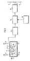
- the treatment apparatus is characterized in that the means for controlling the opening or closing of the valve consist of a chamber in which is placed a reservoir in the form of a flexible balloon, this reservoir having an opening opening to the ambient air through a partition in the chamber, a screen secured to a movable wall of said tank, an optoelectronic device comprising a transmitter and a receiver of a light beam, a circuit control electronics connected, on the one hand, to the receiver and, on the other hand, to the valve, as well as a second conduit connecting the chamber to the patient's mouth or nostrils, the movable wall of said reservoir being subjected to one side at ambient air pressure and the other at air pressure in the room coming from / where going to the patient via the second duct, the pressure difference between and other of the movable wall of the tank e generating a displacement of the screen in the direction of the gas of lower pressure, so that the screen comes to cut at least partially or ceases to cut completely the light beam between transmitter and receiver, said receiver generating signals for
- the operation consists in moving the movable wall down: the light beam which was not interrupted when the movable wall was at rest is interrupted when the movable wall is moved down.
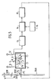
- the apparatus for the treatment of a patient's respiratory deficiencies is characterized in that the means for controlling the opening or closing of the valve consist of a chamber in which a reservoir is placed in the form of a flexible bladder, a screen secured to a movable wall of said reservoir, an optoelectronic device comprising a transmitter and a receiver of a light beam, an electronic control circuit connected , of a on the one hand, to the receiver and, on the other hand, to the valve, as well as a second conduit connecting the interior of the tank to the first conduit downstream of the valve, the interior of the chamber being vented to the by means of a hole drilled in one of the walls of this chamber, so that the movable wall of said tank is subjected on the side of the chamber to the pressure of the ambient air and on the other to the pressure of the ducted air , the pressure difference on either side of the movable wall of the generating tank. a displacement of the screen in the direction of the gas of lower pressure, so that the screen comes to
- the operation consists in moving the wall upwards: the light beam initially interrupted by. the screen when the wall is horizontal is no longer when the wall is moved up.
- the device can trigger the opening of the oxygen injection valve (or of another gas or fluid) either at the end of the patient's expiration phase, i.e. at the start of the patient's inspiration phase.
- the beam is not interrupted when the movable wall is moved upwards, but is interrupted (partially or completely) only when the movable wall is moved towards the bottom.
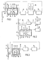
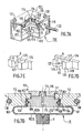
- the vacuum sensor which is shown in fig. 1 and which is designated as a whole by the reference 1, is intended to control a solenoid valve 2 connected to a line 3 of oxygen supply which is connected to an oxygen therapy scope of which only the extreme part 4 is shown in the drawing .
- the low depression detector 1 comprises a sealed chamber 5 inside which are housed, on the one hand, a very sensitive balloon 6 and, on the other hand, an optoelectronic sensor 7.
- the balloon 6 used in the following detector the invention may have, for example, a diameter of 28.4 mm and a thickness of 0.2 mm and it can be made of silicone, of the type known under the name VERSILIC 3706H manufactured by SOCIETE VERNEPET.
- the balloon 6 is supported on a wall of the chamber 5 and its internal volume communicates with the outside by the intermediary of a hole 8 drilled in this wall, so that the balloon 6 is subjected, inside, to atmospheric pressure.
- the slight depression appearing in the oxygen therapy scope 4 is transmitted through the conduit 19 inside the bladder 6 so that it is crushed by retracting the screen 9.
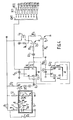
- the light beam emitted by the transmitter 7a is then picked up by the receiver 7b, which results in the emission of a pulse of the engagement of the opening of the valve 2, for a duration chosen at will, by means of the circuit 16, as in the case of the example shown in FIG. 1.
Landscapes
- Health & Medical Sciences (AREA)
- Pulmonology (AREA)
- Life Sciences & Earth Sciences (AREA)
- Engineering & Computer Science (AREA)
- Public Health (AREA)
- Veterinary Medicine (AREA)
- Anesthesiology (AREA)
- Biomedical Technology (AREA)
- Heart & Thoracic Surgery (AREA)
- Hematology (AREA)
- Animal Behavior & Ethology (AREA)
- General Health & Medical Sciences (AREA)
- Emergency Medicine (AREA)
- Otolaryngology (AREA)
- Biophysics (AREA)
- Bioinformatics & Cheminformatics (AREA)
- Physics & Mathematics (AREA)
- General Physics & Mathematics (AREA)
- Respiratory Apparatuses And Protective Means (AREA)
- Pharmaceuticals Containing Other Organic And Inorganic Compounds (AREA)
- Measurement Of The Respiration, Hearing Ability, Form, And Blood Characteristics Of Living Organisms (AREA)
- External Artificial Organs (AREA)
- Control Of Fluid Pressure (AREA)
- Investigating Or Analysing Materials By Optical Means (AREA)
- Separation Of Particles Using Liquids (AREA)
Claims (12)
Priority Applications (1)
| Application Number | Priority Date | Filing Date | Title |
|---|---|---|---|
| AT85402160T ATE49350T1 (de) | 1984-11-13 | 1985-11-08 | Beatmungsgeraet. |
Applications Claiming Priority (2)
| Application Number | Priority Date | Filing Date | Title |
|---|---|---|---|
| FR8417236 | 1984-11-13 | ||
| FR8417236A FR2573204B1 (fr) | 1984-11-13 | 1984-11-13 | Detecteur de depressions inferieures au mm d'eau |
Publications (2)
| Publication Number | Publication Date |
|---|---|
| EP0183593A1 EP0183593A1 (de) | 1986-06-04 |
| EP0183593B1 true EP0183593B1 (de) | 1990-01-10 |
Family
ID=9309511
Family Applications (1)
| Application Number | Title | Priority Date | Filing Date |
|---|---|---|---|
| EP85402160A Expired - Lifetime EP0183593B1 (de) | 1984-11-13 | 1985-11-08 | Beatmungsgerät |
Country Status (9)
| Country | Link |
|---|---|
| US (1) | US4848332A (de) |
| EP (1) | EP0183593B1 (de) |
| JP (1) | JPS61154572A (de) |
| AT (1) | ATE49350T1 (de) |
| DE (1) | DE3575262D1 (de) |
| ES (1) | ES8701381A1 (de) |
| FR (1) | FR2573204B1 (de) |
| GR (1) | GR852749B (de) |
| PT (1) | PT81469B (de) |
Families Citing this family (17)
| Publication number | Priority date | Publication date | Assignee | Title |
|---|---|---|---|---|
| FR2611505B1 (fr) * | 1987-03-05 | 1997-01-10 | Air Liquide | Procede et dispositif d'alimentation en oxygene respiratoire |
| FR2631834B1 (fr) * | 1988-05-24 | 1990-09-07 | Air Liquide | Procede et dispositif d'alimentation en gaz respiratoire |
| GB8815179D0 (en) * | 1988-06-25 | 1988-08-03 | Racal Safety Ltd | Differential pressure sensor |
| GB9125467D0 (en) * | 1991-11-29 | 1992-01-29 | Mockridge Jeffrey N A | Neo-natal ventilation apparatus |
| CA2096302A1 (en) * | 1992-05-15 | 1993-11-16 | David Kilis | Air flow controller and recording system |
| FR2695831B1 (fr) * | 1992-09-24 | 1994-11-10 | Air Liquide | Installation et procédé de fourniture d'un mélange gazeux aux voies respiratoires d'un utilisateur. |
| IT1272156B (it) * | 1993-03-26 | 1997-06-11 | Cesare Gallone | Pressostato ad alta sensibilita' e precisione |
| GB9320978D0 (en) * | 1993-10-12 | 1993-12-01 | Higenbottam Timohy W | Nitric oxide treatment |
| DE9406407U1 (de) * | 1994-04-18 | 1995-08-17 | Schneider, Peter, 56759 Laubach | Sauerstofftherapiegerät |
| FR2727022B1 (fr) * | 1994-11-21 | 1997-05-23 | Taema | Dispositif de commande d'assistance respiratoire |
| AUPN394895A0 (en) * | 1995-07-03 | 1995-07-27 | Rescare Limited | Auto-calibration of pressure transducer offset |
| US5881725A (en) * | 1997-08-19 | 1999-03-16 | Victor Equipment Company | Pneumatic oxygen conserver |
| JP4080591B2 (ja) * | 1998-04-24 | 2008-04-23 | 株式会社群馬コイケ | 呼吸同調型酸素供給装置 |
| US6364161B1 (en) | 2000-09-27 | 2002-04-02 | Victor Equipment Company | Oxygen conserver |
| US6910482B2 (en) * | 2001-10-19 | 2005-06-28 | Chart Inc. | Self-calibrating supplemental oxygen delivery system |
| CN102313622A (zh) * | 2011-05-19 | 2012-01-11 | 常州大学 | 电容检测电路及电容式压力变送器 |
| FR2985432B1 (fr) * | 2012-01-11 | 2015-07-24 | Diffusion Tech Francaise Sarl | Perfectionnement a un dispositif pour appliquer un stimulus de pression pneumatique dans les fosses nasales et dans la trompe auditive au moment de la deglutition |
Family Cites Families (11)
| Publication number | Priority date | Publication date | Assignee | Title |
|---|---|---|---|---|
| US2223705A (en) * | 1937-04-26 | 1940-12-03 | Roudnicky Rudolf | Pressure gauge with barometric correction |
| US3137158A (en) * | 1962-01-12 | 1964-06-16 | Woodson C Deeds | Air density meter |
| US3502892A (en) * | 1966-10-24 | 1970-03-24 | Radon Ind Electronics Co Ltd | Pressure-sensitive optical switch |
| US3831596A (en) * | 1971-11-10 | 1974-08-27 | Synthelabo | Control device for a respiratory apparatus |
| JPS5239167U (de) * | 1975-09-10 | 1977-03-19 | ||
| US4054133A (en) * | 1976-03-29 | 1977-10-18 | The Bendix Corporation | Control for a demand cannula |
| JPS5321972A (en) * | 1976-08-12 | 1978-02-28 | Matsushita Electric Ind Co Ltd | Apparatus for converting pressure into electric signal |
| SE407738B (sv) * | 1977-09-15 | 1979-04-23 | Electrolux Ab | Indikatoranordning for dammsugare |
| US4289963A (en) * | 1979-09-17 | 1981-09-15 | Robertshaw Controls Company | Control device and method of making the same |
| GB2089497B (en) * | 1980-12-12 | 1985-01-30 | Imed Corp | Control of pressure of fluid delivered by a pump |
| US4599902A (en) * | 1984-10-01 | 1986-07-15 | Span Instruments, Inc. | Condition responsive apparatus |
-
1984
- 1984-11-13 FR FR8417236A patent/FR2573204B1/fr not_active Expired
-
1985
- 1985-11-08 EP EP85402160A patent/EP0183593B1/de not_active Expired - Lifetime
- 1985-11-08 DE DE8585402160T patent/DE3575262D1/de not_active Expired - Lifetime
- 1985-11-08 AT AT85402160T patent/ATE49350T1/de not_active IP Right Cessation
- 1985-11-12 ES ES548787A patent/ES8701381A1/es not_active Expired
- 1985-11-12 PT PT81469A patent/PT81469B/pt not_active IP Right Cessation
- 1985-11-13 JP JP60252980A patent/JPS61154572A/ja active Pending
- 1985-11-13 GR GR852749A patent/GR852749B/el unknown
-
1988
- 1988-02-25 US US07/163,145 patent/US4848332A/en not_active Expired - Fee Related
Also Published As
| Publication number | Publication date |
|---|---|
| FR2573204B1 (fr) | 1987-01-30 |
| GR852749B (de) | 1986-03-12 |
| US4848332A (en) | 1989-07-18 |
| EP0183593A1 (de) | 1986-06-04 |
| JPS61154572A (ja) | 1986-07-14 |
| ES548787A0 (es) | 1986-11-16 |
| ES8701381A1 (es) | 1986-11-16 |
| ATE49350T1 (de) | 1990-01-15 |
| PT81469B (pt) | 1987-09-18 |
| FR2573204A1 (fr) | 1986-05-16 |
| DE3575262D1 (de) | 1990-02-15 |
| PT81469A (en) | 1985-12-01 |
Similar Documents
| Publication | Publication Date | Title |
|---|---|---|
| EP0183593A1 (de) | Beatmungsgerät | |
| EP0091843B1 (de) | Anschlussstück für Atmungsgerät, zur Verbindung der Maske mit einer Gasflasche | |
| IL283145B1 (en) | Spray delivery device | |
| FR2459052A1 (fr) | Inhalateur avec logement muni d'un moyen de fixation pour recevoir alternativement au choix deux reservoirs a liquide servant a des fins differentes | |
| FR2479003A1 (fr) | Dispositif d'administration d'un gaz anesthesique a un patient | |
| WO2016193643A1 (fr) | Soupape pour appareil de cuisson sous pression et appareil de cuisson sous pression equipe d'une telle soupape | |
| FR2763507A1 (fr) | Inhalateur | |
| FR2704183A1 (fr) | Instrument d'écriture ou de dessin. | |
| FR2639236A1 (fr) | Appareil generateur d'aerosols perfectionne avec effets soniques | |
| FR2640875A1 (de) | ||
| EP0861188B1 (de) | Autonomes tauchgerät | |
| FR2573658A1 (fr) | Dispositif de pression expiratoire positive | |
| CA2017618A1 (fr) | Dispositif de detection a micro-onde d'air notamment pour le controle et la surveillance de la respiration | |
| EP0236208B1 (de) | Unterwasser-Atmungsgerät für zusammengepresste Luft | |
| FR2459646A1 (fr) | Appareil de commande de debit pour dispositif de controle de la pression sanguine, ou analogue | |
| FR2488296A1 (fr) | Fer a repasser a vapeur | |
| FR2784587A1 (fr) | Appareil d'assistance respiratoire comportant des moyens perfectionnes de commande d'une valve d'expiration | |
| EP1374826A1 (de) | Vorrichtung um in Verbindung zu treten mit der Umgebungsluft, bestimmt zum platzieren auf einen Behälter wie eine Saugflasche | |
| FR3115701A1 (fr) | Dispositif lumineux de ventilation respiratoire | |
| EP0224309B1 (de) | Mit einer automatischen Saugkontrollvorrichtung ausgerüsteter Staubsauger | |
| FR2769229A1 (fr) | Dispositif mouche nez pour bebe | |
| BE898456A (fr) | Dispositif pour la capture et l'extermination des insectes. | |
| EP1604166A1 (de) | Vorrichtung zur auswerfung leichter stoffe wie konfetti oder dergleichen und/oder emulsionen wie schaum, schnee oder dergleichen | |
| WO1991002677A1 (fr) | Appareillage individuel de plongee | |
| FR2690623A1 (fr) | Dispositif de contrôle de débit pour systèmes de perfusion. |
Legal Events
| Date | Code | Title | Description |
|---|---|---|---|
| PUAI | Public reference made under article 153(3) epc to a published international application that has entered the european phase |
Free format text: ORIGINAL CODE: 0009012 |
|
| 17P | Request for examination filed |
Effective date: 19851115 |
|
| AK | Designated contracting states |
Kind code of ref document: A1 Designated state(s): AT BE CH DE FR GB IT LI LU NL SE |
|
| 17Q | First examination report despatched |
Effective date: 19880406 |
|
| GRAA | (expected) grant |
Free format text: ORIGINAL CODE: 0009210 |
|
| AK | Designated contracting states |
Kind code of ref document: B1 Designated state(s): AT BE CH DE FR GB IT LI LU NL SE |
|
| REF | Corresponds to: |
Ref document number: 49350 Country of ref document: AT Date of ref document: 19900115 Kind code of ref document: T |
|
| ITF | It: translation for a ep patent filed | ||
| REF | Corresponds to: |
Ref document number: 3575262 Country of ref document: DE Date of ref document: 19900215 |
|
| GBT | Gb: translation of ep patent filed (gb section 77(6)(a)/1977) | ||
| PLBE | No opposition filed within time limit |
Free format text: ORIGINAL CODE: 0009261 |
|
| STAA | Information on the status of an ep patent application or granted ep patent |
Free format text: STATUS: NO OPPOSITION FILED WITHIN TIME LIMIT |
|
| 26N | No opposition filed | ||
| ITTA | It: last paid annual fee | ||
| EPTA | Lu: last paid annual fee | ||
| EAL | Se: european patent in force in sweden |
Ref document number: 85402160.7 |
|
| PGFP | Annual fee paid to national office [announced via postgrant information from national office to epo] |
Ref country code: LU Payment date: 19961001 Year of fee payment: 12 |
|
| PGFP | Annual fee paid to national office [announced via postgrant information from national office to epo] |
Ref country code: FR Payment date: 19961010 Year of fee payment: 12 |
|
| PGFP | Annual fee paid to national office [announced via postgrant information from national office to epo] |
Ref country code: AT Payment date: 19961015 Year of fee payment: 12 |
|
| PGFP | Annual fee paid to national office [announced via postgrant information from national office to epo] |
Ref country code: SE Payment date: 19961018 Year of fee payment: 12 |
|
| PGFP | Annual fee paid to national office [announced via postgrant information from national office to epo] |
Ref country code: BE Payment date: 19961021 Year of fee payment: 12 |
|
| PGFP | Annual fee paid to national office [announced via postgrant information from national office to epo] |
Ref country code: GB Payment date: 19961022 Year of fee payment: 12 |
|
| PGFP | Annual fee paid to national office [announced via postgrant information from national office to epo] |
Ref country code: NL Payment date: 19961024 Year of fee payment: 12 Ref country code: DE Payment date: 19961024 Year of fee payment: 12 |
|
| PGFP | Annual fee paid to national office [announced via postgrant information from national office to epo] |
Ref country code: CH Payment date: 19961028 Year of fee payment: 12 |
|
| PG25 | Lapsed in a contracting state [announced via postgrant information from national office to epo] |
Ref country code: LU Free format text: LAPSE BECAUSE OF NON-PAYMENT OF DUE FEES Effective date: 19971108 Ref country code: GB Free format text: LAPSE BECAUSE OF NON-PAYMENT OF DUE FEES Effective date: 19971108 Ref country code: AT Free format text: LAPSE BECAUSE OF NON-PAYMENT OF DUE FEES Effective date: 19971108 |
|
| PG25 | Lapsed in a contracting state [announced via postgrant information from national office to epo] |
Ref country code: SE Free format text: LAPSE BECAUSE OF NON-PAYMENT OF DUE FEES Effective date: 19971109 |
|
| PG25 | Lapsed in a contracting state [announced via postgrant information from national office to epo] |
Ref country code: LI Free format text: LAPSE BECAUSE OF NON-PAYMENT OF DUE FEES Effective date: 19971130 Ref country code: FR Free format text: THE PATENT HAS BEEN ANNULLED BY A DECISION OF A NATIONAL AUTHORITY Effective date: 19971130 Ref country code: CH Free format text: LAPSE BECAUSE OF NON-PAYMENT OF DUE FEES Effective date: 19971130 Ref country code: BE Free format text: LAPSE BECAUSE OF NON-PAYMENT OF DUE FEES Effective date: 19971130 |
|
| BERE | Be: lapsed |
Owner name: S.A. L' AIR LIQUIDE POUR L'ETUDE ET L'EXPLOITATION Effective date: 19971130 |
|
| PG25 | Lapsed in a contracting state [announced via postgrant information from national office to epo] |
Ref country code: NL Free format text: LAPSE BECAUSE OF NON-PAYMENT OF DUE FEES Effective date: 19980601 |
|
| GBPC | Gb: european patent ceased through non-payment of renewal fee |
Effective date: 19971108 |
|
| REG | Reference to a national code |
Ref country code: CH Ref legal event code: PL |
|
| PG25 | Lapsed in a contracting state [announced via postgrant information from national office to epo] |
Ref country code: DE Free format text: LAPSE BECAUSE OF NON-PAYMENT OF DUE FEES Effective date: 19980801 |
|
| EUG | Se: european patent has lapsed |
Ref document number: 85402160.7 |
|
| NLV4 | Nl: lapsed or anulled due to non-payment of the annual fee |
Effective date: 19980601 |
|
| REG | Reference to a national code |
Ref country code: FR Ref legal event code: ST |