EP0183597A1 - Schutzschaltung gegen den Ausfall der elektrischen Versorgung - Google Patents
Schutzschaltung gegen den Ausfall der elektrischen Versorgung Download PDFInfo
- Publication number
- EP0183597A1 EP0183597A1 EP85402167A EP85402167A EP0183597A1 EP 0183597 A1 EP0183597 A1 EP 0183597A1 EP 85402167 A EP85402167 A EP 85402167A EP 85402167 A EP85402167 A EP 85402167A EP 0183597 A1 EP0183597 A1 EP 0183597A1
- Authority
- EP
- European Patent Office
- Prior art keywords
- voltage
- circuit
- capacitor
- output
- input
- Prior art date
- Legal status (The legal status is an assumption and is not a legal conclusion. Google has not performed a legal analysis and makes no representation as to the accuracy of the status listed.)
- Withdrawn
Links
Images

Classifications
-
- H—ELECTRICITY
- H02—GENERATION; CONVERSION OR DISTRIBUTION OF ELECTRIC POWER
- H02J—ELECTRIC POWER NETWORKS; CIRCUIT ARRANGEMENTS OR SYSTEMS FOR SUPPLYING OR DISTRIBUTING ELECTRIC POWER; SYSTEMS FOR STORING ELECTRIC ENERGY
- H02J9/00—Circuit arrangements for emergency or stand-by power supply, e.g. for emergency lighting
- H02J9/04—Circuit arrangements for emergency or stand-by power supply, e.g. for emergency lighting in which the distribution system is disconnected from the normal source and connected to a standby source
- H02J9/06—Circuit arrangements for emergency or stand-by power supply, e.g. for emergency lighting in which the distribution system is disconnected from the normal source and connected to a standby source with automatic change-over, e.g. UPS systems
- H02J9/061—Circuit arrangements for emergency or stand-by power supply, e.g. for emergency lighting in which the distribution system is disconnected from the normal source and connected to a standby source with automatic change-over, e.g. UPS systems for DC powered loads
Definitions
- the invention applies to supply networks which present significant overvoltages and drops in voltage.
- the voltage is affected by micro-cuts which drop the network voltage to 0V, by momentary voltage drops to around 12V, while momentary overvoltages can go up to 80V, and this during sudden load variations.
- Micro-cuts can be compensated using a protection circuit as long as they do not exceed a too long duration (the maximum range provided can be 50 milliseconds).
- an energy reservoir generally a capacitor
- the capacitor must be able to withstand the maximum envisaged overvoltage, for example 80V. Its load at the network voltage, 20 to 30V, offers a limited usable energy reserve.
- the object of the invention is to increase the quantity of energy available, so as to withstand cuts of longer duration, for example 250 milliseconds, as well as sharp drops in voltage.
- the object of the invention is a circuit for protection against power outages, using a capacitor to store continuous electrical energy and supply it during outages, said circuit being interposed on a continuous power network delivering before regulation.
- a DC input voltage characterized in that it comprises means for charging the capacitor at a predetermined voltage and greater than the input voltage, a diode switch receiving said DC input voltage, switching means for connecting the capacitor in place of the network in the event of a cut, these means comprising a cut-off detector circuit supplied by said DC input voltage and the output of which controls a switch which connects the capacitor to the output of the charging means in normal operation, and in the event of a mains failure at the output of said diode, this latter connection being effected through a step-down circuit.
- the protection circuit according to the invention comprises a storage element and the circuits and members necessary for charging and discharging it. I! is connected to a power supply network with a voltage regulator.
- the element for storing electrical energy is the capacitor 2, which supplies power during the power cuts to the network and to its regulation circuit 10, delivering a voltage for using the network V S .
- the circuit receives at its input the DC voltage VE of the network, direct or alternately rectified.
- a charging circuit 4 receives the input voltage V E. It includes regulating elements and transformer elements for delivering a predetermined charging voltage V 1 much higher than the input voltage VE of the device. If the latter varies from 0 to 30 Volts, V 1 will advantageously be chosen at 80 Volts.
- a cut-off detector circuit 14 is used.
- this cut-off detector controls a switch 12.
- the latter in normal operation, connects the output of the regulator-charger circuit 4 to a first frame of the capacitor 2 so that the latter is charged at the voltage V 1 , the second armature being connected to a reference potential.
- the input voltage of the device VE is applied to the input of the regulation circuit 10 via a stop diode 16.
- the cut-off detector controls the change of state of the switch 12.
- the latter then connects the capacitor 12 to the network through a voltage step-down circuit 6 consisting for example of a resistor. This voltage step-down circuit makes it possible to supply the regulator-charger circuit 10 at its input voltage V 2 during the micro-cut-off.
- C being the capacity of capacitor 2, the energy delivered by it is proportional to C (V 2 1 - V 2 2 ).
- the capacitor is always charged at the charging voltage V 1 .
- the latter and the input voltage V 2 of the regulating circuit are chosen so that the energy stored by the capacitor 2 is sufficient to overcome a micro-cutout of fixed duration and allow the regulating circuit 10 to deliver the voltage V S network usage.
- This first assembly is used when the output voltage V S is less than the input voltage V E , the regulator 10 then being a voltage step-down regulator.
- FIG. 2 shows a second arrangement for a voltage step-up regulator, that is to say that the output voltage V is greater than the input voltage V 1 . It is assumed in this case that the difference between these two input and output voltages is sufficient for the capacitor 2 to be charged at the output voltage V S. The charging circuit is thus eliminated.
- the capacitor 2, in normal mode, is connected by the switch 12 to the output of the voltage-boosting regulating circuit 11.
- a cut-off detector circuit 14 is also used in this device which controls the change of state of the switch 12 when a micro-cut appears at the input of the circuit.
- the capacitor is then connected to a voltage step-down 6 which feeds the input of the regulation circuit 11.
- the capacitor discharges at the input voltage V 2 of input of the regulation circuit which is lower than the output voltage V S.
- a stop diode 16 is always used between the regulation circuit 11 and the input of the device.
- the output voltages V S and input V 2 of the regulation circuit 11 are chosen so that the energy stored in the capacitor makes it possible to compensate for micro-cuts of predetermined duration. In this case also, despite possible variations in the input voltage VE, the capacitor will always be charged at the output voltage V S.
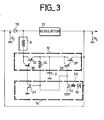
- FIG. 3 is shown an embodiment of the circuit mounted with a voltage step-up regulator in accordance with the diagram in FIG. 2.
- the input of the detector 14 receives the input voltage V E at the cathode of a Zenner diode 18.
- a resistor 20 is connected to the anode of this diode by its first end and to the base of a first NPN transistor 22 whose emitter is connected to a reference potential.
- the collector of this first transistor is used to control one of the two binary states of the switch 12. It is also connected to the base of a second NPN transistor 24, the emitter of which is also connected to the same reference potential.
- the collector of this second NPN transistor is used to control the second state of switch 12.
- the switch 12 can be produced in the following manner with two assemblies of two transistors mounted in cascade, and with the collector in common. More specifically, a first PNP transistor 26 receives by its emitter the output voltage V S , its base being connected to the emitter of a second PNP transistor 28 whose base receives the signal from the collector of transistor 22. The collectors of these two transistors-26, 28 are connected to the load armature of the capacitor 2. Similarly, a third PNP transistor 32 is connected by its base to the emitter of a fourth PNP transistor 30, the base of which receives the signal from the collector of transistor 24. The collectors of the two transistors 30 and 32 are connected to the input of the step-down circuit 6. The output of the latter is applied to the input of the regulator circuit 11, the emitter of the transistor 32 being connected to the load armature of the capacitor 2. A resistor 34 is connected on the one hand to the base of transistor 24, and on the other hand to the emitter of transistor 32.
- This circuit is particularly suitable for overcoming the micro-cuts of the order of 50 milliseconds which may arise on the supply network (s), for example those of aircraft.
Landscapes
- Business, Economics & Management (AREA)
- Emergency Management (AREA)
- Engineering & Computer Science (AREA)
- Power Engineering (AREA)
- Direct Current Feeding And Distribution (AREA)
- Stand-By Power Supply Arrangements (AREA)
Applications Claiming Priority (2)
| Application Number | Priority Date | Filing Date | Title |
|---|---|---|---|
| FR8417294 | 1984-11-13 | ||
| FR8417294A FR2573257B1 (fr) | 1984-11-13 | 1984-11-13 | Circuit de protection contre les coupures d'alimentation electrique |
Publications (1)
| Publication Number | Publication Date |
|---|---|
| EP0183597A1 true EP0183597A1 (de) | 1986-06-04 |
Family
ID=9309542
Family Applications (1)
| Application Number | Title | Priority Date | Filing Date |
|---|---|---|---|
| EP85402167A Withdrawn EP0183597A1 (de) | 1984-11-13 | 1985-11-08 | Schutzschaltung gegen den Ausfall der elektrischen Versorgung |
Country Status (2)
| Country | Link |
|---|---|
| EP (1) | EP0183597A1 (de) |
| FR (1) | FR2573257B1 (de) |
Cited By (14)
| Publication number | Priority date | Publication date | Assignee | Title |
|---|---|---|---|---|
| EP0315830A1 (de) * | 1987-11-10 | 1989-05-17 | Siemens Aktiengesellschaft | Netzteil für ein elektronisches Gerät mit Kondensatorpufferung |
| WO1991000637A1 (de) * | 1989-06-29 | 1991-01-10 | Robert Bosch Gmbh | Spannungsversorgungseinrichtung für ein elektronisches gerät |
| GB2262003A (en) * | 1991-11-23 | 1993-06-02 | Motorola Gmbh | Arrangement for protection against drop in supply voltage |
| EP0570704A3 (en) * | 1992-04-23 | 1994-07-20 | Siemens Ag Oesterreich | Flyback converter |
| EP0647366A4 (de) * | 1992-06-22 | 1995-06-07 | Nat Environmental Prod | Kapazitive stromversorgung für klappen- und antriebsmotoren. |
| WO1999044269A1 (en) * | 1998-02-24 | 1999-09-02 | Lucas Industries Plc | Power supplies for ecus |
| WO1999048185A1 (en) * | 1998-03-17 | 1999-09-23 | Telefonaktiebolaget Lm Ericsson (Publ) | Electrical power management system |
| EP0911942A3 (de) * | 1997-10-22 | 1999-12-01 | TEMIC TELEFUNKEN microelectronic GmbH | Verfahren und Schaltungsanordnung zur kurzzeitigen Aufrechterhaltung einer Ausgangsspannung bei Ausfällen einer Eingangsspannung mittels eines Autarkiekondensators |
| WO2001093404A1 (de) * | 2000-05-31 | 2001-12-06 | Siemens Ag Österreich | Pufferschaltung |
| US6597073B1 (en) * | 1998-02-18 | 2003-07-22 | Compaq Information Technologies Group, L.P. | Circuit and method for providing power supply redundancy |
| EP1478083A3 (de) * | 2003-05-15 | 2005-11-30 | STMicroelectronics, Inc. | Konstantspannungsentladungsgerät |
| DE19542085B4 (de) * | 1994-12-30 | 2007-07-05 | Robert Bosch Gmbh | Sicherheitseinrichtung für Fahrzeuginsassen |
| CN1328837C (zh) * | 2004-03-17 | 2007-07-25 | 海信集团有限公司 | 税控收款机的电源监控方法 |
| US20110199017A1 (en) * | 2010-02-15 | 2011-08-18 | Osram Gesellschaft Mit Beschraenkter Haftung | Circuit and method for driving a luminous means |
Families Citing this family (1)
| Publication number | Priority date | Publication date | Assignee | Title |
|---|---|---|---|---|
| US8324863B2 (en) * | 2010-04-19 | 2012-12-04 | Tesla Motors, Inc. | Trickle charger for high-energy storage systems |
Citations (3)
| Publication number | Priority date | Publication date | Assignee | Title |
|---|---|---|---|---|
| US3631257A (en) * | 1970-06-01 | 1971-12-28 | Union Carbide Corp | Automatic power switching unit |
| US4220872A (en) * | 1978-12-26 | 1980-09-02 | Gte Sylvania Incorporated | DC power supply circuit |
| DE3045445A1 (de) * | 1980-12-02 | 1982-07-01 | Siemens AG, 1000 Berlin und 8000 München | Schaltungsanordnung zur strom- und spannungsversorgung bei netzausfall |
-
1984
- 1984-11-13 FR FR8417294A patent/FR2573257B1/fr not_active Expired
-
1985
- 1985-11-08 EP EP85402167A patent/EP0183597A1/de not_active Withdrawn
Patent Citations (3)
| Publication number | Priority date | Publication date | Assignee | Title |
|---|---|---|---|---|
| US3631257A (en) * | 1970-06-01 | 1971-12-28 | Union Carbide Corp | Automatic power switching unit |
| US4220872A (en) * | 1978-12-26 | 1980-09-02 | Gte Sylvania Incorporated | DC power supply circuit |
| DE3045445A1 (de) * | 1980-12-02 | 1982-07-01 | Siemens AG, 1000 Berlin und 8000 München | Schaltungsanordnung zur strom- und spannungsversorgung bei netzausfall |
Non-Patent Citations (2)
| Title |
|---|
| ELECTRONIC ENGINEERING, vol. 56, no. 685, janvier 1984, pages 70-76, Londres, GB; "Product Focus, Power supplies" * |
| IBM TECHNICAL DISCLOSURE BULLETIN, vol. 14, no. 1, juin 1971, pages 68-69, New York, US; R.A. TENLEY: "Power line disturbance support circuit" * |
Cited By (23)
| Publication number | Priority date | Publication date | Assignee | Title |
|---|---|---|---|---|
| EP0315830A1 (de) * | 1987-11-10 | 1989-05-17 | Siemens Aktiengesellschaft | Netzteil für ein elektronisches Gerät mit Kondensatorpufferung |
| WO1991000637A1 (de) * | 1989-06-29 | 1991-01-10 | Robert Bosch Gmbh | Spannungsversorgungseinrichtung für ein elektronisches gerät |
| GB2262003A (en) * | 1991-11-23 | 1993-06-02 | Motorola Gmbh | Arrangement for protection against drop in supply voltage |
| EP0570704A3 (en) * | 1992-04-23 | 1994-07-20 | Siemens Ag Oesterreich | Flyback converter |
| EP0647366A4 (de) * | 1992-06-22 | 1995-06-07 | Nat Environmental Prod | Kapazitive stromversorgung für klappen- und antriebsmotoren. |
| DE19542085B4 (de) * | 1994-12-30 | 2007-07-05 | Robert Bosch Gmbh | Sicherheitseinrichtung für Fahrzeuginsassen |
| EP0911942A3 (de) * | 1997-10-22 | 1999-12-01 | TEMIC TELEFUNKEN microelectronic GmbH | Verfahren und Schaltungsanordnung zur kurzzeitigen Aufrechterhaltung einer Ausgangsspannung bei Ausfällen einer Eingangsspannung mittels eines Autarkiekondensators |
| US6097109A (en) * | 1997-10-22 | 2000-08-01 | Temic Telefunken Microelectronic Gmbh | Process and circuit layout for using an independent capacitor for the momentary retention of an output voltage when an input voltage is lost |
| US6597073B1 (en) * | 1998-02-18 | 2003-07-22 | Compaq Information Technologies Group, L.P. | Circuit and method for providing power supply redundancy |
| WO1999044269A1 (en) * | 1998-02-24 | 1999-09-02 | Lucas Industries Plc | Power supplies for ecus |
| US6614134B1 (en) | 1998-02-24 | 2003-09-02 | Lucas Industries Plc | Power supplies for ECUs |
| US6153949A (en) * | 1998-03-17 | 2000-11-28 | Telefonaktiebolaget Lm Ericsson | Electrical power management system providing momentarily high power to a load |
| WO1999048185A1 (en) * | 1998-03-17 | 1999-09-23 | Telefonaktiebolaget Lm Ericsson (Publ) | Electrical power management system |
| WO2001093404A1 (de) * | 2000-05-31 | 2001-12-06 | Siemens Ag Österreich | Pufferschaltung |
| US7355303B2 (en) | 2003-05-15 | 2008-04-08 | Stmicroelectronics, Inc. | Constant voltage discharge device |
| EP1478083A3 (de) * | 2003-05-15 | 2005-11-30 | STMicroelectronics, Inc. | Konstantspannungsentladungsgerät |
| US7098557B2 (en) | 2003-05-15 | 2006-08-29 | Stmicroelectronics, Inc. | Constant voltage discharge device |
| CN1328837C (zh) * | 2004-03-17 | 2007-07-25 | 海信集团有限公司 | 税控收款机的电源监控方法 |
| US20110199017A1 (en) * | 2010-02-15 | 2011-08-18 | Osram Gesellschaft Mit Beschraenkter Haftung | Circuit and method for driving a luminous means |
| DE102010001919A1 (de) * | 2010-02-15 | 2011-08-18 | Osram Gesellschaft mit beschränkter Haftung, 81543 | Schaltung und Verfahren zur Ansteuerung eines Leuchtmittels |
| CN102164435A (zh) * | 2010-02-15 | 2011-08-24 | 欧司朗有限责任公司 | 用于触发发光机构的电路和方法 |
| DE102010001919B4 (de) * | 2010-02-15 | 2012-03-01 | Osram Ag | Schaltung und Verfahren zur Ansteuerung eines Leuchtmittels |
| US8816598B2 (en) * | 2010-02-15 | 2014-08-26 | Osram Gesellschaft Mit Beschraenkter Haftung | Circuit and method for driving a luminous means |
Also Published As
| Publication number | Publication date |
|---|---|
| FR2573257B1 (fr) | 1987-01-02 |
| FR2573257A1 (fr) | 1986-05-16 |
Similar Documents
| Publication | Publication Date | Title |
|---|---|---|
| EP0110775B1 (de) | Regulierungseinrichtung mit kleiner Verlustspannung | |
| EP0017892B1 (de) | Automatische Umschaltvorrichtung zum parallelen Aufladen und serienmässigen Entladen zweier Batterien | |
| EP2351188B1 (de) | Ununterbrechbare gleichstrom-stromversorgungseinrichtung für ein datenverarbeitungssystem mit mindestens einem prozessor | |
| EP1202426B1 (de) | Universelles Batterieladegerät und Verfahren | |
| EP0847124B1 (de) | Notstromversorgungseinrichtung zur provisorischen Stromversorgung im Falle eines Versagens der Hauptstromversorgung | |
| FR2573257A1 (fr) | Circuit de protection contre les coupures d'alimentation electrique | |
| EP1009003B1 (de) | Einrichtung zur Steuerung eines Elektromagneten, mit von Haltestrom gespeisten Stromversorgung | |
| FR2910141A1 (fr) | Systeme de generation d'energie electrique avec maximisation de la puissance | |
| EP2363939B1 (de) | Unterbrechungsfreie Wechselstromversorgung einer Installation und Verfahren dazu | |
| EP1356569B1 (de) | Elekrische speisungsvorrichtung mit hohem sicherheitsgrad | |
| EP0544566B1 (de) | Stromquellenkontrollmodul für Batteriekontrolleinheit und Batterie mit diesem Modul | |
| EP1209709B1 (de) | Elektrische Schaltungsanordnung zur Meldung von Zustandsinformationen, insbesondere für Eisenbahnmaterial, und System mit einer solchen Einrichtung | |
| EP0654885B1 (de) | Stromversorgungsvorrichtung für die Steuerschaltung eines Leistungsschalters | |
| CA2281637C (fr) | Dispositif d'alimentation faible cout d'une pluralite de modules electroniques installes dans une baie | |
| EP1139361B1 (de) | Elektrische Schaltungsanordnung zur Meldung von Zustandsinformationen, insbesondere für Eisenbahnmaterial, und System mit einer solchen Einrichtung | |
| EP0077531A1 (de) | Ladeeinrichtung für eine Batteriegruppe, insbesondere für Pufferbatterien die durch eine leistungsbegrenzte Stromversorgungsanordnung gespeist werden | |
| EP1825557B1 (de) | Verfahren zur steuerung einer wiederaufladbaren batterie und wiederaufladbare batterie zur ausführung des verfahrens | |
| FR2763781A1 (fr) | Dispositif d'alimentation avec convertisseurs montes en redondance | |
| EP0012634B1 (de) | Spannungsregelvorrichtung, insbesondere für tragbaren Fernsehempfänger | |
| EP3416255A1 (de) | In pulsweitenmodulation stabilisierte stromversorgung | |
| EP0280616B1 (de) | Vorrichtung zur Speisung elektrischer Energie für ein Kabel und seine Anwendung | |
| FR2476927A1 (fr) | Circuit de protection et de regulation de tension d'un etage de stockage d'energie electrique | |
| FR2583591A1 (fr) | Circuit de charge d'une batterie d'accumulateurs electrochimiques par un panneau photovoltaique. | |
| FR2638585A1 (fr) | Chargeur pour accumulateur cadmium-nickel | |
| EP0085947A1 (de) | Batterieladeregler |
Legal Events
| Date | Code | Title | Description |
|---|---|---|---|
| PUAI | Public reference made under article 153(3) epc to a published international application that has entered the european phase |
Free format text: ORIGINAL CODE: 0009012 |
|
| AK | Designated contracting states |
Kind code of ref document: A1 Designated state(s): BE DE GB |
|
| 17P | Request for examination filed |
Effective date: 19861120 |
|
| 17Q | First examination report despatched |
Effective date: 19880325 |
|
| STAA | Information on the status of an ep patent application or granted ep patent |
Free format text: STATUS: THE APPLICATION IS DEEMED TO BE WITHDRAWN |
|
| 18D | Application deemed to be withdrawn |
Effective date: 19880806 |
|
| RIN1 | Information on inventor provided before grant (corrected) |
Inventor name: BECH, ALEXANDRE |