EP0183621A2 - Tonomètre sans contact - Google Patents
Tonomètre sans contact Download PDFInfo
- Publication number
- EP0183621A2 EP0183621A2 EP85402309A EP85402309A EP0183621A2 EP 0183621 A2 EP0183621 A2 EP 0183621A2 EP 85402309 A EP85402309 A EP 85402309A EP 85402309 A EP85402309 A EP 85402309A EP 0183621 A2 EP0183621 A2 EP 0183621A2
- Authority
- EP
- European Patent Office
- Prior art keywords
- light
- index
- optical system
- alignment
- corneal
- Prior art date
- Legal status (The legal status is an assumption and is not a legal conclusion. Google has not performed a legal analysis and makes no representation as to the accuracy of the status listed.)
- Granted
Links
Images





Classifications
-
- A—HUMAN NECESSITIES
- A61—MEDICAL OR VETERINARY SCIENCE; HYGIENE
- A61B—DIAGNOSIS; SURGERY; IDENTIFICATION
- A61B3/00—Apparatus for testing the eyes; Instruments for examining the eyes
- A61B3/10—Objective types, i.e. instruments for examining the eyes independent of the patients' perceptions or reactions
- A61B3/16—Objective types, i.e. instruments for examining the eyes independent of the patients' perceptions or reactions for measuring intraocular pressure, e.g. tonometers
- A61B3/165—Non-contacting tonometers
Definitions
- This invention relates to a non-contact type tonometer in which a fluid for transfiguring a cornea is ejected toward the cornea in order to transfigure thereof and the intraocular pressure is measured based on the transfiguration of the cornea, and more particularly to an improvement of an alignment control apparatus with respect to the cornea under test.
- a non-contact type tonometer is known as disclosed in, for example, a USP 3,756,073.
- This conventional non-contact type tonometer utilizes an air pulse as a fluid for transfiguring the cornea.
- the conventional non-contact type tonometer includes a fluid ejecting nozzle adapted to eject the air pulse.
- the axis of the fluid ejecting nozzle is such arranged as to be in alignment with an optical axis of an observation optical system for observing the cornea.
- the fluid ejecting nozzle ejects the air pulse toward the cornea under test by regarding that the alignment has been just completed.
- the cornea under test is pressurized and transfigured flat by the air pulse.
- the deformation under pressure of the cornea is detected by monitoring system including a light transmitter adapted to project a collimated beam of light onto the cornea and a telescopic receiver adapted to receive a reflection light from the cornea.
- the non-contact type tonometer is such designed as to measure the intraocular pressure based on a predetermined quantity of deformation of the cornea.
- the related art disclosed in the USP 3,756,073 includes an alignment verification system for adapted to verify the alignment between the corneal axis and the optical axis of an observation optical system and also to verify the distance (hereinafter referred to "working distance") from the center of curvature of the cornea to the tip portion of the fluid ejecting nozzle.
- the alignment verification system for the conventional non-contact tonometer includes a target projection system adapted to project an image of the target toward the cornea.
- the alignment verification system disclosed in the USP 3,756,073 uses an objective lens of the observation optical system as the target projection system in common.
- the light from the target is projected in such a manner as to form an image in the center of the curvature of the cornea through the objective lens, and a reflected light due to specular reflection of the cornea is returned again to the observation optical system through the objective lens in order to reimage a target image on the aiming reticle.
- the alignment with respect to the cornea is effected according to the sharpness and the position of the target image on the aiming reticle.
- the conventional alignment verification system has such a problem as that the alignment with respect to the cornea can not be effected correctly, since only one target image formed on the aiming reticle makes it difficult to examine the sharpness of the image and tne position thereof on the aiming reticle in detail.
- the related art has such a disadvantage as that since the light from target is projected in order to form the target image in the center of curvature of the cornea, the working distance is obliged to depend on the radius of curvature of the cornea of the eye under test. Thus, measuring errors are often resulted.
- a second object of the invention is to provide a non-contact type tonometer wherein an index projection optical system and a corneal transfiguration monitoring system adapted to detect the corneal transfiguration can be served for a double purpose.
- the feature of a non-contact type tonometer according to the present invention is that there is provided a pair of alignment optical systems disposed opposite to an eye to be tested in symmetrical positions with respect to an optical axis of an observation optical system, each of the alignment optical system comprising an index projection optical system adapted to project an index light to a cornea in a form of parallel bundle of rays, and an index detecting system adapted to form a virtual image of the index light produced due to specular reflection of the cornea of the eye under test to the observating means through the index projection optical system of the other alignment optical system as an index image, an alignment verification between the eye under test and a nozzle being made by means of confirming a superposed relation of the pair of index images formed on the observating means.
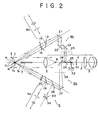
- Figs. l'through 6 illustrate a non-contact type tonometer according to a first embodiment of the present invention, wherein:
- Figs. 1 through 6 illustrate a first embodiment of a non-contact type tonometer according to the present invention.
- reference numeral 1 denotes an observation optical system
- p denotes an optical axis thereof.
- Reference numeral 2 denotes a cornea of an eye to be tested.
- the observation optical system 1 generally comprises a lens 3, an aiming plate 4 as observation means, and an ocular 5, so that an image of the anterior portion of the eye to be tested can be enlarged for observation by the ocular 5.
- Disposed at a focal position of the lens 3 is a fixation light source 6.
- a person to be tested sights this fixation light source 6 at an indefinite distance through the lens 3 while being tested.
- the observation optical system 1 is provided at a co-axis of its optical axisl a fluid ejection nozzle 7.
- the fluid ejection nozzle 7 has such a function as to eject an air pulse as a fluid for transfiguring the cornea from a front end 7a of the nozzle 7 toward the cornea 2 to be tested.
- the cornea 2 is flatened under pressure in an applanation state as shown in Fig. 3 by the air pulse.
- the air pulse is ejected when a corneal axial line m connecting a corneal curvature center 0 1 to a corneal vertex 0 2 is in alignment with the optical axis l, and a distance 1 1 from the corneal vertex 0 2 to the nozzle front end 7a is set in a predetermined distance.
- the non-contact type tonometer has an alignment adjustment apparatus for adjusting a position from the nozzle front end 7a to the corneal vertex 0 2 .
- the alignment apparatus comprises a first alignment optical system 8, and a second alignment optical system 9.
- the pair of alignment optical systems 8 and 9 intersect at one point at the respective optical axes thereof and located on the optical axis Y of the observation optical system.
- a first index projection system 8a of the first alignment optical system 8 comprises an index light source 10, a lens 11, a diaphragm 12, a half mirror 13, a variable diaphragm 14, and a lens 15.
- a second index projection system 9a of the second alignment optical system 9 generally comprises an index light source 16, a lens 17, a diaphragm 18, a half mirror 19, and a lens 20.
- the index spot light from the index light source 10 is formed with an image within a plane including the diaphragm by tne lens 11, guided to the lens 15 as if it were produced from the diaphragm 12, and converted to parallel bundle of rays for projecting toward the cornea 2 by tne lens 15.
- the spot light from the index light source 16 is formed with an image within a plane including the diaphragm 18 by the lens 17, guided to the lens 20 as if it were produced from the diaphragm 18, and converted to parallel bundle of rays for projecting toward the cornea by the lens 20.
- the cornea 2 is formed with virtual images il and i2 of an index spot light by the specular reflection thereof. These virtual images il and i2 are formed in symmetric positions with an optical axis l serving as a symmetric line when a corneal axial line m and the optical axis are brought to be in alignment with each other.
- the first alignment optical system 8 has, as shown in Fig. 2, a first index detection system 8b for guiding a reflection light for forming the virtual image i2 to the aiming plate 4 through a half mirror 13, total reflection mirrors 21, 22 and 23, and half mirrors 24 and 25.
- the second alignment optical system 9 has a second index detection system 9b for guiding a reflection light for forming the virtual image il to the aiming plate 4 through a half mirror 19, 26, a total reflection mirror 27, and half mirrors 28, 24, and 25.
- the aiming plate 4 is formed with a pair of index images Sl corresponding to the index spot light.
- the pair of index images S1 are, as shown in Fig. 4, brought to be in a superposed relation at an intersecting point of a cross line of the aiming plate 4, when the optical axis l and the corneal axial line m are brought to be in alignment with each other, and a distance l1 from a nozzle front end 7a to a corneal vertex 02 is set to a predetermined distance d.
- the pair of index images S1 are visually confirmed in a separated state, and at the same time, the pair of index images Sl are out of pint or blurred. Accordingly, an alignment control can be made by confirming the superposed relation of the pair of index images Sl, and the alignment at the intersecting point of the cross line.
- liquid crystal shutters 29 and 30 as douser plates in the middle of an optical system path for guiding the reflection light for forming the virtual images il and i2 based on the corneal specular reflection to the aiming plate 4.
- the liquid crystal shutters 29 and 30 are electrically controlled, so that when one of the liquid crystal shutters 29 and 30 is in its doused state, the other is in a non-doused state.
- tne blinking of the index image Sl can be visually confirmed. Accordingly, whether the pair of index images S1 are in superposed relation can be confirmed by confirming the blinking of the pair of index images Sl.
- the half mirror 25 has the function that a part of the reflection light for forming the virtual images i1 and i2 based on the corneal specular reflection is guided to a detector 32 through a diaphragm 31.
- the detector 32 has the function that the detection light quantity becomes maximum when the corneal axial line ml and the optical axis ) are in alignment and the distance d from the corneal vertex 02 to the nozzle front end 7a is set to the predetermined distance, and a drive signal is outputted toward an air pulse generator (not shown). Actuation of the air pulse generator causes the air pulse to be ejected from the fluid ejection nozzle 7. In Fig. 3, an arrow X shows the ejecting direction of the air pulse.
- the first alignment optical system 8 serves as a detection light projection optical system for projecting a corneal transfiguration detection light when the cornea is transfigured.
- a part of tne second alignment optical system constitutes a part of the light receiving optical system for receiving the reflection light of the corneal transfiguration detection light.
- the index spot light from the index light source 10 is guided to the half mirror 13 as a corneal transfiguration detection light, diaphragmed by a variable diaphragm 14 and guided to a lens 15, and parallel bundle of rays are projected toward the corneal 2 and reflected by the cornea 2.
- the reflection light is guided to a diaphragm 33 through lens 20, half mirror 19, and half mirror 26, and formed an image at the diaphragm 33, and is detected by a detector 34. Due to the foregoing, the applanation state of the cornea 2 is electrically detected.
- Figs. 7 and 8 illustrate a non-contact type tonometer according to second embodiment of the present invention, in which an objective lens 35 is provided by aligning the optical axis I of the observation optical system 1 and the optical axis thereof, and the objective lens 35 is used both for the lens 15 of the first alignment optical system 8 and the lens 20 of the second alignment optical system 9 in the aforementioned first embodiment.
- the diaphragm 12 is disposed at a position of a focus f of the objective lens 35, so that a pair of spot lights are converted to parallel bundle of rays by the objective lens 35 and projected to the cornea 2.
- the reflection light for forming the virtual image i2 based on the corneal specular reflection is guided to the aiming plate 4 through objective lens 35, variable diaphragm 41, half mirror 42, total reflection mirrors 43 and 44, half mirror 40, and half mirror 25, and formed an image on the aiming plate 4. And, a part of the reflection light is guided to the detector 32 by the half mirror 25, as shown in Fig. 7.
- the reflection light for forming a virtual image il based on the corneal specular reflection is guided to the aiming plate 4 through the objective lens 35, half mirror 37, 38, 39, 40, and 25 and formed an image thereon. At the same time, a part of the reflection light is guided to the detector 32 by the half mirror 25.
- the first alignment optical system 8 serves as a detection light projection optical system for projecting a corneal transfiguration detection light when the cornea is transfigured
- a part of tne second alignment optical system 9 serves as a-light receiving optical system for receiving a part of the corneal transfiguration detection light.
- the index spot light is diaphragmed by the variable diaphragm 41, guided to the objective lens 35, converted to parallel bundle of rays by the objective lens 35, reflected by the cornea 2 in its applanation state, and guided to the detector 34 through the objective lens 35 and the half mirror 37.
- the objective lens 35 can be used for both the index spot light projection optical systems 8 and 9. Accordingly, the first and the second alignment optical systems 8 and 9 can be constituted more compact compared with those of the first embodiment.
- reference numeral 36 denotes a half mirror for guiding a fixation signt index light from the fixation sight light source 6 to the eye to be tested.
- the nozzle tube 7 and the optical axis f of the observation optical system are in alignment with each other.
- the present invention is not necessarily limited to these embodiments.
- the observation optical system 1 includes an illuminating means 50 for illuminating the anterior portion of the eye under test, an objective lens 51 for forming an image of the anterior portion, and an observing means 52 for observing the image.
- the illuminating means 50 comprises four green light emitting diodes 50a-50d.
- the green light emitting diodes 50a- 50d are arranged around the optical axis l at equal angles.
- An image pick-up tube 53 is used as the observing means 52 in this embodiment, and the image of the anterior portion of the eye to be tested is formed on the sensing surface 53a of the image pick-up tube 53 through the objective lens 51.
- a reticle image is formed on the sensing surface 53a through a reticle image projection optical system as will be described later.
- the fixation mark projection optical system 54 includes a green light emitting diode 55 as a fixation sight light source, a fixation sight mark plate 56, a total reflection mirror 57, and a half mirror 58.
- a diopter compensation optical system 59 is disposed between the total reflection mirror 57 and the half reflection mirror 58.
- the diopter compensation optical system 59 comprises a group of lenses mounted on a turret plate 60, as shown in Fig. 13.
- the turret plate 60 is fixed with diopter compensation lenses 60a-60e in its peripheral direction.
- 61 denotes a rotary shaft of the turret plate 60.
- the lens 60a is for 0 diopter.
- the lens 60b is for -3 diopter, lens 60c for - 10 diopter, lens 60d for +10 diopter and lens 60e for +3 diopter.
- the rotation of the turret plate 60 causes the lenses 60a-60e to be selectively added to the fixation mark projection optical system 54 so that diopter of the eye under test may be compensated.
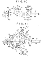
- the first alignment optical system 8 comprises an infrared light emitting diode 62 serving as an index spot light forming means, an index projection optical system 63 adapted to project the infrared light serving as the index spot light in the form of parallel bundle of rays toward the cornea 2, and an index detection system 64 adapted to introduce a virtual image of the index spot light produced by means of the corneal specular reflection of the eye under test 2 to a sensing surface 53a through an index projection optical system (as will be described later) of the other alignment optical system 9.
- the second alignment optical system 9 comprises an infrared light emitting diode 65 serving as an index spot light forming means, an index projection optical system 66 adapted to project the infrared light serving as the index spot light in a form of parallel bundle of rays toward the cornea 2, and an index detection system 67 adapted to guide a virtual image of the index spot light produced by means of the corneal specular reflection of the eye 2 under test to the sensing surface 53a through an index projection optical system 63 of the other alignment optical system 8.
- the index projection optical system 63 generally comprises a band-pass filter 68, a lens 69, a half mirror 70 and an objective lens 71.
- the index projection optical system 66 generally comprises a band-pass filter 72, a lens 73, a half mirror 74, and an objective lens 75.
- the infrared light emitting diode 62 and the infrared light emitting diode 65 emit infrared lights having different wavelengths with respect to each other.
- the wavelength of the light emitted by the infrared light emitting diode 62 is in the vicinity of 760 nm at its central wavelength
- the wavelength of the light emitted by the other infrared light emitting diode 65 is in the vicinity of 830 nm at its central wavelength.
- the band-pass filter 68 has such a function as to selectively transmit the infrared lignt of the wavelength bands as indicated by character C in Fig. 14.
- the other band-pass filter 72 has such a function as to selectively transmit the infrared light in the wavelength band as indicated by cnaracter D in Fig. 14.
- reference character E denotes a transmittance characteristic of a band-pass filter 76.
- the band-pass filter 76 is disposed between the objective lens 51 and the half mirror 58 of the observation optical system 1, and has such a function as to cut the infrared light and permit the reflected green light reflected on the anterior portion of the eye under test to transmit therethrough.
- the band-pass filter 68 and band-pass filter 72 are formed with diaphragms 68a, 72a by means of vacuum evaporation coating film, respectively.
- the infrared light emitted from the infrared light emitting diode 62 and the infrared light emitted from the other infrared light emitting diode 65 are diaphragmed with the flux of light by the diaphragms 68a, 72a and introduced to the lenses 69, 73, respectively.
- the lenses 69 and 73 have such functions as to form intermediate images P 1 , P 2 from the respective infrared light.
- the objective lenses 71, 75 are positioned to be coincident the focal points thereof with the positions where the intermediate images P 1 , P 2 are formed, and have such functions as to convert the infrared lights which were once formed as the intermediate images P 1 , P 2 to parallel bundle of rays. As shown in Fig.
- the cornea 2 is formed with virtual images i l , i 2 of the index spot light by the corneal specular reflection based on the projection of the parallel bundle of rays, when the corneal axial line m and optical axis e are brought to be in alignment with respect to each other, the symmetrical positions are formed, with the corneal axial line m serving as an axis of symmetry.
- the virtual image i 1 is formed by occurrence of projection of the index spot light of the first alignment optical system 8, while the other virtual image i 2 is formed by occurrence of projection of the index spot light of the second alignment optical system 9. As shown in Fig.
- the index projection optical system 63 has such a function as to introduce the reflection light which forms the virtual image i 2 to the index detection system 67 through the half mirror 70. While, the other index projection optical system 66 has such a function as to introduce the reflection light which forms the virtual image i l to the index detection system 64 through the half mirror 74.
- the index detection system 64 comprises a filter 77, and a total reflection mirror 78. While, the index detection system 67 comprises a filter 79 and a total reflection mirror 80.
- a filter 79 has such a function as to cut the infrared light having its central wavelength of 760 nm and permit the infrared light having its central wavelength of 830 nm to transmit therethrough.
- a filter 77 has such a function as to cut the infrared light having its central wavelength of 830 nm and permit the infrared light having its central wavelength of 760 nm to transmit therethrough.
- the reflection light for forming the virtual images i 1 , i 2 are introduced to the sensing surface 53a of the image pick-up tube 53 as observating means by index detection systems 64, 67, and formed as a pair of index images S i thereon.
- a reticle image projection optical system 81 will be described next.
- the reticle image projection optical system 81 comprises an illumination light source 82, a reticle plate 83, a projection lens 84, and a half mirror 85.
- a reticle image 86 is, as shown in Fig. 15, formed on the sensing surface 53a of the image pick-up tube 53 by the reticle image projection system 81.
- 86a denotes a cross line
- 86b denotes a boundary frame adapted to determine the completion of alignment.
- the half mirror 85 has such a function as to introduce a part of the corneal specular reflection lignt to the detector 32.
- the detector 32 is arranged in an optical conjugate position with the image sensing surface 53a of the image pick-up tube 53.
- a filter 87 is provided between the half mirror 85 and the detector 32 in order to cut the illumination light of the illumination light source 82 and 50a-50d and permit the infrared light to transmit therethrough and to reflect thereon. Because of the foregoing arrangement, the detector 32 can receive only the corneal specular reflection light without getting influence of the illumination light emitted from the illumination light source 82.
- the pair of index images S 1 are, as shown in Fig. 16, caused to be in a superposed relation with respect to each other at the intersecting point of the cross line 86a of the reticle plate and simultaneously the images become sharp.
- the pair of index images S 1 are, as shown in Figs. 17 and 18, recognized by sight in separated states, and simultateously the pair of index images S 1 are in such states as to be blurred. Accordingly, the alignment can be controlled in such a manner as to confirm the mutual superposition of the index images S 1 and the alignment of the images with the intersecting point of the cross line 86a through the image pick-up tube 53.
- the first alignment optical system 8 serves as a projection optical system of a corneal transfiguration monitoring system for projecting the corneal transfiguration detecting light onto the cornea at the time when the cornea 2 is transfigured. While, a part of the second alignment optical system 9 constitutes a part of the receiving optical system of the corneal transfiguration monitoring system for receiving the reflection light of the corneal transfiguration detection light.
- the index sp'ot light emitted from the infrared light emitting diode 62 is, as shown in Fig. 11, introduced to the diaphragm 68a as the corneal transfiguration detection light, then introduced to the lens 69 after diaphragmed by the diaphragm 68a, and formed as an intermediate image P 1 by the lens 69.
- the width of the optical flux of the infrared light serving as the corneal transfiguration detection light is identical with that of the optical flux of the infrared light serving as the index spot light in this embodiment.
- the intermediate image P 1 is converted to the parallel bundle of rays by the objective lens 7 and projected to the cornea 2.
- the corneal transfiguration detection light is, as shown in Fig. 11, reflected on tne cornea 2 and introduced to the objective lens 75.
- a half mirror 8d constituting a part of the receiving optical system is disposed between the objective lens 75 and the half mirror 74.
- the half mirror 74 has such a function as to reflect the corneal transfiguration detection light toward the direction where the diaphragm. 89 exists.
- the diaphragm 89 constitutes a part of the receiving optical system.
- the diaphragm 89 is arranged in a conjugate position with respect to the focal position of the objective lens 75.
- the corneal transfiguration detection light is formed as an intermediate image P 3 in the position where the diaphragm 89 is located by the objective lens 75.
- the size of the intermediate image P 3 is identical with that of an opening 89a formed in the diaphragm 89.
- the intermediate image P 3 is formed on a detector 34 through a relay lens 90. Based on the foregoing, the state of flatness under pressure is electrically detectable from the changes of the reflected optical quantity of the cornea 2.
- 91 denotes a dust-proofing glass plate.
- the filter 79 cuts the reflected infrared light which forms the virtual image i l and permits only the reflected infrared light which forms the virtual image i 2 to transmit therethrough
- the other filter 77 cuts the reflected infrared light which forms the virtual image i 2 and permits only the reflected infrared light which forms the virtual image i l to transmit therethrough.
- an index spot light for alignment and a corneal transfiguration detection light are different in wavelengths with each other.
- An index projection optical system 63 includes an index spot light generation means, and corneal transfiguration detection light generation means.
- the index spot light generation means and the corneal transfiguration detection light generation means generally comprise an incandescent lamp 223 as a common illumination light source, a high-pass filter 224, and a wavelength selection filter 225.
- the high-pass filter 224 has the function to transmit an illumination light having a wavelength of more than 600 nm among illumination light ejected from the incandescent lamp 223.
- the wavelength selection filter 225 has the function, as shown in Fig.
- Fig. 21 illustrates a characteristic of this wavelength selection filter 225, wherein reference character A' denotes a filter characteristic at a central portion 225a thereof, while reference character B' denotes a filter characteristic at a peripheral portion 225b thereof.
- reference character C' denotes a filter characteristic of a high-pass filter 224.
- An illumination light ejected from the incandescent lamp 223 passes through the high-pass filter 224 and the wavelength selection filter 225 and becomes a corneal transfiguration detection light L2 (light flux shown by hatching) and an index spot light L3.
- an illumination light having a wavelength range of from 600 nm to 700 nm is used as the corneal transfiguration detection light L2 as shown by reference character E' in Fig. 23, and an illumination light having a wavelength range of more than 700 nm as an index spot light L3 as shown by reference character D' in Fig. 23.
- reference character F' denotes a transmission wavelength cnaracteristic of a band pass filter 76 same as in the'above-mentioned third embodiment.
- An index projection optical system 66 comprises an incandescent lamp 228 as an illumination light source, a high-pass filter 229, a visible light reflection mirror 88, a nalf mirror 74, and an objective lens 75 for using both alignment/applanation detection.
- the high-pass filter 229 has the function to cut an illumination light having a wavelength range of less than 600 nm among illumination light ejected from the incandescent lamp 22d, and transmit the illumination light having a wavelengtn range of more than 600 nm.
- the visible light reflection mirror 88 has the function to reflect the illumination light having a wavelength range of less than 700 nm and to transmit the light having more than 700 nm in wavelength.
- the illumination light ejected from the incandescent lamp 228 becomes an index spot lignt L3 having a wavelength range of more than 700 nm at a time when it passes through the high-pass filter 229 ana tne visiole light reflection mirror 88.
- a pair of alignment optical systems in symmetric positions with an optical axis of an observation optical system serving as a symmetric line for projecting a pair of index spot lights toward a cornea after converting it to parallel bundle of rays and forming a virtual image of a pair of index spot lights due to corneal specular reflection in symmetric positions relative to each other with the optical axis of the observation optical system serving as a symmetric line at a time when a corneal axial line and an optical axis of the observation optical system are brought to be in alignment with each other.
- the pair of alignment optical systems are constituted as such that a reflection light of an index spot light ejected from one of the alignment optical systems and adapted to form a virtual image based on a corneal specular reflection is formed an index image on an aiming plate through the other alignment optical system. Accordingly, when the optical axis of the observation optical system and the corneal axial line connecting the corneal vertex to the corneal curvature center are not in alignment relative to each other, and the distance from the corneal vertex to the ejection nozzle front end is not set to a predetermined distance, a pair of index images corresponding to virtual images based on the corneal specular reflection are visually confirmed in separated state and in blurred state.
- the invention has such an advantage as that the work distance does not depend on the radius of curvature of the cornea under test.
Landscapes
- Life Sciences & Earth Sciences (AREA)
- Health & Medical Sciences (AREA)
- Medical Informatics (AREA)
- Biophysics (AREA)
- Ophthalmology & Optometry (AREA)
- Engineering & Computer Science (AREA)
- Biomedical Technology (AREA)
- Heart & Thoracic Surgery (AREA)
- Physics & Mathematics (AREA)
- Molecular Biology (AREA)
- Surgery (AREA)
- Animal Behavior & Ethology (AREA)
- General Health & Medical Sciences (AREA)
- Public Health (AREA)
- Veterinary Medicine (AREA)
- Eye Examination Apparatus (AREA)
Applications Claiming Priority (6)
| Application Number | Priority Date | Filing Date | Title |
|---|---|---|---|
| JP59248762A JPS61128937A (ja) | 1984-11-27 | 1984-11-27 | 非接触式眼圧計のアライメント調整装置 |
| JP248762/84 | 1984-11-27 | ||
| JP59994/85 | 1985-03-25 | ||
| JP60059994A JPS61220626A (ja) | 1985-03-25 | 1985-03-25 | 非接触式眼圧計 |
| JP68189/85 | 1985-03-30 | ||
| JP60068189A JPS61226016A (ja) | 1985-03-30 | 1985-03-30 | 非接触式眼圧計 |
Publications (3)
| Publication Number | Publication Date |
|---|---|
| EP0183621A2 true EP0183621A2 (fr) | 1986-06-04 |
| EP0183621A3 EP0183621A3 (en) | 1988-04-27 |
| EP0183621B1 EP0183621B1 (fr) | 1992-09-02 |
Family
ID=27297060
Family Applications (1)
| Application Number | Title | Priority Date | Filing Date |
|---|---|---|---|
| EP85402309A Expired EP0183621B1 (fr) | 1984-11-27 | 1985-11-26 | Tonomètre sans contact |
Country Status (3)
| Country | Link |
|---|---|
| US (1) | US4665923A (fr) |
| EP (1) | EP0183621B1 (fr) |
| DE (1) | DE3586581T2 (fr) |
Cited By (8)
| Publication number | Priority date | Publication date | Assignee | Title |
|---|---|---|---|---|
| US4817620A (en) * | 1986-09-06 | 1989-04-04 | Tokyo Kogaku Kikai Kabushiki Kaisha | Noncontact type tonometer |
| US4834105A (en) * | 1986-11-07 | 1989-05-30 | Keeler Limited | Calibration method and apparatus for tonometers |
| EP0354002A1 (fr) * | 1988-08-05 | 1990-02-07 | Leica Inc. | Système d'alignement d'un instrument ophtalmologique |
| US4944303A (en) * | 1986-12-27 | 1990-07-31 | Topcon Corporation | Noncontact type tonometer |
| US4951670A (en) * | 1987-03-06 | 1990-08-28 | Canon Kabushiki Kaisha | Non-contact eye pressure meter |
| US5076274A (en) * | 1987-02-18 | 1991-12-31 | Canon Kabushiki Kaisha | Non-contact tonometer |
| GB2378771A (en) * | 2001-08-14 | 2003-02-19 | Keeler Ltd | Tonometer with proximity indicator |
| CN109926377A (zh) * | 2017-12-15 | 2019-06-25 | 杉野机械股份有限公司 | 喷嘴的检查方法及其装置 |
Families Citing this family (20)
| Publication number | Priority date | Publication date | Assignee | Title |
|---|---|---|---|---|
| US4872460A (en) * | 1986-08-21 | 1989-10-10 | Tokyo Kogaku Kikai Kabushiki Kaisha | Noncontact type tonometer |
| US4991584A (en) * | 1986-10-25 | 1991-02-12 | Canon Kabushiki Kaisha | Ophthalmic examining apparatus and method capable of examining glaucoma |
| JPH01195839A (ja) * | 1988-02-01 | 1989-08-07 | Topcon Corp | 眼科器械 |
| JP2642397B2 (ja) * | 1988-04-21 | 1997-08-20 | 株式会社トプコン | 非接触式眼圧計 |
| JP2642402B2 (ja) * | 1988-05-11 | 1997-08-20 | 株式会社トプコン | 非接触式眼圧計 |
| GB2223107B (en) * | 1988-09-22 | 1992-08-19 | Canon Kk | Non-contact tonometer |
| DE3931630A1 (de) * | 1989-09-22 | 1991-05-08 | Datron Electronic Gmbh | Verfahren und vorrichtung zur bestimmung des augeninnendrucks o. dgl. |
| JP2886936B2 (ja) * | 1990-04-06 | 1999-04-26 | キヤノン株式会社 | 眼の位置合わせ装置 |
| JPH05253190A (ja) * | 1991-10-10 | 1993-10-05 | Massie Res Lab Inc | 非接触式トノメーター |
| US5810005A (en) | 1993-08-04 | 1998-09-22 | Dublin, Jr.; Wilbur L. | Apparatus and method for monitoring intraocular and blood pressure by non-contact contour measurement |
| US5954645A (en) * | 1998-04-03 | 1999-09-21 | Leica Microsystems Inc. | Applanation detection system for a non-contact tonometer |
| US6197197B1 (en) * | 1998-04-23 | 2001-03-06 | Dialysis Systems, Inc. | Method for fluid delivery in a dialysis clinic |
| JP3346468B2 (ja) * | 1998-07-29 | 2002-11-18 | 株式会社トプコン | 非接触式眼圧計 |
| DE10123098A1 (de) * | 2001-05-07 | 2002-11-28 | Epsa Elektronik Und Praez Sbau | Tonometeranordnung |
| US6669340B2 (en) | 2001-11-06 | 2003-12-30 | Reichert, Inc. | Alignment system for an ophthalmic instrument |
| US6945650B2 (en) | 2001-11-06 | 2005-09-20 | Reichert, Inc. | Alignment system for hand-held ophthalmic device |
| JP3762285B2 (ja) * | 2001-11-19 | 2006-04-05 | キヤノン株式会社 | 非接触眼圧計 |
| US10554961B2 (en) * | 2016-11-08 | 2020-02-04 | Kevin Vora | Three-dimensional volumetric display using photoluminescent materials |
| US11219367B2 (en) | 2020-01-30 | 2022-01-11 | Reichert, Inc. | Positioning system for ophthalmic instrument |
| CN113080814B (zh) * | 2021-04-12 | 2022-01-28 | 中南大学 | 一种透射共轴式的光声内窥探头及其成像方法 |
Family Cites Families (5)
| Publication number | Priority date | Publication date | Assignee | Title |
|---|---|---|---|---|
| US3585849A (en) * | 1968-10-09 | 1971-06-22 | American Optical Corp | Method and apparatus for measuring intraocular pressure |
| US3538754A (en) * | 1969-01-15 | 1970-11-10 | American Optical Corp | Method for measuring intraocular pressure |
| US3882718A (en) * | 1971-05-05 | 1975-05-13 | American Optical Corp | Noncontacting pressure measuring apparatus |
| US3756073A (en) * | 1971-11-26 | 1973-09-04 | American Optical Corp | Non-contact tonometer |
| US3832890A (en) * | 1971-12-29 | 1974-09-03 | American Optical Corp | Non-contact tonometer corneal monitoring system |
-
1985
- 1985-11-26 US US06/801,960 patent/US4665923A/en not_active Expired - Fee Related
- 1985-11-26 EP EP85402309A patent/EP0183621B1/fr not_active Expired
- 1985-11-26 DE DE8585402309T patent/DE3586581T2/de not_active Expired - Fee Related
Cited By (10)
| Publication number | Priority date | Publication date | Assignee | Title |
|---|---|---|---|---|
| US4817620A (en) * | 1986-09-06 | 1989-04-04 | Tokyo Kogaku Kikai Kabushiki Kaisha | Noncontact type tonometer |
| US4834105A (en) * | 1986-11-07 | 1989-05-30 | Keeler Limited | Calibration method and apparatus for tonometers |
| US4944303A (en) * | 1986-12-27 | 1990-07-31 | Topcon Corporation | Noncontact type tonometer |
| US5076274A (en) * | 1987-02-18 | 1991-12-31 | Canon Kabushiki Kaisha | Non-contact tonometer |
| US4951670A (en) * | 1987-03-06 | 1990-08-28 | Canon Kabushiki Kaisha | Non-contact eye pressure meter |
| EP0354002A1 (fr) * | 1988-08-05 | 1990-02-07 | Leica Inc. | Système d'alignement d'un instrument ophtalmologique |
| GB2378771A (en) * | 2001-08-14 | 2003-02-19 | Keeler Ltd | Tonometer with proximity indicator |
| GB2378771B (en) * | 2001-08-14 | 2003-12-17 | Keeler Ltd | Hand held tononeter including optical proximity indicator |
| CN109926377A (zh) * | 2017-12-15 | 2019-06-25 | 杉野机械股份有限公司 | 喷嘴的检查方法及其装置 |
| CN109926377B (zh) * | 2017-12-15 | 2021-08-31 | 杉野机械股份有限公司 | 喷嘴的检查方法及其装置 |
Also Published As
| Publication number | Publication date |
|---|---|
| EP0183621A3 (en) | 1988-04-27 |
| DE3586581D1 (de) | 1992-10-08 |
| US4665923A (en) | 1987-05-19 |
| DE3586581T2 (de) | 1993-04-15 |
| EP0183621B1 (fr) | 1992-09-02 |
Similar Documents
| Publication | Publication Date | Title |
|---|---|---|
| EP0183621B1 (fr) | Tonomètre sans contact | |
| US5463430A (en) | Examination apparatus for examining an object having a spheroidal reflective surface | |
| US4944303A (en) | Noncontact type tonometer | |
| EP1138257B1 (fr) | Appareil ophthalmique | |
| EP1088511B1 (fr) | Appareil ophthalmique | |
| JPH0366355A (ja) | トポグラフィ測定方法とその装置 | |
| US4705045A (en) | Non-contact type tonometer | |
| US5300965A (en) | Corneal shape measuring apparatus | |
| JP3108261B2 (ja) | 眼科器械 | |
| JPS6365333B2 (fr) | ||
| US5101826A (en) | Noncontact type tonometer | |
| US4398812A (en) | Apparatus and method for measuring the anterior chamber diameter of the eye | |
| US5013146A (en) | Opthalmological measurement apparatus | |
| JPH0554337B2 (fr) | ||
| EP0189350B1 (fr) | Appareil de mesure de la réfraction des yeux | |
| JPH0554338B2 (fr) | ||
| US5000181A (en) | Noncontact type tonometer | |
| JP3056800B2 (ja) | 眼科装置 | |
| JPH0554325B2 (fr) | ||
| JP3046600B2 (ja) | 眼科装置 | |
| JP2568586B2 (ja) | エアパフ型眼圧計 | |
| JPH0554326B2 (fr) | ||
| JP3154533B2 (ja) | 眼科装置 | |
| JPH0439332B2 (fr) | ||
| JP3156859B2 (ja) | 非接触式眼圧計 |
Legal Events
| Date | Code | Title | Description |
|---|---|---|---|
| PUAI | Public reference made under article 153(3) epc to a published international application that has entered the european phase |
Free format text: ORIGINAL CODE: 0009012 |
|
| 17P | Request for examination filed |
Effective date: 19851129 |
|
| AK | Designated contracting states |
Kind code of ref document: A2 Designated state(s): CH DE FR GB IT LI NL |
|
| PUAL | Search report despatched |
Free format text: ORIGINAL CODE: 0009013 |
|
| AK | Designated contracting states |
Kind code of ref document: A3 Designated state(s): CH DE FR GB IT LI NL |
|
| RAP1 | Party data changed (applicant data changed or rights of an application transferred) |
Owner name: KABUSHIKI KAISHA TOPCON |
|
| 17Q | First examination report despatched |
Effective date: 19910227 |
|
| GRAA | (expected) grant |
Free format text: ORIGINAL CODE: 0009210 |
|
| AK | Designated contracting states |
Kind code of ref document: B1 Designated state(s): CH DE FR GB IT LI NL |
|
| ITF | It: translation for a ep patent filed | ||
| REF | Corresponds to: |
Ref document number: 3586581 Country of ref document: DE Date of ref document: 19921008 |
|
| PGFP | Annual fee paid to national office [announced via postgrant information from national office to epo] |
Ref country code: FR Payment date: 19921126 Year of fee payment: 8 |
|
| ET | Fr: translation filed | ||
| PGFP | Annual fee paid to national office [announced via postgrant information from national office to epo] |
Ref country code: NL Payment date: 19921130 Year of fee payment: 8 |
|
| PLBE | No opposition filed within time limit |
Free format text: ORIGINAL CODE: 0009261 |
|
| STAA | Information on the status of an ep patent application or granted ep patent |
Free format text: STATUS: NO OPPOSITION FILED WITHIN TIME LIMIT |
|
| 26N | No opposition filed | ||
| PGFP | Annual fee paid to national office [announced via postgrant information from national office to epo] |
Ref country code: CH Payment date: 19931110 Year of fee payment: 9 |
|
| PG25 | Lapsed in a contracting state [announced via postgrant information from national office to epo] |
Ref country code: NL Effective date: 19940601 |
|
| NLV4 | Nl: lapsed or anulled due to non-payment of the annual fee | ||
| PG25 | Lapsed in a contracting state [announced via postgrant information from national office to epo] |
Ref country code: FR Effective date: 19940729 |
|
| REG | Reference to a national code |
Ref country code: FR Ref legal event code: ST |
|
| PG25 | Lapsed in a contracting state [announced via postgrant information from national office to epo] |
Ref country code: LI Effective date: 19941130 Ref country code: CH Effective date: 19941130 |
|
| REG | Reference to a national code |
Ref country code: CH Ref legal event code: PL |
|
| PGFP | Annual fee paid to national office [announced via postgrant information from national office to epo] |
Ref country code: DE Payment date: 19971222 Year of fee payment: 13 |
|
| PG25 | Lapsed in a contracting state [announced via postgrant information from national office to epo] |
Ref country code: DE Free format text: LAPSE BECAUSE OF NON-PAYMENT OF DUE FEES Effective date: 19990901 |
|
| PGFP | Annual fee paid to national office [announced via postgrant information from national office to epo] |
Ref country code: GB Payment date: 20011119 Year of fee payment: 17 |
|
| REG | Reference to a national code |
Ref country code: GB Ref legal event code: IF02 |
|
| PG25 | Lapsed in a contracting state [announced via postgrant information from national office to epo] |
Ref country code: GB Free format text: LAPSE BECAUSE OF NON-PAYMENT OF DUE FEES Effective date: 20021126 |
|
| GBPC | Gb: european patent ceased through non-payment of renewal fee |